resideo TAZ-4H Add A Zone Panel Instruction
APPLICATION
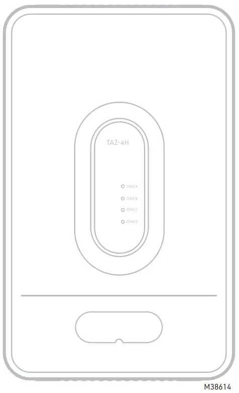
The TAZ-4H is a zone panel used to add zones to the HZ432.
See Fig. 1. The HZ432 provides up to four zones. Each TAZ4H can add up to four additional zones for a total of 32 zones.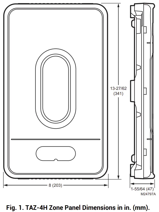
INSTALLATION
When Installing this Product
- Read these instructions carefully. Failure to follow them could damage the product or cause a hazardous condition.
- Check the rating given in the instructions and on the product to make sure the product is suitable for your application.
- Installer must be a trained, experienced service technician.
- After installation is complete, check out product operation as provided in these instructions.
- Follow local codes for installation and application.
 CAUTION
Voltage Hazard. Can cause electrical shock or equipment damage. Disconnect power before beginning installation.
Location
Select a location for the TAZ-4H as close as possible to the HZ432 panel.
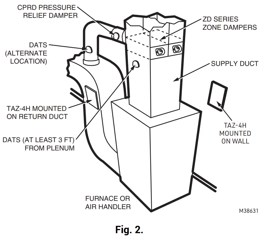
Mounting
The TAZ-4H can mount on a wall, stud, or return duct
Wiring
CAUTION
Electrical Interference Hazard. Running cable near line voltage can interfere with panel operation.
Run cable connecting AZ terminals at least 12 in. from line voltage wiring.
IMPORTANT Be sure AZ1 and AZ2 wires do not cross and are a minimum of 12 in. from any line voltage wiring. If not possible, use shielded cable for AZ1 and AZ2 wires.
NOTE: Only two wires are required to connect the TAZ-4H panels to the main HZ432 panel. If more than oneTAZ-4H is used, each TAZ-4H can be wired in a daisy chain or parallel to each other, connecting the AZ1 and AZ2 terminals between panels. Each AZ1 and AZ2 terminal can fit two wires to simplify daisy chain wiring.
SPECIFICATIONS
Input Ratings:
Voltage: 18-30 VAC 50/60 Hz transformer of 40 VA or more.
Current Draw:
TAZ-4H Zone Panel: 8.5 VA max
Wiring:
18- or 20-gauge solid (not stranded) wire.
Humidity Ratings:
5% to 90% RH non-condensing.
Temperature Ratings:
Shipping: -20° to 150 °F (-29° to 66 °C)
Operating: -40° to 165 °F (-40° to 74 °C)
Dimensions:
See Fig. 1.
Emissions:
Complies with FCC Class B, part 15 requirements.
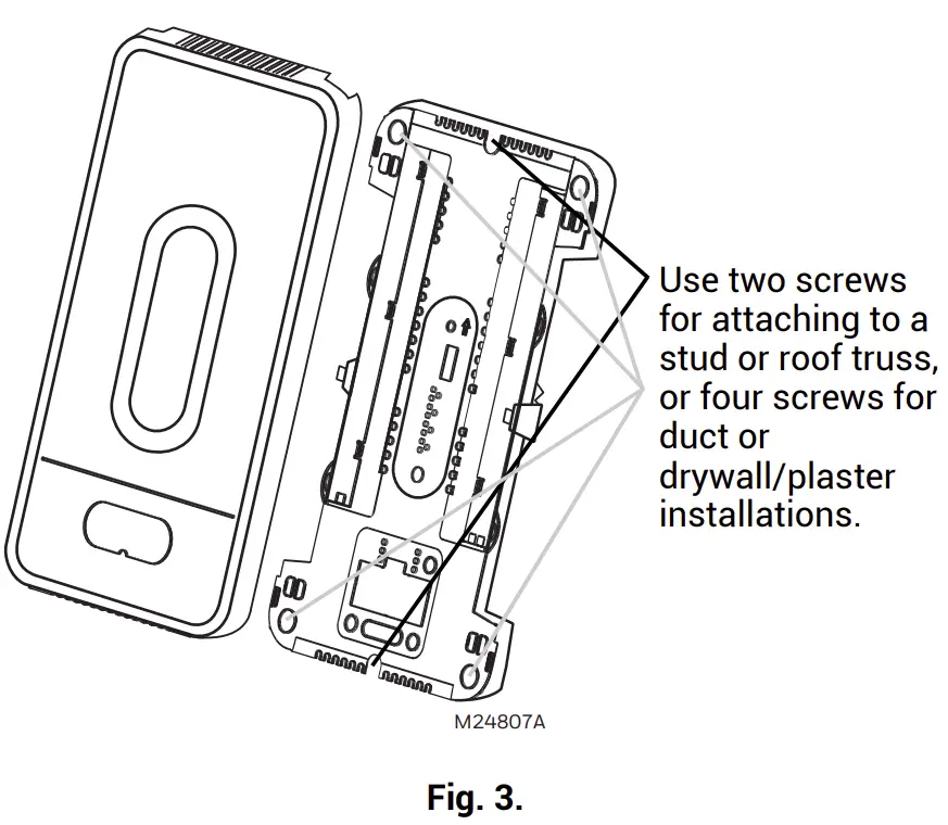
MOUNTING
- Mount the TAZ-4H Add-A-Zone panel near the HVAC equipment; locate it on a wall, stud, roof truss, or cold air return.
NOTE: The TAZ-4H Add-A-Zone panel can be mounted in any orientation; level it for appearance only. It is best to mount the TAZ-4H AddA-Zone panel close to the HZ432 zone panel when possible.
- Separate the zone panel cover from the base, and use the base as a template to drill mounting holes. Attach the base to the wall, stud, roof truss, or duct with appropriate screws (not included).

CAUTION
ELECTRONIC WASTE NOTICE
The product should not be disposed of with other household waste. Check for the nearest authorized collection centers or authorized recyclers. The correct disposal of end of life equipment will help prevent negative consequences for the environment and human health.
Table 1. Recommended Thermostats
System | Thermostat |
| Single stage | TH1110D2009 (Non-Programmable) |
| TH4110U2005 (Programmable) | |
| Multistage conventional | TH6220U2000 (Programmable) |
| TH6220WF2006 (Programmable, Wi-Fi) | |
| Heat pump | TH4210U2002 (2H/1C, Programmable) |
| TH6210U2001 (2H/1C, Programmable) | |
| TH6220U2000 (2H/1C, Programmable) | |
| TH6220WF2006 (2H/1C, Programmable, Wi-Fi) | |
| TH6320WF2003 (3H/2C, Programmable, Wi-Fi) | |
| All the above | TH6320WF2003 (Programmable, Wi-Fi) |
| TH8321WF1001 (Programmable, Wi-Fi) | |
| THX321WFS2001W (Programmable, Wi-Fi) |
Table 2. Recommended Dampers
| Type | Actuation | Round | Rectangular |
| Zone | Spring-open/ power-closed | ARD (8 VA Max) | ZD (8 VA Max) |
| Zone | Power-open/ power-closed | RRD (2.5 VA Max) | — |
Table 3. Maximum Dampers.*
| Ambient Temp. | Maximum Damper VA per Zone |
| 100 °F (38 °C) | 28.8 |
| 160 °F (71 °C) | 16.8 |
* See SDCR in accessories below if you need to exceed the number of dampers allowed to a zone.
Maximum dampers per panel is limited by transformer size. Ensure transformer is large enough to power the panel, thermostats, wireless adapter module, and dampers.
Table 4. Accessories
| Accessory | Description |
| 40 VA transformer | AT140A1042 |
| 75 VA transformer | AT175A1008 |
| SDCR | Secondary Damper Control Relay. Each SDCR allows you to add additional dampers to a zone that is exceeding the maximum from the chart above. |
WIRING
CAUTION
Voltage Hazard.
Can cause electrical shock or equipment damage. Disconnect power before beginning installation. Wire entire panel before applying transformer power
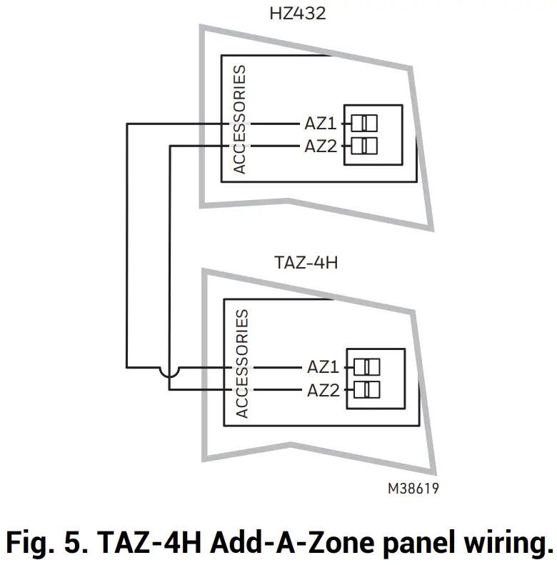
Connect the AZ1 and AZ2 terminals on both panels using standard 18 gauge thermostat wire:
- Connect AZ1 on the HZ432 to AZ1 on the TAZ-4H AddA-Zone panel. See Fig. 5.
- Connect AZ2 on the HZ432 to AZ2 on the TAZ-4H AddA-Zone panel. See Fig. 5.
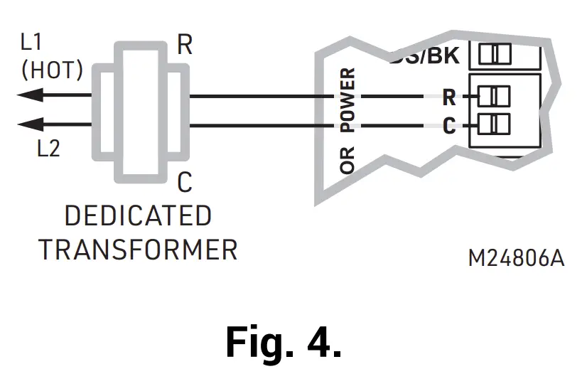
- Connect a 24V, 40 VA transformer to terminals R and C. R is Hot and C is 24 Vac (Common). See Fig. 4.
- Connect thermostat wiring as shown in Fig. 7 through Fig. 11.


- Install dampers using instructions provided with dampers.
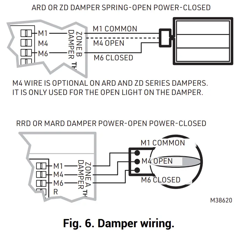
- Connect dampers to zone panel. See Fig. 6.
NOTE: Multiple dampers can be wired in parallel.
CONVENTIONAL
The following diagram is an overall view of wiring thermostats and dampers for a conventional system. The equipment and sensor wiring is done at the HZ432 panel and shown in the literature for that panel.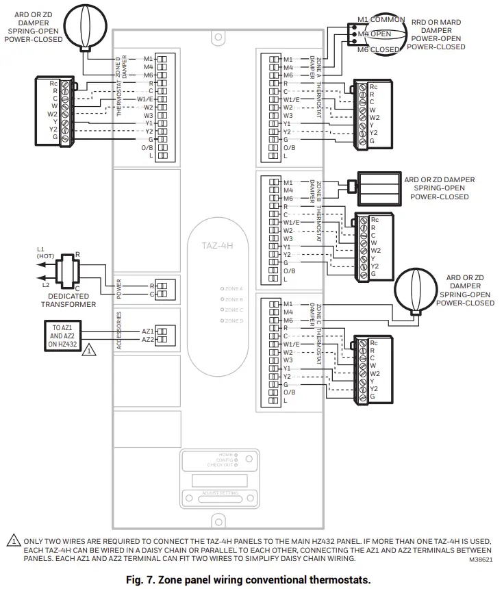
HEAT PUMP
2 Heat/1 Cool Heat Pump with Electric Auxiliary Heat
The following diagram is an overall view of wiring thermostats and dampers for a 2 heat/1 cool heat pump with electric auxiliary heat. The equipment and sensor wiring is done at the HZ432 panel and shown in the literature for that panel.
NOTE: You can use a conventional thermostat for a heat pump system; however, em heat can only be controlled by heat pump thermostats or by pressing the Emergency Heat button on the HZ432 zone panel. The diagram below shows a heat pump thermostat used with a heat pump system.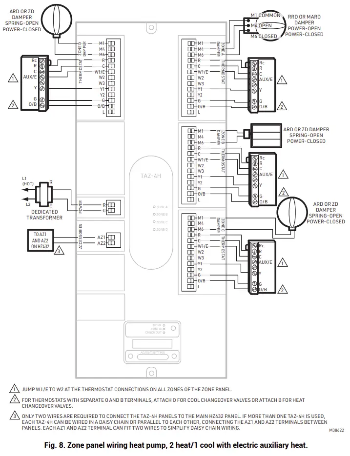
3 Heat/2 Cool Heat Pump with Electric Auxiliary Heat
The following diagram is an overall view of wiring thermostats and dampers for a 3 heat/2 cool heat pump with electric auxiliary heat. The equipment and sensor wiring is done at the HZ432 panel and shown in the literature for that panel.
NOTE: You can use a conventional thermostat for a heat pump system; however, em heat can only be controlled by heat pump thermostats or by pressing the Emergency Heat button on the HZ432 zone panel. The diagram below shows a heat pump thermostat used with a heat pump system.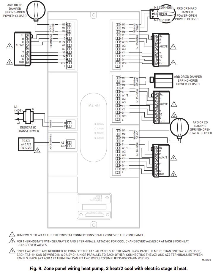
DUAL FUEL
Dual Fuel System with Single-Stage Furnace and Single-Stage Heat Pump
Use the following diagram for wiring a dual fuel system with single-stage furnace and single-stage heat pump. The equipment and sensor wiring is done at the HZ432 panel and shown in the literature for that panel.
NOTE: You can use a conventional thermostat for a heat pump system; however, em heat can only be controlled by heat pump thermostats or by pressing the Emergency Heat button on the HZ432 zone panel. The diagram below shows a heat pump thermostat used with a heat pump system.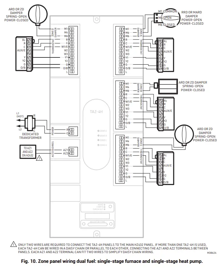
Dual Fuel System with Two-Stage Furnace and Two-Stage Heat Pump
Use the following diagram for wiring a dual fuel system with two-stage furnace and two-stage heat pump. The equipment and sensor wiring is done at the HZ432 panel and shown in the literature for that panel.
NOTE: You can use a conventional thermostat for a heat pump system; however, em heat can only be controlled by heat pump thermostats or by pressing the Emergency Heat button on the HZ432 zone panel. The diagram below shows a heat pump thermostat used with a heat pump system.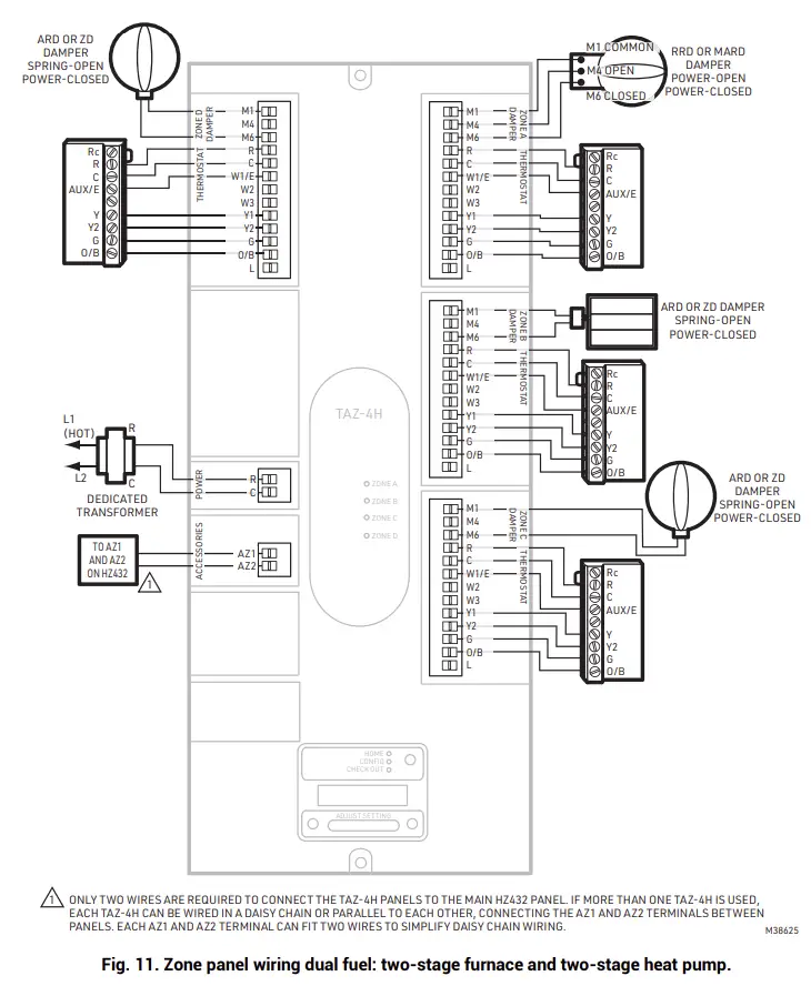
CONFIGURATION
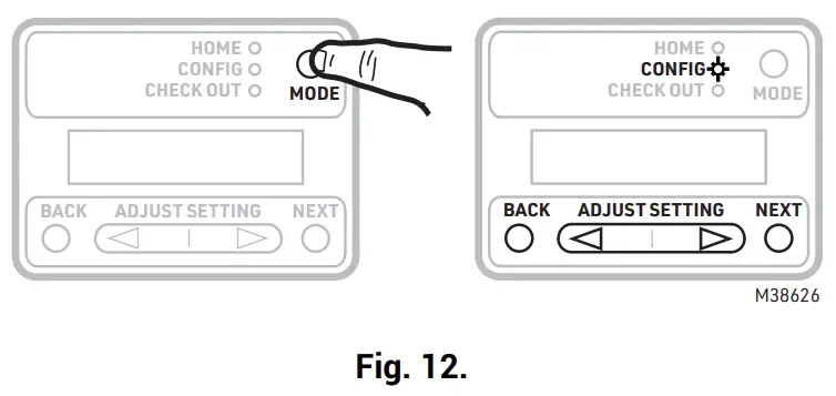
To Enter Configuration
- Press the Mode button once (the Config LED will light up).
- Use the Back and Next buttons to navigate through the configuration settings. Scroll through the selection choices by using the “Adjust Setting” Left and Right arrow buttons. Pressing Next enters the selected option for that menu item and advances to the next menu.
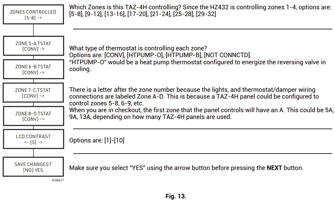
- The flow chart below illustrates TAZ-4H zone panel configuration.


HOME MODE
The display at home mode will either indicate communication is good or at least one zone is failing to communicate to the HZ432 zone panel. The TAZ-4H panel is factory configured for zones 5-8 with conventional thermostats, so it will indicate communication status as soon as it is powered even if it has not been configured.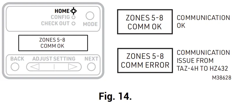
CHECKOUT
To Enter Checkout
- Press the Mode button twice (the Checkout LED will light up).
- The Chart below shows the Checkout options and information shown. Use the Back and Next buttons to navigate through the checkout options. When testing a damper use “Adjust Setting” Left and Right arrow buttons to open or close the damper. Pressing Next advances to the next menu.


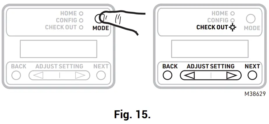
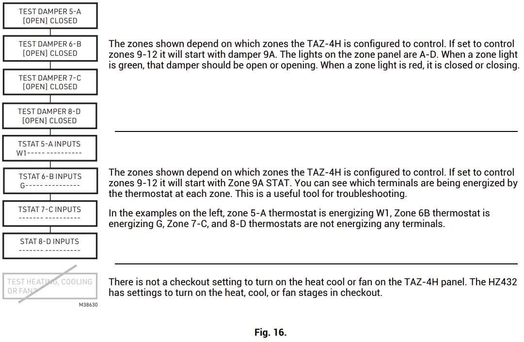
Table 5. LED Operation
| LED | Description |
| Home | Zone Panel is in Home mode. |
| Config | Zone panel is in Configuration mode. |
| Checkout | Zone panel is in Checkout mode. |
| Zone A, B, C, D | Solid green when open or opening. Solid red when closed or closing. Blinking amber when the VA draw of the dampers exceeds the specified VA, or if there is a short circuit on the damper or thermostat wiring, causing that zone’s breaker to trip. |
Troubleshooting
Table 6. Troubleshooting
| Problem | Description |
| TAZ-4H does not communicate to HZ432 |
|
| Damper is in wrong position |
|
| When one of the zones on the TAZ- 4H calls for heat or cool, the HZ432 stays in idle (no heat, cool, or purge light lit). |
|
WARRANTY
Resideo warrants this product to be free from defects in workmanship or materials, under normal use and service, for a period of five (5) years from the date of first purchase by the original purchaser. If at any time during the warranty period the product is determined to be defective due to workmanship or materials, Resideo shall repair or replace it (at Resideo’s option).
If the product is defective,
(i) return it, with a bill of sale or other dated proof of purchase, to the place from which you purchased it; or (ii) call Resideo Customer Care at 1-800-468-1502. Customer Care will make the determination whether the product should be returned to the following address: Resideo Return Goods, 1985 Douglas Dr. N., Golden Valley, MN 55422, or whether a replacement product can be sent to you.
This warranty does not cover removal or reinstallation costs. This warranty shall not apply if it is shown by Resideo that the defect was caused by damage which occurred while the product was in the possession of a consumer.
Resideo’s sole responsibility shall be to repair or replace the product within the terms stated above. RESIDEO SHALL NOT BE LIABLE FOR ANY LOSS OR DAMAGE OF ANY KIND, INCLUDING ANY INCIDENTAL OR CONSEQUENTIAL DAMAGES RESULTING, DIRECTLY OR INDIRECTLY, FROM ANY BREACH OF ANY WARRANTY, EXPRESS OR IMPLIED, OR ANY OTHER FAILURE OF THIS PRODUCT.
Some states do not allow the exclusion or limitation of incidental or consequential damages, so this limitation may not apply to you.
THIS WARRANTY IS THE ONLY EXPRESS WARRANTY RESIDEO MAKES ON THIS PRODUCT. THE DURATION OF ANY IMPLIED WARRANTIES, INCLUDING THE WARRANTIES OF MERCHANTABILITY AND FITNESS FOR A PARTICULAR PURPOSE, IS HEREBY LIMITED TO THE FIVE YEAR DURATION OF THIS WARRANTY. Some states do not allow limitations on how long an implied warranty lasts, so the above limitation may not apply to you.
This warranty gives you specific legal rights, and you may have other rights which vary from state to state. If you have any questions concerning this warranty, please write Resideo Customer Care, 1985 Douglas Dr, Golden Valley, MN 55422 or call 1-800-468-1502
Customer Support
Resideo Technologies, Inc.
1985 Douglas Drive North, Golden Valley, MN 55422
1-800-468-1502
33-00578EFS—01 M.S. 05-21 | Printed in United States