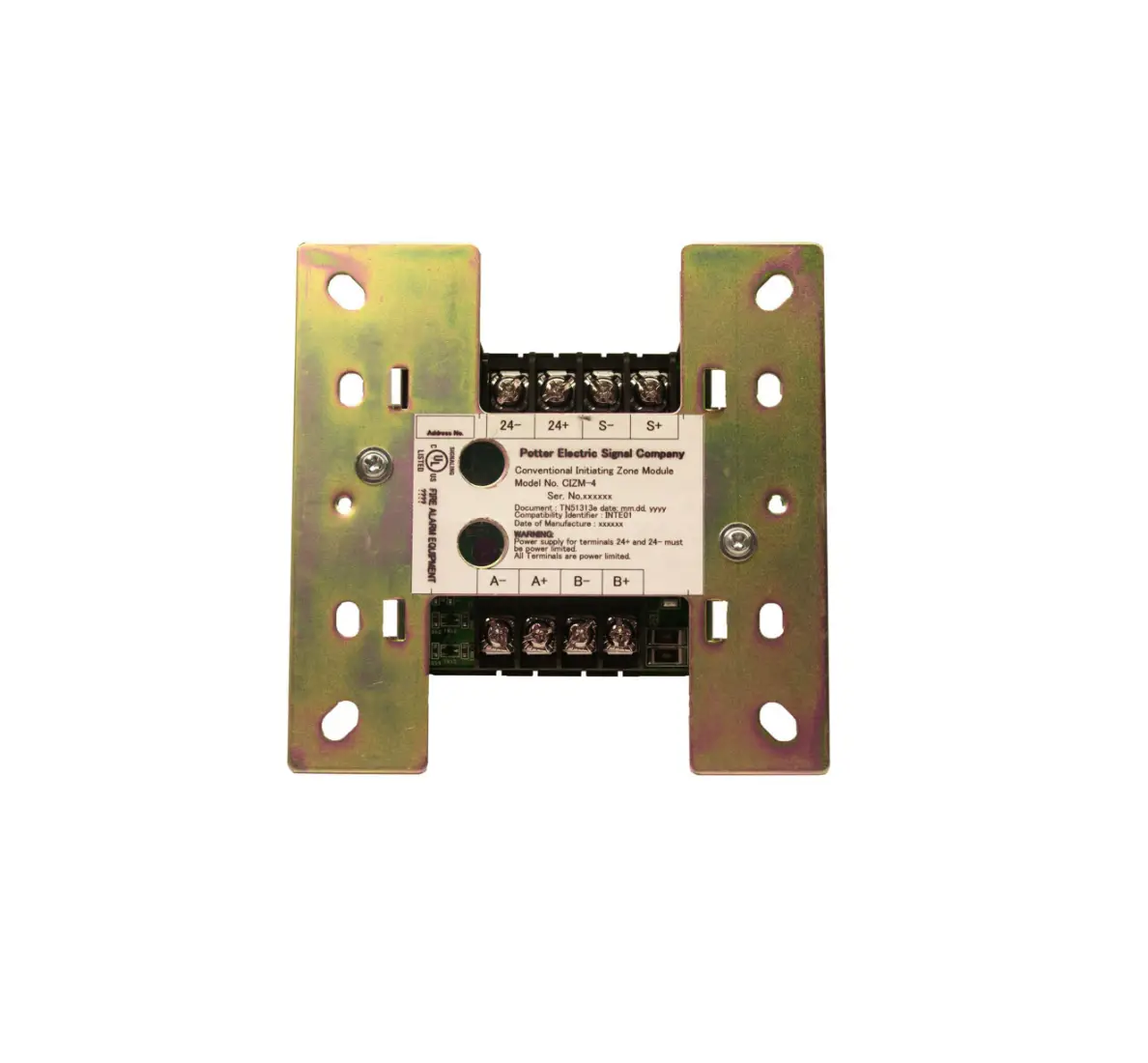
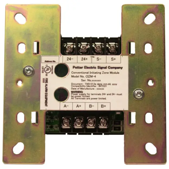
POTTER CIZM-4 Conventional Initiating Zone Module
NOTICE TO THE INSTALLER
This manual provides an overview and the installation instructions for the CIZM-4 module. This module is only compatible with addressable fire systems that utilize the Potter/Nohmi addressable protocol.
All terminals are power limited and should be wired in accordance with the requirements of NFPA 70 (NEC) and NFPA 72 (National Fire Alarm Code). Failure to follow the wiring diagrams in the following pages will cause the system to not operate as intended. For further information, refer to the control panel installation instructions.
The module shall only be installed with listed control panels. Refer to the control panel installation manual for proper system operation.
Description
The module CIZM-4 is used to supervise the status of compatible power consuming initiating devices connected on an Initiating device circuit (IDC). The CIZM-4 detects an alarm condition and reports to the FACP. The module CIZM-4 also supervises the initiating device wiring (A+, A-, B+, and B- wires) and wiring for the power supply connected to terminals 24+ and 24- to detect an open circuit. IDC wiring style is applicable to the NFPA Class B (Style B) & Class A (Style D). When the module CIZM-4 detects an alarm, the module is latched until the system reset. When the CIZM-4 is used in a Class A mode and an open circuit occurs, the module is latched until the system is reset.
The CIZM-4 module has one red LED for local indication of the status of module itself and its wiring. Normal conditions are indicated by flashing LED. The alarm condition is indicated by constant illumination. An open circuit condition is indicated by the lack of the LED operation. The system allows maximum 13 points illuminating constantly therefore if additional devices are in the alarm condition, the LED will flash rather than latch on steady.
Setting the Address
Each addressable module, smoke sensor, heat detector and combination sensor/detector must have the address set prior connecting the device to the SLC loop. The address is set using the hand held device programmer.
Prior to connecting a device to the SLC loop, the following precautions should be taken to prevent potential damage to SLC or device. Verify the following before proceeding. Document discrepancies and notify appropriate personnel.
- Power in the Addressable Module is removed.
- Field wiring on the module is correctly installed.
- Field wiring has no open or short circuits.
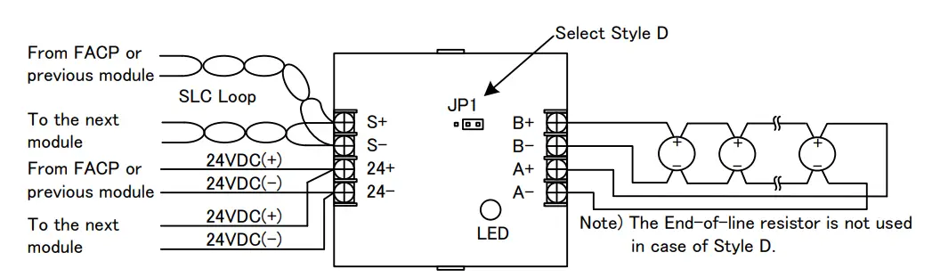
Wiring diagram
Figure 1: Wiring diagram of CIZM-4 in case of Class B (Style B)
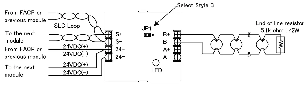
Figure 2: Wiring diagram of CIZM-4 in case of Class A (Style D)
Notes:
- SLC wiring style is applicable to the NFPA Class A (Style 6, 7) & Class B (Style 4).
- IDC wiring style is applicable to the NFPA Class B (Style B) & Class A (Style D).
- Power supply for terminals 24+ and 24- must be power limited.
- SLC loop wiring (S+, S-) and initiating device wiring (A+, A-, B+ and B-) are power limited.
- Wiring for terminals S+, S- are supervised.
- Wiring for terminals 24+, 24- , A+ ,A-, B+, B- are supervised.
- The jumper JP1 shall be set as Style D when the Class A (Style D) is required.
- The jumper JP1 shall be set as Style B when the Class B (Style B) is required.
- Compatible conventional smoke detectors and bases are described in Table 1.
- All wiring is between #14 (2.08 mm2) (max.) and #22 (0.32 mm2) (min.).
- Wire Preparation
Strip all wires approximately 1/4 inch from their edges as follows:
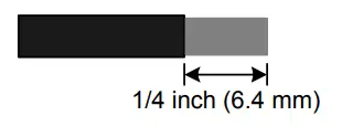
Note:
a) Stripping too much insulation may cause ground fault.
b) Stripping too little may cause a poor connection and subsequently an open circuit.
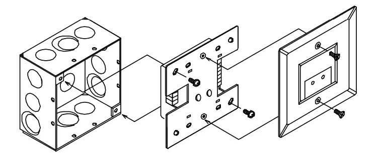
Installation Instructions
Figure 3: Installation into the compatible electrical box
| No. | Item | Specification |
| 1 | Rated voltage range of SLC input power (S+,S-) | 22.0 to 24.0V |
| 2 | Maximum SLC 24 VDC standby current (S+,S-) | 250µA |
| 3 | Maximum SLC 24 VDC alarm current (S+,S-) | 1mA |
| 4 | Operating voltage of external power supply line (24+,24-) | 24V |
| 5 | Output voltage range of IDC (A+,A-,B+,B-) | 15.7 to 22.6V |
| 6 | Maximum module standby current of IDC 24 VDC (24+,24-) | 8.5mA in Style B, 4.9mA in Style D |
| 7 | Maximum detector standby current of IDC 24 VDC (24+,24-) | 2.4mA |
| 8 | Maximum module and detector alarm current of IDC 24 VDC (24+,24-) | 50.0mA |
| 9 | Applicable IDC wiring style | Class A (Style D), Class B (Style B) |
| 10 | Maximum wiring resistance of IDC | 100Ω |
| 11 | Maximum wiring capacitance of IDC | 1µF |
| 12 | End-of-line resistor for IDC in NFPA Style B wiring | 5.1kΩ, 1/2W |
| 13 | Maximum alarm reset voltage | 0 V |
| 14 | Minimum alarm reset time | 1.1 second |
| 15 | Operating temperature range | 32 to 120°F (0 to 49°C) |
| 16 | Operating humidity range | 0 to 93% (non-condensing) |
| 17 | Maximum no. of module per loop | 127 units |
| 18 | Dimensions | 4.17”(106mm) (H) × 4.17”(106mm) (W) × 1.14”(29mm) (D) |
| 19 | Applicable electrical box for installation | 2-1/2”(64mm)deep 2-gang box Standard 4”square box 1-1/2”(38mm)deep box |
| 20 | Compatibility Identifier | INTE01 |
The CIZM-4 will only support a single smoke detector in alarm.
Different brands of smoke detectors shall not be mixed or matched on any CIZM-4 as this condition has not been tested or listed.
Table 1 Compatible conventional smoke detectors and bases
| Manufacturer | Detector | Base | Max. connectable no. | ||
| Model No. | UL approval no. | Model No. | UL approval no. | ||
| SYSTEM SENSOR | 1400 | A | N/A | N/A | 20 units |
| 2400 | A | N/A | N/A | 20 units | |
| 2W-B | A | N/A | N/A | 20 units | |
| 2WT-B | A | N/A | N/A | 20 units | |
| 2WTA-B | A | N/A | N/A | 20 units | |
| DETECTION SYSTEMS | DS250 | A | MB2W/MB2WL | A | 25 units |
| DS250TH | A | MB2W/MB2WL | A | 25 units | |
| DS250HD | A | MB2W/MB2WL | A | 25 units | |
| NOHMI | FDS01U | I51FE1 | FZB01U | FE51A | 25 units |
| FDS01U | I51FE1 | FZB01U-4SX | N/A | No limit(*) | |
| FDK01U | P55FE1 | FZB01U | FE51A | 25 units | |
| FDK01U | P55FE1 | FZB01U-4SX | N/A | No limit(*) | |
| FDKL01U | P56FE1 | FZB01U | FE51A | 25 units | |
| FDKL01U | P56FE1 | FZB01U-4SX | N/A | No limit(*) | |
| FDKU009-D-TX | P55FE1 | FZB01U | FE51A | 25 units | |
| FDKU009-D-TX | P55FE1 | FZB01U-4SX | N/A | No limit(*) | |
| FDHU001-D-X | P56FE1 | FZB01U | FE51A | 25 units | |
| FDHU001-D-X | P56FE1 | FZB01U-4SX | N/A | No limit(*) | |
| FDLU008-D-X | P56FE1 | FZB01U | FE51A | 25 units | |
| FDLU008-D-X | P56FE1 | FZB01U-4SX | N/A | No limit(*) | |
| HOCHIKI | SLR-24 | HD-3 | NS6-220 | HB-3 | 25 units |
| POTTER | PS-24 | HD-3(HOCHIKI) | SB-93 | HB-3 (HOCHIKI) | 25 units |
*Note: there is no limitation for the connection of detector head when the detector base FZB01U-4SX is used, as power supply wiring is separated from IDC wiring
These instructions do not purport to cover all the details or variations in the equipment described, nor provide for every possible contingency to be met in connection with installation, operation and maintenance.
Specifications subject to change without prior notification.
For Technical Assistance contact Potter Electric Signal Company at 800-325-3936.
Actual performance is based on proper application of the product by a qualified professional.
Should further information be desired or should particular problems arise, which are not covered sufficiently for the purchaser’s purpose, the matter should be referred to Nohmi or a distributor in your region.
Customer Support
Potter Electric Signal Company, LLC
1609 Park 370 Place, Hazelwood, MO 63042 USA
Telephone: (866)956-1211
URL: http://www.pottersignal.com