POTTER MCM Miniature Contact Module Instruction Manual
NOTICE TO THE INSTALLER
This manual provides an overview and the installation instructions for the MCM module. This module is only compatible with addressable fire systems that utilize the Potter/Nohmi addressable protocol.
All terminals are power limited and should be wired in accordance with the requirements of NFPA 70 (NEC) and NFPA 72 (National Fire Alarm Code). Failure to follow the wiring diagrams in the following pages will cause the system to not operate as intended. For further information, refer to the control panel installation instructions.
The module shall only be installed with listed control panels. Refer to the control panel installation manual for proper system operation.
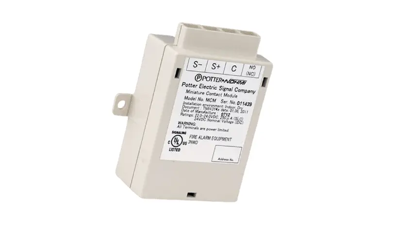
Description
The miniature contact module (MCM) module is used to monitor the contact status of an initiating device that contains a normally open contact. When the Normally-open contact is selected, and the contact is shorted, the MCM reports its condition to FACP. The MCM supervises an open circuit of wiring connected to the terminal C and NO.
The MCM is generally used to monitor pull stations and other devices where the module is installed in an electrical box or enclosure. The contact utilizes a terminal block that is covered in accordance with UL requirements to protect from inadvertent shorts and ground faults.
Setting the Address
Each addressable module, smoke sensor, heat detector and combination sensor/detector must have the address set prior connecting the device to the SLC loop. The address is set using the hand held device programmer.
Prior to connecting a device to the SLC loop, the following precautions should be taken to prevent potential damage to SLC or device. Verify the following before proceeding. Document discrepancies and notify appropriate personnel.
- Power in the Addressable Module is removed
- Field wiring on the module is correctly installed.
- Field wiring has no open or short circuits
Wiring diagram
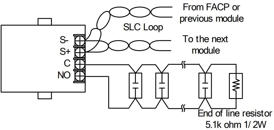
Figure 1: Wiring diagram in case of supervising Normally-open contact
Note
- SLC wiring style is applicable to the NFPA Class A (Style 6, 7) & Class B (Style 4).
- IDC wiring style is applicable to the NFPA Class B (Style B).
- SLC loop wiring (S+, S-) and initiating device wiring (C, NO) are power limited.
- Wiring for terminals S+, S- are supervised.
- Wiring for terminals C, NO are supervised.
- This addressable module does not support 2-wire detectors.
- All wiring is between #14 (2.08 mm2 ) (max.) and #22 (0.32 mm2 ) (min.).
- Wire Preparation Strip all wires 1/4 inch from their edges as follows:


Note
- a) Stripping too much insulation may cause ground fault
- b) Stripping too little may cause a poor connection and subsequently an open circuit
Specifications
| No | Item | Specification |
| 1 | Rated voltage range of SLC input power (S+,S-) | 22.0 to 24.0V |
| 2 | Maximum SLC 24 VDC standby current (S+,S-) | 250μA |
| 3 | Maximum SLC 24 VDC alarm current (S+,S-) | 250μA |
| 4 | IDC input circuit wiring style | Class B (Style B) |
| 5 | End-of-line resistor for IDC | 5.1kΩ,1/2W |
| 6 | Maximum wiring resistance of IDC | 100Ω |
| 7 | Maximum wiring capacitance of IDC | 1μF |
| 8 | Operating temperature range | 32 to 120°F (0 to 49°C) |
| 9 | Operating humidity range | 0 to 93% (non-condensing) |
| 10 | Maximum no. of module per loop | 127 units |
| 11 | Dimensions | 2.58”(65.5mm) (H) × 2.32”(59mm) (W) × 0.94”(24mm) (D) |
| 12 | Applicable electrical box for installation | 2-1/2”(64mm)deep single-gang box |
These instructions do not purport to cover all the details or variations in the equipment described, nor provide for every possible contingency to be met in connection with instillation, operation and maintenance. Specifications subject to change without prior notification For Technical Assistance contact Potter Electric Signal Company at 800-325-3936 Actual performance is based on proper application of the product by a qualified professional. Should further information be desired or should particular problems arise, which are not covered sufficiently for the purchaser’s purpose, the matter should be referred to No hmi or a distributor in your region.
Support
Potter Electric Signal Company, L LC 1609 Park 370 Place, Hazelwood, MO 63042 USA
Telephone: (866)956-1211
URL: http://www.pottersignal.com
![]()


