POTTER PAD100-ZM Conventional Zone Module
Features
- Compatible with conventional 2-wire smoke detectors
- IDC can be wired One (1) Class A or Two (2) Class B
- Monitors presence of 24VDC Aux Power
- SLC Class A, Class X & Class B
- Mounts in a standard 4” or double gang box
- Wiring terminals accessible when mounted in box
- All wiring terminals accept 22 to 12AWG
- Product includes a 5 year warranty
- UUKL Listed for Smoke Control
Description
The PAD100-ZM module uses one (1) address on an SLC Loop when monitoring two (2) Class B or one (1) Class A circuit. The module requires and supervises a 24VDC auxiliary power connection. The 24VDC power source must be either a Potter IPA series addressable panel, or a Potter PSN series power supply. The IDC may be wired Class B or Class A which is selectable by an on board DIP switch. The PA D100-ZM employs one red LED to indicate the module’s status. In normal condition, the LED flashes when the device is being polled by the control panel. When a device is activated, the LED will flash at a fast rate.
Application
The PAD100-ZM is compatible with Potter’s IPA and AFC/ARC series addressable fire alarm control panels. The PAD100-ZM is used to supervise a zone of conventional 2-wire smoke detectors on an Initiating Device Circuit (IDC). The PA D100-ZM is capable of monitoring two (2) separate Class B or one (1) Class A circuits.
Setting the Address
Each addressable SLC device must be assigned an address. The address is set using the DIP switch located on the PA D100-ZM. When the PAD100-ZM is used to monitor two individual Class B circuits a single device address is assigned, each input is then identified as a sub-point of the module address. For example, if the address number is assigned as “8”, the B1 input will be “8.1” and the B2 input will be “8.2”.
Before connecting a device to the SLC loop, take the following precautions to prevent potential damage to the panel or device:
- Power to the device is removed.
- Field wiring is correctly installed.
- Field wiring has no open or short circuits.
Technical Specifications
| Operating Voltage | 24.0V |
| Max SLC Standby Current | 240μA |
| Max SLC alarm Current | 240μA |
| aux power Required | 19 – 28V |
| Max Detector Standby Current of IDC at 24 VDC | 1ma |
| Max Module alarm Current of IDC at 24 VDC | 50ma |
| Max Wiring Resistance of IDC | 100Ω |
| Max Wiring Capacitance of IDC | 1μF |
| eOL Resistor | 5.1K Ω |
| Operating Temperature Range | 32 to 120ºF (0 to 49ºC) |
| Operating Humidity Range | 0 to 93% (non-condensing) |
| Max no. of Module per Loop | 127 units |
| Dimensions | 4.17” (106mm)L × 4.17” (106mm)W × 1.14” (29mm)D |
| Mounting Options | Standard 4” Square or Double gang Box |
| Shipping Weight | 0.6 lbs |
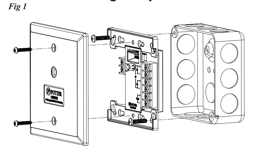
Installation Using Compatible Electrical Box
Wiring Diagrams
Typical Class B Wiring Diagram
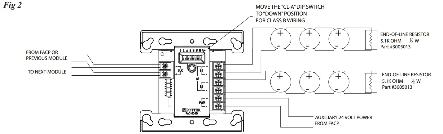
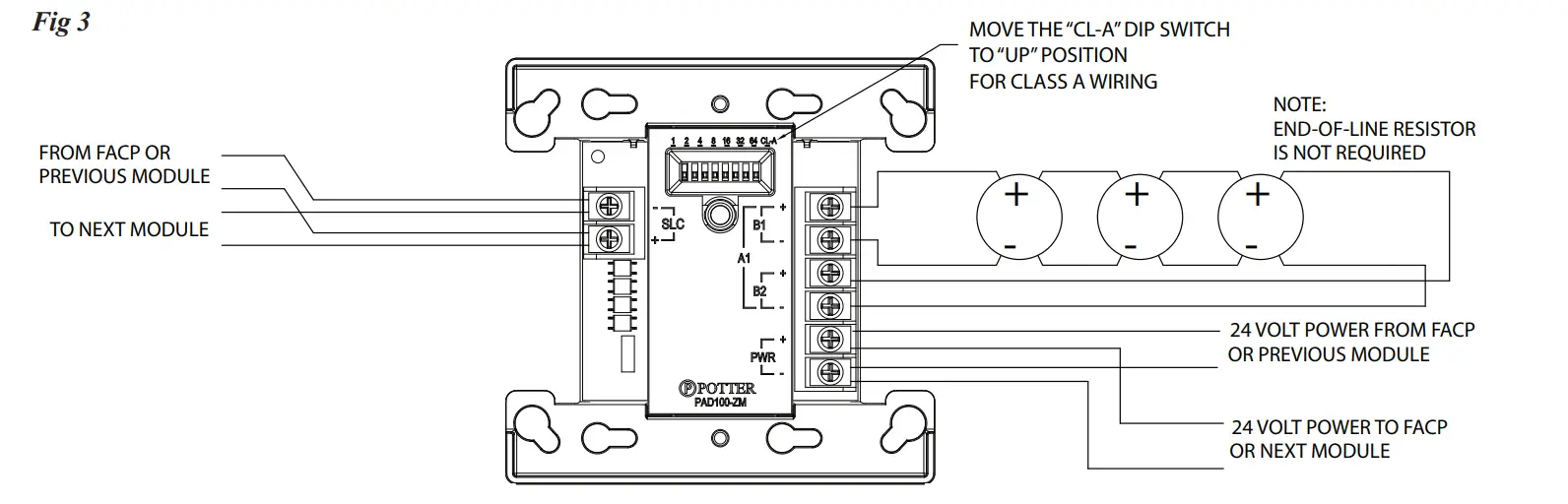
Typical Class A Wiring Diagram
Ordering Information
| Model | Description | Stock No. |
| paD100-ZM | Conventional Zone Module | 3992706 |
Compatible 2-Wire Smoke Detectors & Bases
| Detector Model | Identifier | Base Model | Identifier |
| SYSTEM SENSOR (Brk) (Max. No. Of Detectors Per Zone is 10) | |||
| 1400 | a | N/a | N/a |
| 2400 | a | N/a | N/a |
| 2400TH | a | N/a | N/a |
| 2W-B | a | N/a | N/a |
| 2WT-B | a | N/a | N/a |
| DETECTION SYSTEM (Max. No. Of Detectors Per Zone is 11) | |||
| DS250 | a | MB2W/MB2WL | a |
| DS250TH | a | MB2W/MB2WL | a |
| ESL (Max. No. Of Detectors Per Zone is 20) | |||
| 611U | S10 | 601U | S00 |
| 611UD | S10 | 601U | S00 |
| 611UT | S10 | 601U | S00 |
| 612U | S10 | 601U | S00 |
| 612UD | S10 | 601U | S00 |
| 613U5 | S10 | 601U | S00 |
| 611UD | S10 | 609U10 | S00 |
| 612UD | S10 | 609U10 | S00 |
| 425C | S10 | N/a | N/a |
| 425CT | S10 | N/a | N/a |
| HOCHIKI (Max. No. Of Detectors Per Zone is 20) | |||
| SLR-24 | HD-3 | HSC-221R | HB-71 |
| HSB-221 | HB-54 | ||
| HSB-221N | HB-54 | ||
| NS6-221 | |||
| NS4-221 | |||
| NS6-220 | HB-3 | ||
| SLR-24H | HD-3 | HSC-221R | HB-71 |
| HSB-221 | HB-54 | ||
| HSB-221N | HB-54 | ||
| NS6-221 | |||
| NS4-221 | |||
| SIJ-24 | HD-3 | HSC-221R | HB-71 |
| HSB-221 | HB-54 | ||
| HSB-221N | HB-54 | ||
| NS6-221 | |||
| NS4-221 | |||
| Detector Model | Identifier | Base Model | Identifier |
| FENWAL (Max. No. Of Detectors Per Zone is 14) | |||
| CpD-7051 | I51Fe1 | 2-WIRe | Fe51a |
| pSD-7155 | p55Fe1 | 2WRLT | Fe52a |
| pSD-7156 | p56Fe1 | 2WRB | Fe55a |
| all of the above Fenwal detectors and bases can be used in any combination. Retrofit Base Adaptor 70-501000-003, Identifier MAFE1 (for series 70-201000 Bases, Models -001, -002, -003, and -005). Duct Housing with Detector Base DH-51, Identifier DH22FE5 (for CPD-7051 and PSD-7155 detectors only). | |||
| POTTER (Max. No. Of Detectors Per Zone is 25) | |||
| pS-24 | HD-3 (HOCHIKI) | SB-46 | HB-71(HOCHIKI) |
| HB-54 (HOCHIKI) | |||
| SB-93 | HB-3 (HOCHIKI) | ||
| pS-24H | HD-3 (HOCHIKI) | SB-46 | HB-71 (HOCHIKI) |
| HB-54 (HOCHIKI) | |||
| IS-24 | HD-3 (HOCHIKI) | SB-46 | HB-71 (HOCHIKI) |
| HB-54 (HOCHIKI) | |||
| NOTE: If using a mix of System Sensor and other smoke detectors, a maximum of 20 detectors shall be permitted. | |||
CUSTOMER SUPPORT
Potter Electric Signal Company, LLC • St. Louis, MO • Phone: 800-325-3936 • www.pottersignal.com