TRANE X13790992 Residential Touch Screen Programmable Zone Sensor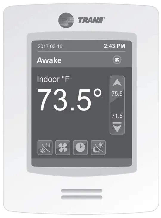
Introduction
Warnings, Cautions, and Notices
Safety advisories appear throughout this manual as required. Your personal safety and the proper operation of this machine depend upon the strict observance of these precautions.
The three types of advisories are defined as follows:
![]() WARNING Indicates a potentially hazardous situation which, if not avoided, could result in death or serious injury.
WARNING Indicates a potentially hazardous situation which, if not avoided, could result in death or serious injury.
![]() CAUTION Indicates a potentially hazardous situation which, if not avoided, could result in minor or moderate injury. It could also be used to alert against unsafe practices.
CAUTION Indicates a potentially hazardous situation which, if not avoided, could result in minor or moderate injury. It could also be used to alert against unsafe practices.
NOTICE Indicates a situation that could result in equipment or property-damage only accidents.
Important Environmental Concerns
Scientific research has shown that certain man-made chemicals can affect the earth’s naturally occurring stratospheric ozone layer when released to the atmosphere. In particular, several of the identified chemicals that may affect the ozone layer are refrigerants that contain Chlorine, Fluorine and Carbon (CFCs) and those containing Hydrogen, Chlorine, Fluorine and Carbon (HCFCs). Not all refrigerants containing these compounds have the same potential impact to the environment. Trane advocates the responsible handling of all refrigerants-including industry replacements for CFCs and HCFCs such as saturated or unsaturated HFCs and HCFCs.
Important Responsible Refrigerant Practices
Trane believes that responsible refrigerant practices are important to the environment, our customers, and the air conditioning industry. All technicians who handle refrigerants must be certified according to local rules. For the USA, the Federal Clean Air Act (Section 608) sets forth the requirements for handling, reclaiming, recovering and recycling of certain refrigerants and the equipment that is used in these service procedures. In addition, some states or municipalities may have additional requirements that must also be adhered to for responsible management of refrigerants. Know the applicable laws and follow them.
SAFETY WARNING
Only qualified personnel should install and service the equipment. The installation, starting up, and servicing of heating, ventilating, and air-conditioning equipment can be hazardous and requires specific knowledge and training.
Improperly installed, adjusted or altered equipment by an unqualified person could result in death or serious injury.
When working on the equipment, observe all precautions in the literature and on the tags, stickers, and labels that are attached to the equipment.
![]() WARNING
WARNING
Proper Field Wiring and Grounding Required!
Failure to follow code could result in death or serious injury. All field wiring MUST be performed by qualified personnel. Improperly installed and grounded field wiring poses FIRE and ELECTROCUTION hazards. To avoid these hazards, you MUST follow requirements for field wiring installation and grounding as described in NEC and your local/state/national electrical codes.
![]() WARNING
WARNING
Personal Protective Equipment (PPE) Required!
Failure to wear proper PPE for the job being undertaken could result in death or serious injury.
Technicians, in order to protect themselves from potential electrical, mechanical, and chemical hazards, MUST follow precautions in this manual and on the tags, stickers, and labels, as well as the instructions below:
- Before installing/servicing this unit, technicians MUST put on all PPE required for the work being undertaken (Examples; cut resistant gloves/sleeves, butyl gloves, safety glasses, hard hat/bump cap, fall protection, electrical PPE and arc flash clothing). ALWAYS refer to appropriate Safety Data Sheets (SDS) and OSHA guidelines for proper PPE.
- When working with or around hazardous chemicals, ALWAYS refer to the appropriate SDS and OSHA/GHS (Global Harmonized System of Classification and Labeling of Chemicals) guidelines for information on allowable personal exposure levels, proper respiratory protection and handling instructions.
- If there is a risk of energized electrical contact, arc, or flash, technicians MUST put on all PPE in accordance with OSHA, NFPA 70E, or other country-specific requirements for arc flash protection, PRIOR to servicing the unit. NEVER PERFORM ANY SWITCHING, DISCONNECTING, OR VOLTAGE TESTING WITHOUT PROPER ELECTRICAL PPE AND ARC FLASH CLOTHING. ENSURE ELECTRICAL METERS AND EQUIPMENT ARE PROPERLY RATED FOR INTENDED VOLTAGE.
![]() WARNING
WARNING
Follow EHS Policies!
Failure to follow instructions below could result in death or serious injury.
- All Trane personnel must follow the company’s Environmental, Health and Safety (EHS) policies when performing work such as hot work, electrical, fall protection, lockout/tagout, refrigerant handling, etc. Where local regulations are more stringent than these policies, those regulations supersede these policies.
- Non-Trane personnel should always follow local regulations.
![]() WARNING
WARNING
Take Precautions During Installation!
If replacing an existing sensor, label the wires before removal. Electronic controls are staticsensitive devices. Properly discharge yourself before manipulating and installing the sensor.
![]() WARNING
WARNING
Protecting the System!
All sensors are designed for use as operating units only and are not safety devices. Tampering with the device or unintended application of the device will void the warranty.
Copyright
This document and the information in it are the property of Trane, and may not be used or reproduced in whole or in part without written permission. Trane reserves the right to revise this publication at any time, and to make changes to its content without obligation to notify any person of such revision or change.
Trademarks
All trademarks referenced in this document are the trademarks of their respective owners.
Revision History
- Updated Specifications chapter.
- Running edits.
Equipment/Software Supported
The zone sensor will work with Trane fan coil, blower coil, unit ventilator, and water source heat pump equipment that uses the Trane UC400 control system.
Installation and Guidelines
- Do not install on an outside wall.
- Do not install in areas with direct heat source.
- Do not install near any air discharge grill.
- Do not install in areas exposed to direct sunlight.
- Ensure the sensor has sufficient air circulation.
- Ensure the mounting wall surface is flat and clean.

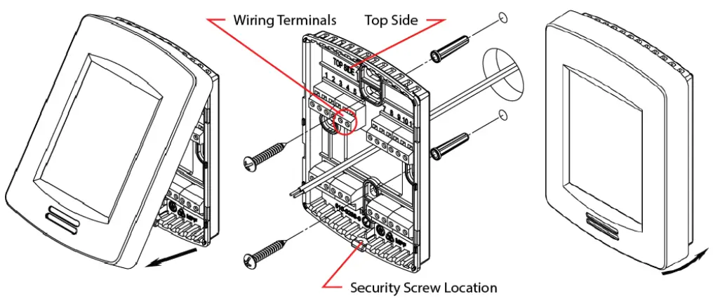
- Remove the security screw from the bottom of the sensor (if present).
- Firmly grasp the sensor and pull up on the bottom to remove the sensor from the baseplate.
- Drill a 1.5-inch diameter hole in the wall where the sensor will be located.
- Feed the power/communication wires through the hole.
- Strip the wire coating ends approximately 0.25 inch.
- Loosely install an EMI choke on each wire as shown in the wiring diagrams.
Note: Wire must make two complete wraps around each choke. - Feed the wires through the middle of the baseplate.
- Insert the wires into the wire terminals (per terminal identification in wiring diagrams) and tighten down the terminal screws to secure the wires.
- Slide each EMI choke along wires toward the baseplate until they are approximately a distance of 2 inches.
Note: Gently pull on both ends of each wire so they are snug around each choke. - Feed each wire/choke back into the hole so the baseplate can be mounted flush to the wall.
- Center the baseplate over the hole and ensuring correct orientation.
Note: TOP is embossed on baseplate to indicate proper orientation. - Vertically align the baseplate and mark the top/bottom mounting hole locations on the wall.
- Install the provided wall anchors and affix the baseplate to wall with the wall anchors screws.
- Attach the sensor to the baseplate by aligning the tabs at the top edge of the sensor with the notches at the top of the baseplate. Press down on the bottom half of the sensor to snap into place. The device will power up after applying power.
- Install the security screw on the bottom of the sensor to avoid tampering.
Wiring and Power
Suggested Supplier: Windy City Wire
- Plenum rated P/N: 043005AL
- Non-plenum rated P/N: 108760
Symbio™ 400/UC400 Terminal Block and Wiring to Sensor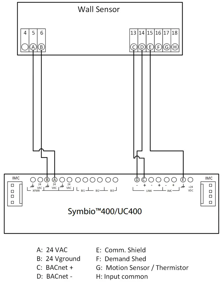
Symbio™ 400/UC400-B Terminal Block and Wiring to Sensor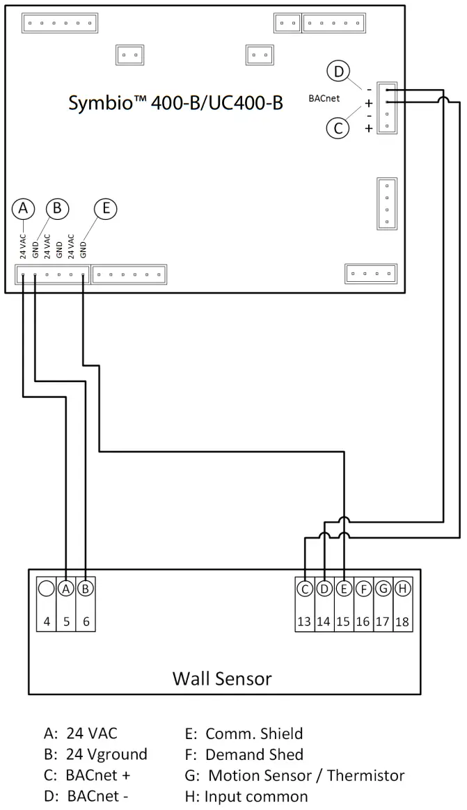
General Information
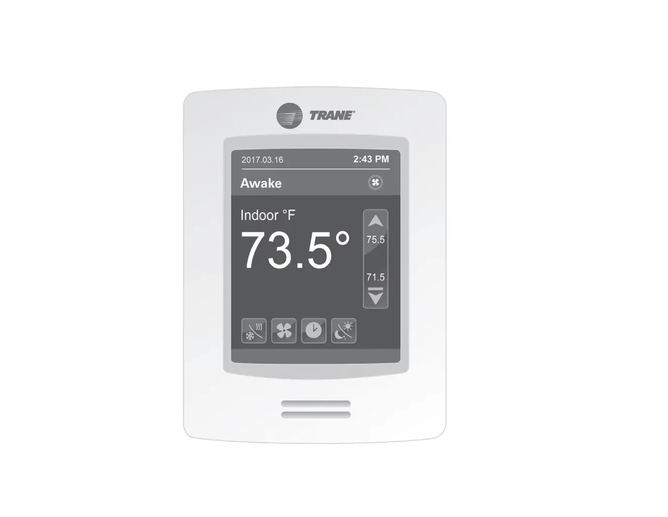
The sensor displays Power on during initial power-up and advances to display the Home Screen.
All user accessible functions are easily set from the Home screen: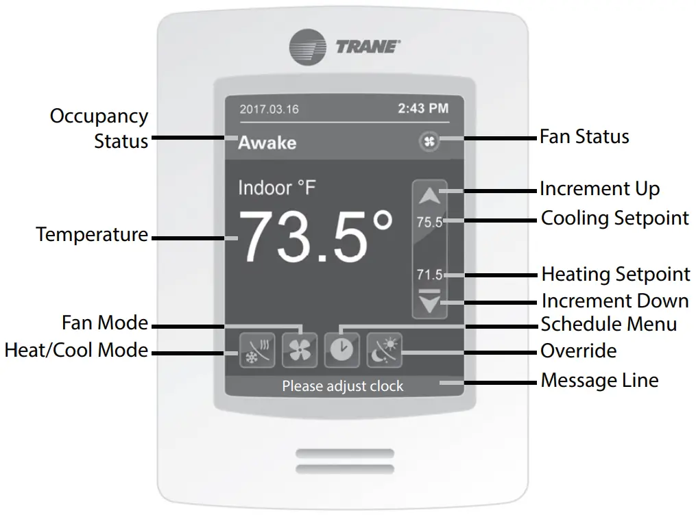
- Occupancy Status: displays either Awake, Away, Home, Sleep, Temp.Hold, Perm.Hold, or Vacation to indicate current occupancy mode.
- Fan Status: when fan is running, exterior circle indicates current fan speed.
- No Segments: Fan is OFF
- One Segment: 1% to 33%
- Two Segments: 34% to 66%
- Three Segments: 67% to 100%
- Setpoints: When Heat/Cool Mode is Cool Only or Heat Only, the current setpoint in use is displayed in the center of the setpoint control bar.
When mode is Auto or Off, the cooling setpoint is displayed just below the red bar and the heating setpoint is displayed just above the blue bar. - Message Line: provides information regarding the current state of the equipment. One of two messages may be displayed:
- Please adjust clock
- Vacation mode
- Temperature sensor failure
- Single touch of
 or advances the setpoint value by one. Holding down or rapidly advances through the available range of values.
 - If configured to do so, the Home screen will revert to a blank standby screen after 2.5 minutes of user inactivity.
- All settings are retained in sensor memory in the event of a power outage.
- Temperature: displays either the current space temperature or the temperature setpoint currently being used to condition the space.
Configuring Settings on the Home Screen
Cool/Heat Mode![]()
- Off: the system will not cool or heat the space.
- Auto: the system switches between cooling and heating automatically to condition the space.
- Cool: the system will only provide cooling to the space.
- Heat: the system will only provide heat to the space.
Fan Mode![]()
- Auto: the system fan runs only when there is a call for either cooling or heating.
- On: the system fan runs continuously in Awake, Return, and Sleep mode. The fan runs when there is only a call for either cooling or heating in Away mode.
Schedule Menu![]()
Touch![]() to advance to the Schedule Menu to set Clock, Schedule, Display, Setpoints, Vacation, and Options.
to advance to the Schedule Menu to set Clock, Schedule, Display, Setpoints, Vacation, and Options.
Override![]()
Touch ![]() to switch between, temporary override, permanent override, and schedule control.
to switch between, temporary override, permanent override, and schedule control.
Touch Button Legend
![]() Return to Home screen.
Return to Home screen.![]() Previous and Next screen advancement.
Previous and Next screen advancement.![]() Change setting values.
Change setting values.![]() Reset the instance number on 2/2 Network Instance screen.
Reset the instance number on 2/2 Network Instance screen.![]() Confirms the change to instance number.
Confirms the change to instance number.
Interface Flowcharts
User Menus
Touch the Schedule Menu button on the display to setup, Clock, Schedule, Setpoints, Vacation, and Options.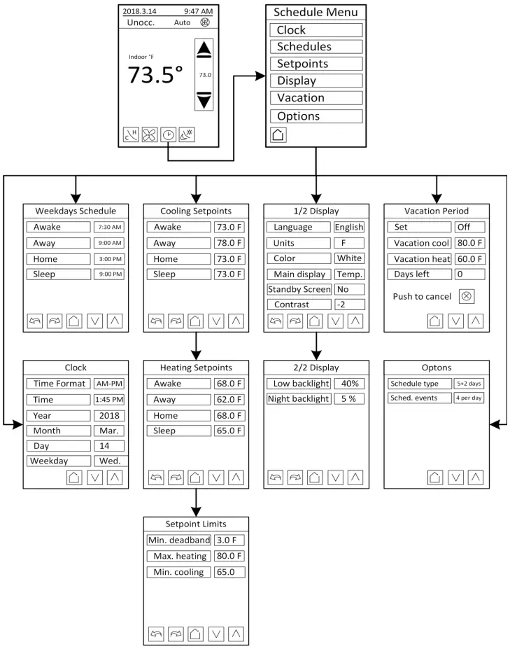
Clock, Schedule, Setpoints, Display, Vacation, and Options
| Clock | Configures the following:
|
| Schedule | Set the schedule time values that define when the sensor transitions from the current state to the next state. Note: Schedule format is set via the Options menu. |
| Setpoints | Configures Cooling and Heating setpoints and setpoint limits.
|
| 1/2 Display | Configure the format of the sensor Home screen and user interface.
|
| 2/2 Display | Low backlight:
|
| Vacation | Configures the cooling/heating setpoints and the number of days to be applied.
|
| Options | Schedule type:
Sched. events: configure unit to display either 2 or 4 events per day. |
Installer Menus
Note: The Installer password is 4017 and cannot be changed.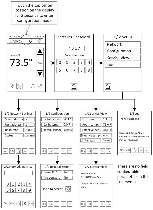
Configuring the Sensor
Network
Device Addressing
To correctly configure the BACnet MS/TP network, perform the following actions:
- With the UC400/UC400-B powered down, set the rotary address of the UC400/UC400-B to 1. Once address has been set, apply power to the UC400.
- Using the sensor display, set the Sens. Address field to a value of 2.
- Using the sensor display, set the Unit Address field to the same value as the UC400/UC400-B rotary address 1.
- Set the network instance number to same value as the sensor address field 2.
Sens. Address Sets the sensor BACnet MAC address. (Range of 0-127) Unit address BACnet address of the UC400/UC400-B (range of 0-127). Baud rate Sets the baud rate. Default is 76800 (leave default value unless directed by Trane Technical Support). Status This setting is not configurable. It indicates that BACnet communication is occurring between the UC400/UC400-B and the sensor. 2/2 Network Instance Use the number pad to set the BACnet Device ID of the sensor. Touch to Confirm and Save the value. (Range 0 – 4194302) Touching R on this screen copies the sensor MAC address number to the BACnet Device ID field. For example, if the MAC address = 7, touching R sets the Device ID number to 7.
Configuration/Reinitialization
| Installer pwd | The installer password is fixed at the value 4017 and cannot be changed. |
| Calib. temp. | Provides a means to adjust the raw value measured by the temperature sensor internal to the device. Used to calibrate the sensor to an external reference value. |
| Temp. sensor | Selects the location of the space temperature sensor. For residential applications it should always be set to Internal. Other options are remote and wired. |
| Erase all? | Resets the sensor back to factory settings. |
| Are you sure? | Confirms the erase reset. |
Service View
| 1/2 Service View |
|
| 2/2 Service View |
|
LUA
The LUA setting screens display information about custom LUA scripts uploaded into the sensor. These screens are not used.
Specifications
| Sensor Operating Temperature | 32°F to 122°F (0°C to 50°C) |
| Storage Temperature | –22°F to 122°F (–30°C to 50°C) |
| Storage and Operating Humidity Range | 0% to 95%, non-condensing |
| Temperature Control Accuracy | +/- 0.9°F (+/– 0.5°C) @ 70F (21°C) typical calibrated |
| Temperature Sensor Resolution | +/– 0.2°F (+/–0.1°C) |
| Room Air Temperature Display Range | –40°F to 122°F (–40°C to 50°C) |
| Occupied/Unoccupied Setpoint Range |
|
| Heating/Cooling Setpoint Minimum Deadband | 2°F to 5°F (1.0°C to 2.5°C) |
| Power Supply | 24 Vac (19–30 Vac), 50 Hz or 60 Hz, Class 2 |
| Power Wire | 18 AWG or Larger |
| Power Consumption | 6 VA |
| Housing |
|
| Weight | 0.75 lb. (0.34 kg) |
| Mounting | 3.24 in (8.26 cm) for 2 mounting screws (supplied) |
| Communication Wire |
|
|
Standards |
|
| RoHS Compliance | Enclosure and components are RoHS compliant (RoHS 2002/95/EC) |
![]() WARNING
WARNING
Cancer and Reproductive Harm!
This product can expose you to chemicals including lead and bisphenol A (BPA), which are known to the State of California to cause cancer and birth defects or other reproductive harm.
For more information, go to www.P65Warnings.ca.gov.
Trane – by Trane Technologies (NYSE: TT), a global climate innovator – creates comfortable, energy efficient indoor environments for commercial and residential applications. For more information, please visit trane.com or tranetechnologies.com.
Trane has a policy of continuous product and product data improvement and reserves the right to change design and specifications without notice. We are committed to using environmentally conscious print practices.