![]() ULXB Series
ULXB Series
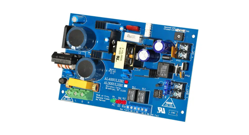
AL400ULXB2 UL Listed Sub-Assembly Power Supply/Charger Boards
Installation Guide
Models Include:
| AL400ULXB2 – 12 @ 4A or 24VDC @ 3A | AL1012ULXB – 12VDC @ 10A |
| AL600ULXB – 12 or 24VDC @ 6A | AL1024ULXB2 – 24VDC @ 10A |
Installation Guide
![]() Rev. ULXB-020419
Rev. ULXB-020419
Overview:
Altronix ULXB power supply/chargers convert a 115VAC / 60Hz input to a 12VDC or 24VDC output.
Agency Listings:
| Altronix Model Number | |||||
| UL294* Access Control | UL603 | UL1069 Hospital Signaling and Nurse Call | UL1481 Fire Alarm | CSA C22.2 No.205-M1983 Signal Equipment | |
| AL400ULXB2 | |||||
| AL600ULXB | N/A | ||||
| AL1012ULXB | N/A | N/A | N/A | ||
| AL1024ULXB2 | N/A | ||||
| Altronix Model Number | * ANSI/UL 294 7th Ed. Access Control Performance Levels | |||
| Destructive Attack | Endurance Test | Line Security | Standby Power | |
| AL400ULXB2 | N/A – sub-assembly | IV | I | II |
| AL600ULXB | N/A – sub-assembly | IV | I | IV |
| AL1012ULXB | I | I | I | II |
| AL1024ULXB2 | N/A – sub-assembly | IV | I | IV |
Specifications:
| Altronix Model Number | Input Rating 115VAC 60Hz | Output Voltage (Current) | Class 2 Power- Limited Output | Maximum Charge Current | |
| 12VDC | 24VDC | ||||
| AL400ULXB2 | 3.5A | 4A | 3A | 0.7A | |
| AL600ULXB | 3.5A | 6A | 6A | –* | 0.7A |
| AL1012ULXB | 2.6A | 10A | – | –* | 0.7A |
| AL1024ULXB2 | 4.2A | – | 10A | –* | 3.6A |
All of the above UL Listed Sub-Assembly Power Supply/Chargers can be installed in Trove1 and Trove2 Access and
Power Integration Systems and Maximal Series.
For UL603 applications, or if a power-limited output is required in the end-product application, the DC output from the power supply must be connected to a separately Listed control unit or accessory board that provides power-limited outputs. The product(s) providing the power-limited output(s) must be listed as appropriate for the particular end-product application (fire alarm, burglar alarm, access control) and wired in accordance with the product’s installation instructions. Class 1 wiring methods, separation of circuits, and proper fire-rated enclosures all must be considered when connecting the DC output of the power supply to the end-product devices. The auxiliary outputs of these units are
power-limited.
Specifications (cont’d):
Output:
- Filtered and electronically regulated output. Battery Backup:
- Built-in charger for sealed lead acid or gel type batteries.
- Automatic switch over to stand-by battery when AC fails.
- Zero voltage drop when switched over to battery backup.
Supervision:
- AC fails supervision (form “C” contacts).
- Low battery and battery presence supervision (form “C” contacts).
Visual Indicators:
- AC input, DC output, and BAT trouble LED indicators.
Additional Features: - Short circuit and thermal overload protection. Board Dimensions (L x W x H approximate):
AL400ULXB2:
7.1” x 4.5” x 1.44” (180mm x 114mm x 37mm).
AL600ULXB:
7.1” x 4.5” x 2” (180.3 mm x 114.3 mm x 50.8 mm).
AL1012ULXB:
7.25” x 4.5” x 1.75” (184.2mm x 114.3mm x 44.5mm).
AL1024ULXB2:
8.4” x 4.5” x 1.9” (213.4mm x 114.3mm x 48.3mm).
Stand-by Specifications:
AL400ULXB2:
| Output | Burg. Application 4 hr. of Stand-by/ 5 min. of Alarm | Fire Applications 24 hr. of Stand-by/ 5 min. of Alarm | 60 hr. of Stand-by/ 5 min. of Alarm* | Access Control Applications Stand-by |
| 12VDC / 40AH Battery | Stand-by = 4.0A Alarm = 4.0A | Stand-by = 1.0A Alarm = 4.0A | Stand-by = 300mA Alarm = 4.0A | 4 hrs./4A |
| 24VDC / 12AH Battery | – | Stand-by = 200mA Alarm = 3.0A | – | – |
| 24VDC / 40AH Battery | Stand-by = 3.0A Alarm = 3.0A | Stand-by = 1.0A Alarm = 3.0A | Stand-by = 300mA Alarm = 3.0A | 4 hrs./3A |
AL600ULXB:
| Output | Burg. Applications 4 hr. of Stand-by/ 5 min. of Alarm | Fire Applications 24 hr. of Stand-by/ 5 min. of Alarm | 60 hr. of Stand-by/ 5 min. of Alarm* | Access Control Applications Stand-by |
| 12VDC / 40AH Battery | Stand-by = 6.0A Alarm = 6.0A | Stand-by = 1.0A Alarm = 6.0A | Stand-by = 300mA Alarm = 6.0A | 4 hrs./6A |
| 24VDC / 12AH Battery | – | Stand-by = 200mA Alarm = 6.0A | – | – |
| 24VDC / 40AH Battery | Stand-by = 6.0A Alarm = 6.0A | Stand-by = 1.0A Alarm = 6.0A | Stand-by = 300mA Alarm = 6.0A | 4 hrs./6A |
AL1012ULXB:
| Output | Access Control Applications Stand-by |
| 12VDC / 12AH Battery | 30 minutes of backup @ 10A |
AL1024ULXB2:
| Output | 15 min. of Stand-by/ 5 min. of Alarm | Burg. Applications 4 hr. of Stand-by/ 5 min. of Alarm | Fire Applications 24 hr. of Stand-by/ 5 min. of Alarm | 60 hr. of Stand-by/ 5 min. of Alarm* | Access Control Applications Stand-by |
| 24VDC / 12AH Battery | Stand-By = 8A Alarm = 10A | Stand-By = 1.5A Alarm = 10A | Stand-By = 200mA Alarm = 10A | Stand-By = 100mA Alarm = 10A | 20 mins./8A |
| Output | 15 min. of Stand-by/ 5 min. of Alarm | Burg. Applications 4 hr. of Stand-by/ 5 min. of Alarm | Fire Applications 24 hr. of Stand-by/ 15 min. of Alarm | 60 hr. of Stand-by/ 15 min. of Alarm* | Access Control Applications Stand-by |
| 24VDC / 65AH Battery | – | Stand-By = 8.0A Alarm = 10A | Stand-By = 1.5A Alarm = 10A | Stand-By = 500mA Alarm = 10A | 4 hrs./8A |
Not evaluated by UL.
Installation Instructions:
Wiring methods shall be in accordance with the National Electrical Code/NFPA 70/NFPA 72/ANSI, the Canadian
Electrical Code and with all local codes and authorities having jurisdiction. The product is intended for indoor use only.
- Refer to Sub-Assembly Installation Instructions for mounting Rev. MS020119.
- Set desired DC output voltage by setting SW1 to the appropriate position on the power supply board (Fig. 1e, pg. 4).
- Connect unswitched AC power (115VAC 60Hz) to the terminals marked [L, N] (Fig. 1a, pg. 4). Use 14 AWG or larger for all power connections (Battery, AC input, DC output). Use 22 AWG to 18 AWG for power-limited circuits (AC Fail/Low Battery reporting).
Keep power-limited wiring separate from non-power-limited wiring (115VAC / 60Hz Input, DC Output (refer to Specifications Chart, pg. 2), Battery Wires). Minimum 0.25” spacing must be provided. CAUTION: Do not touch exposed metal parts. Shut branch circuit power before installing or servicing equipment. There are no user-serviceable parts inside. Refer installation and servicing to qualified service personnel. - Measure output voltage before connecting devices. This helps avoid potential damage.
- Connect devices to be powered to the terminals marked [+ DC –] (Fig. 1d, pg. 4).
- For Access Control applications batteries are optional. When batteries are not used, a loss of AC will result in the loss of output voltage. When the use of stand-by batteries is desired, they must be lead acid or gel type. Connect the battery to terminals marked [– BAT +] (Fig. 1c, pg. 4).
Note: Separate enclosures must be used for housing 40AH or 65AH batteries.
7. It is required to connect appropriate signaling notification devices to [AC FAIL] & [BAT FAIL] (Fig. 1b, pg. 4) supervisory relay outputs. Use 22AWG to 18AWG wires. AC fail will report in 5 minutes. To delay the report for 6 hours cut the “AC Delay” jumper (Fig. 1, pg. 4).
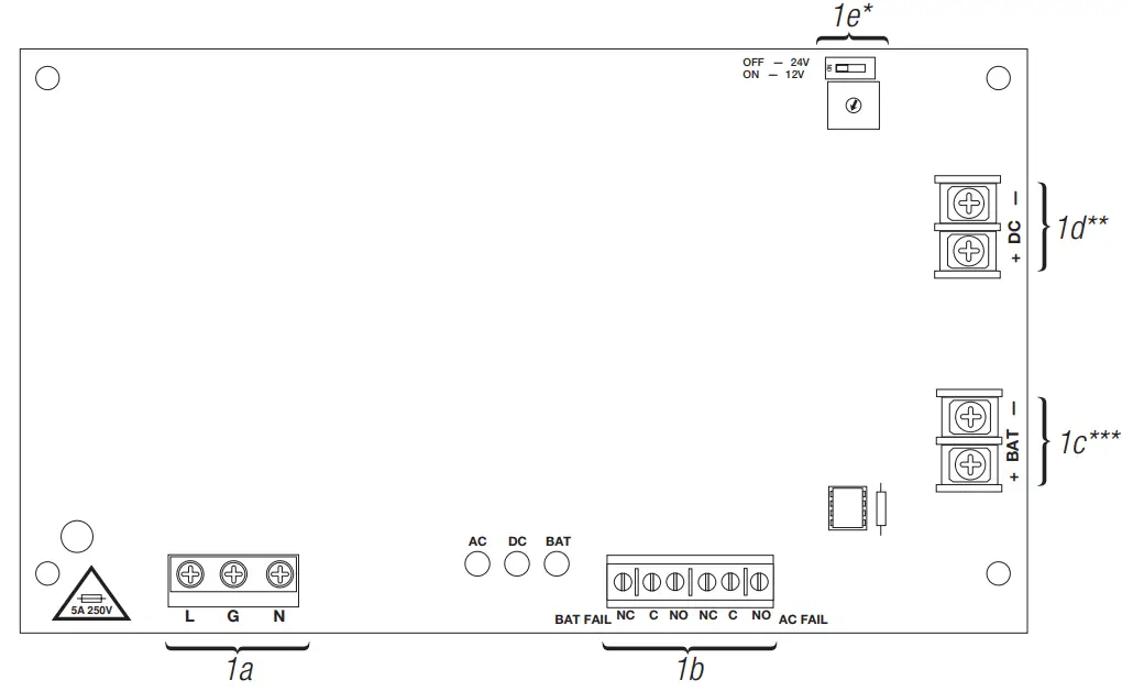
- Output Voltage Selection Dip Switch. Not applicable for AL1012ULXB and AL1024ULXB2.
- AL1012ULXB terminals marked [– DC +]
- AL1024ULXB2 terminals marked [– BAT +]
Wiring:
Use 18 AWG or larger for all low voltage power connections.
Note: Take care to keep power-limited circuits separate from non-power-limited wiring (120VAC, Battery).
Maintenance:
The unit should be tested at least once a year for the proper operation as follows:
Output Voltage Test: Under normal load conditions, the DC output voltage should be checked for proper voltage level.
Battery Test: Under normal load, conditions check that the battery is fully charged, and check the specified voltage (12VDC @ 13.2 or 24VDC @ 26.4) both at the battery terminal and at the board terminals marked [– BAT +] to ensure that there is no break in the battery connection wires.
Replacing Batteries: Disconnect existing batteries. Connect the battery to the terminals marked [– BAT +]. Use two (2) 12VDC batteries connected in series for 24VDC operation.
LED Diagnostics (AL400ULXB2 and AL600ULXB):
| Red (DC) | Green (AC) | Red (BAT) | Power Supply Status |
| ON | ON | ON | Normal operating condition. |
| ON | OFF | ON | Loss of AC. The standby battery is supplying power. |
| OFF | ON | OFF | No DC output, Battery Trouble. |
| OFF | OFF | OFF | Loss of AC. Discharged or no stand-by battery. No DC output. |
| ON | ON | OFF | The battery is missing / Low. |
LED Diagnostics (AL1012ULXB and AL1024ULXB2):
| Red (DC) | Green (AC) | Power Supply Status |
| ON | ON | Normal operating condition. |
| ON | OFF | Loss of AC. Stand-by is battery supplying power. |
| OFF | ON | No DC output. |
| OFF | OFF | Loss of AC. Discharged or no stand-by battery. No DC output. |
Terminal Identification:
| Terminal Legend | Function/Description |
| L, G, N | Connect 115VAC to these terminals: L to hot, N to neutral (Fig. 1a, pg. 4). |
| + DC – ** | AL400ULXB2: 12VDC @ 4A or 24VDC @ 3A continuous output (Power-Limited output) (Fig. 1d, pg. 4). AL600ULXB: 12VDC or 24VDC @ 6A continuous output (Non-Power-Limited output) (Fig. 1d, pg. 4). AL1012ULXB: 12VDC @ 10A continuous output (Non-Power-Limited output) (Fig. 1d, pg. 4). AL1024ULXB2: 24VDC @ 8A continuous, 10A in alarm (UL1481). 24VDC @ 10A (UL294) (Non Power-Limited output) (Fig. 1d, pg. 4). |
| AC FAIL NO, C, NC | Used to notify loss of AC power, e.g.connect to audible device or alarm panel. The relay is normally energized when AC power is present. Contact rating 1A @ 28VDC. AC or brownout fail is reported within 1 minute of the event. To delay reporting for up to 6 hrs., cut the “AC Delay” jumper and reset power to unit (Fig. 1b, pg. 4). |
| BAT FAIL NO, C, NC | Used to indicate low battery condition, e.g. connect to the alarm panel. Relay is normally energized when DC power is present. Contact rating 1A @ 28VDC. A removed battery is reported within 1 minute. Battery reconnection is reported within 1 minute. Low battery threshold: approximately 21VDC (Fig. 1b, pg. 4). |
| + BAT – *** | Stand-by battery connections (Fig. 1c, pg. 4). AL400ULXB2, AL600ULXB, AL1012ULXB maximum charge current 0.7A. AL1024ULXB2 maximum charge current 3.6A. |
- AL1012ULXB terminals marked [– DC +]
- AL1024ULXB2 terminals marked [– BAT +]
UL Model Reference Chart:
| UL Listed Sub-Assembly Board | Power Supply Series | Enclosures | |
| AL400ULXB2 | AL400ULX | Maximal11 | BC300, BC400, BC800 (Maximal), Trove1 and Trove2 |
| AL600ULXB | AL600ULX | Maximal33 | BC300, BC400, BC800 (Maximal), Trove1 and Trove2 |
| AL1012ULXB | AL1012ULX | Maximal55 | BC300, BC400, BC800 (Maximal), Trove1 and Trove2 |
| AL1024ULXB2 | AL1024ULX | Maximal77 | BC300, BC400, BC800 (Maximal), Trove1 and Trove2 |
Notes:![]()
Altronix is not responsible for any typographical errors.
140 58th Street, Brooklyn, New York 11220 USA
phone: 718-567-8181 fax: 718-567-9056
website: www.altronix.com
e-mail: [email protected] Lifetime Warranty IIULXB F22U


