
![]() UHP-1500 Series 1500W Conduction Cooling with PFC Switching Supply
UHP-1500 Series 1500W Conduction Cooling with PFC Switching Supply
Instruction Manual
![]()
![]()
Features
- Slim and Low profile (41mm)
- Fanless and conduction-cooled design
- Built-in active PFC function
- -30–+70 C working temperature
- Output voltage and constant current level programmable
- Protections: Short circuit / Overload / Over voltage / Over temperature
- Built-in remote ON-OFF control
- DC OK active signal
- Operating altitude up to 5000 meter (Note.9)
- LED indicator for power on
- Optional PMBus or CANBus protocol
- 5 years warranty
Applications
- Industrial automation machinery
- Industrial control system
- Mechanical and electrical equipment
- Electronic instruments, equipment or apparatus
- Test and measurement instrument
- Laser related machine
- Charging related equipment
- Household appliances
- Power Sourcing Equipment of PoE (48V model: DC 0/P range 48-57.6V)
Desri52 Search: httos:awavurtanitell.canrseniceGTIN.asox
Description UHP-1500 series is a 1500W single-output slim type power supply with 41mm of low profile design. Adopting the full range 90-264VAC input, the entire series provides an output voltage line of 24V and 48V. In addition to the high efficiency up to 96%, that the whole series operates from -30 C – 70’C under air convection without fan. UHP-1500 has the complete protection functions and 5G anti-vibration capability; It is complied with the international safety regulations such as TUV BS EN/EN62368-1, UL62368-1, and the design refers to BS EN/EN61558-1 and BS EN/EN60335-1. UHP-1500 series serves as a high performance power supply solution for various industrial applications.
Model Encoding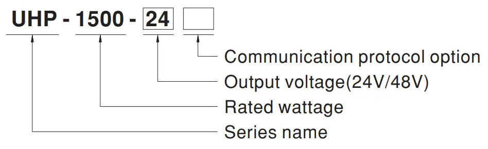
| Type | Communication Protocol | Note |
| Blank | None | In Stock |
| PM | PMBus protocol | By request |
| CAN | CAN Bus protocol | By request |
SPECIFICATION
| MODEL | UNP-150 0-24 | UHP-150 0-48 | |||
| OUTPUT | DC VOLTAGE | 24V | 48V | ||
| RATED CURRENT | 625A | 315A | |||
| RATED POWER | 15COW | 1512W | |||
| RIPPLE & NOISE (max.) Nott2 | 240mVp-p | 350mVp-p | |||
| VOLTAGE ADJ. RANGE | By built-ii potentiometer. SVR | ||||
| 24-28.8V | 48-57.6V | ||||
| VOLTAGE TOLERANCE Note3 | ±1.0% | 11.% | |||
| LINE REGULATION | ±0.5% | ±0.5% | |||
| LOAD REGULATION | ±0.5% | ±0.5% | |||
| SETUP, RISE TIME Note 4 | 1800ms, 60ms/230VAC 1800ms, 60ms/115VAC al full load | ||||
| HOLD UP TIME (Typ.) Note 4 | 16ms/2 30VAC at 75% load 10ms/230VAC at full bad: 1E4150115VAC at 75% load 10ms/115VAC at full load | ||||
| INPUT | VOLTAGE RANGE Note 4 | 90 – 264VAC 250 – 370VDC | |||
| FREQUENCY RANGE | 4 7 – 63Hz | ||||
| POWER FACTOR (Typ.) Nots.4 | PF ..?…0.95/230VAC PF ?-,0.99/115VAC at ful load | ||||
| EFFICIENCY (Typ.) | 95% 196% | ||||
| AC CURRENT (Typ.) | 11A/115VAC 8N230VAC | ||||
| INRUSH CURRENT (Typ.) | Cob start 30A/115VAC 6 0A/230VAC | ||||
| LEAKAGE CURRENT | <0.75mA/ 240VAC | ||||
| PROTECTION | OVERLOAD | 105-125% rated current | |||
| Protection type :Constant cur rent limiting. shut down 0/P voila° e after 5 sec. After O/P voltage fats. re-power an to recover | |||||
| SHORT CIRCUIT | Constant anent knit:1g , unit will shut down after 5sec, re-power on la motet. | ||||
| OVER VOLTAGE | 30 – 3W lee -67V | ||||
| Prelection type :Shut down OP vol tape, re-power an to recover | |||||
| OVER TEMPERATURE | Prelections type :Shut down O/P voltage, recovers automatically after le ape/alum 9014 down | ||||
| FUNCTION | OUTPUT VOLTAGE PROGRAMMABLE(PV) Note 5 | Adjustment of output voltage is allowable to 50- 120% of nominal output voltage Please refer to the Function Manual. | |||
| OUTPUT CURRENT PROGRAMMABLE(PC) Note 5 | Adjustment of constant current level is allowable to 1020- 100% of rated current. Flea se refer to the Function Manual. | ||||
| REMOTE ONIOFF CONTROL | Power ON: Short circuit Power OFF: Open circuit | ||||
| AUXILIARY POWER | 12V 00.4A tolerance ±10%, ripple=150mVp-p | ||||
| DC-OK SIGNAL | The TTL signal out, PSU turn co =4 A – 5.5V ; PSU turn off = -0.5- 0.5V. Please retort° the Function Manual. | ||||
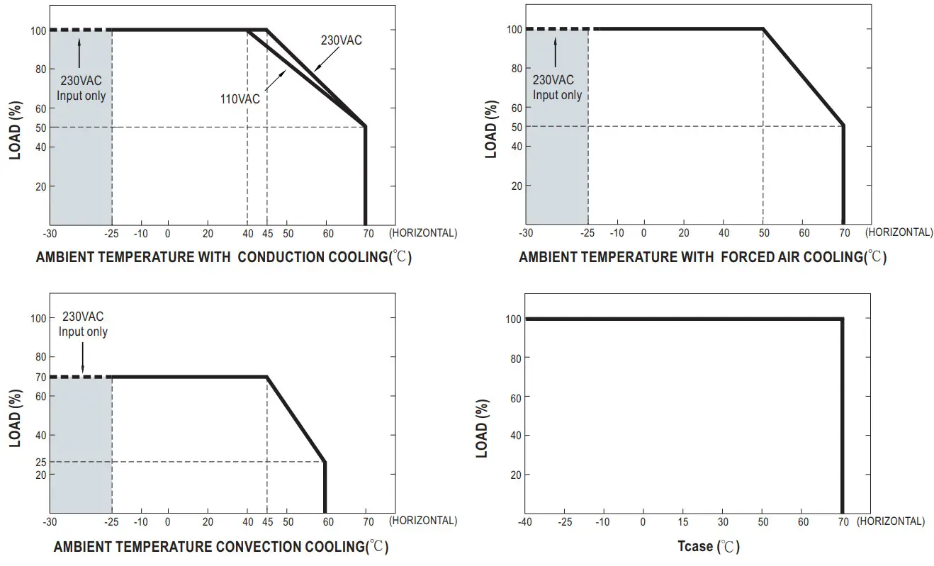
| ENVIRONMENT | WORKING TEMP. | -30- +70t (Refer b ‘Deming Curve”) | |||
| WORKING HUMIDITY | 20 – 93% RH non-condensing | ||||
| STORAGE TEMP.. HUMIDITY | -40- +85t , 10 -95% RH non-condensing | ||||
| TEMP. COEFFICIENT | 20.03%/C (0- 50.0 ) | ||||
| VIBRATION | 10- 50 0Hz. 5G 10min/1cycla, 60mb. each along X. Y, 2 axes | ||||
| SAFETY & EMC (ama) | SAFETY STANDARDS | UL62368-I. Debra seal BS B4IENE2368-1. EAC TP TC 004 approved. Design refers to 8.5 ENEN51558-I. BS ENEN60335-1(by reams° | |||
| WITHSTAND VOLTAGE | I/R093.7 5KVAC UP-FG:2KVAC O8-FG:1.25KVAC | ||||
| ISOLATION RESISTANCE | I/P-OP. 1/P-FGOP-FG:100k1 Ohms/500VDC125(2/ 70%RH | ||||
| EMC EMISSION | Parameter | Standard | Test Level / Note | ||
| Conducted | BS EINE N5 50 32 (CISPR3 2) | Cass B | |||
| Radiated | BS EN/EIL550 32 (CISPR3 2) | OassA | |||
| Harmonic Current | BS EN/EN6 10 00-3-2 | OassA | |||
| Voltage Flicker | BS EN/EN610 00-3-3 | — | |||
| EMC IWAUNITY | EIS EN/EN5503 5. 85 EN/EN6100 0-6-2 | ||||
| Parameter | Standard | Test Level / Nola | |||
| ESD | BS EN/EN610 00-4-2 | Level 3, 8KV 26f; Leve12,4KVccolali | |||
| Radiated | BS EN/EN61000-4-3 | Level 3 | |||
| EFT/Burst | BS EN/EN610 00-4-4 | Level 3 | |||
| Surge | BS EN/EN61000-6-2 | 2KV/Line-Line 4KVA.ine-Earth | |||
| Conducted | BS EIVEN610 00-4-6 | Level 3 | |||
| Magneto Field | BS EN/EN61003-4-8 | Level 4 | |||
| Voltage Dips and Interruptions | BS EN/EN610 00-4-11 | >95%ap0.5 periods. 30%6p 25 periods. >95% in le mplais 250 periods | |||
| OTHERS | MTBF | 53 5.4K hrs min. Telcordia SR-332 (Bellcore) ; 56.7K Ns min. MIL-EIDBK-217F (25’C) | |||
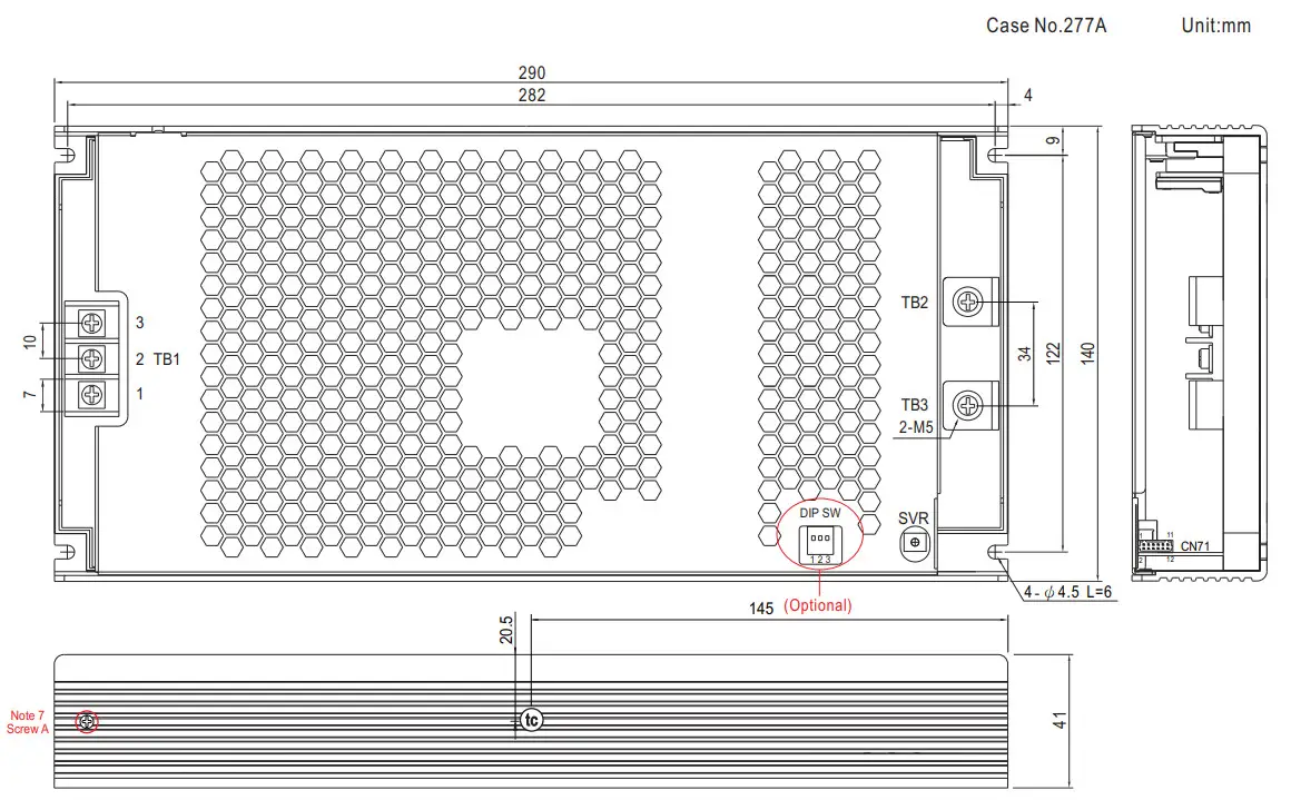
| DIMENSION | 29 0140%1mm (LIAM) | ||||
| PACKING | 2.51kg ;6pcs/16.06kg1036CUFT | ||||
| NOTE | 1.At parameters NOT specialty mentioned are measured at 29E1VAC irrupt rated load and 25 C of arolium temperature. 2.Ripple & noise are measured at 20MHz of bandwidth by using a 12′ twisted pair-wire terminated with a Olaf & 47ta parallel capacitor. 3.Tolerance :includes set up 10Ieran0a. line regulation and load regulation. 4.De rating may be needed under low input voltages. Please check the debiting curve and Static characteristics for more details. 5.PV/PC functions Mien users do not use SVR. 6.Output wit shut down after OP voltage is below < 80% of Vset for 5 sec. re-power on to recover. 7.To avoid damage to components a /mutations that are not involved in the test Its or the Ike. may be disconnected and equipotential bonding may be used A varistor complying with clause G.8 maybe removed during the test. 8.The power supply s considered a component which will be installed into a final equipment. Al be EMC tests are been executed by mounting the unit on a 720mm’360mm metal plate with 1mm of likeness. The final equipment must be re-confirmed that it still meets EMC directives. For guidance on how to perform these EMC tests, abase refer to ‘EMI testing of component power applies.’ (as amiable on http://www.meanavelcom) 9.The ambient temperature derating of 3.5’en 000m with fanless models and of 5 t/1000rti with tan models for operating attitude higher than 2 000m(6500fi). | ||||
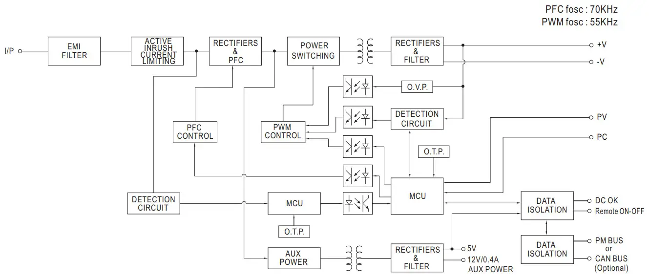
BLOCK DIAGRAM
STATIC CHARACTERISTIC
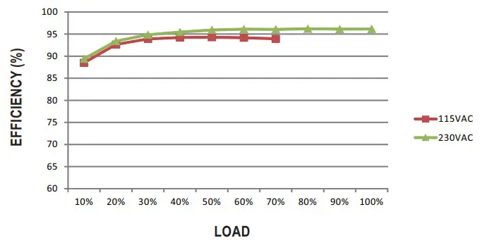
EFFICIENCY VS LOAD (48V MODEL)
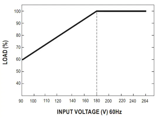
DERATING CURVE
FUNCTION MANUAL
1.Output Voltage Programming (or, PV / remote voltage programming / remote adjust / margin programming / dynamic voltage trim)
※ In addition to the adjustment via the built-in potentiometer, the output voltage can be trimmed by applying EXTERNAL VOLTAGE.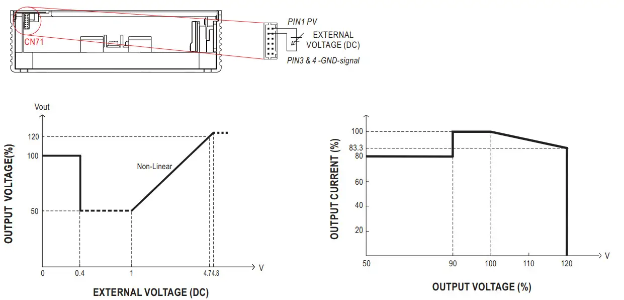 ◎ The rated current should change with the Output Voltage Programming accordingly.
2.Constant Current Programming (or, PC / remote current programming / dynamic current trim)
※ The output current can be trimmed to 20~100% of the rated current by applying EXTERNAL VOLTAGE.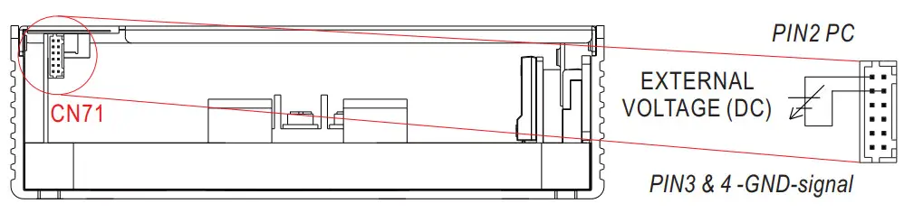 ◎ Output will shut down after O/P voltage is below < 80% of Vset for 5 sec, re-power on to recover.
※ Covered by over temperature protection, auto de-rating function works under operation either in PC mode or under control by communication protocol.
T1(Typ.): Maximum ambient temperature of full load.
T 2(Typ.) ℃ : T1+5.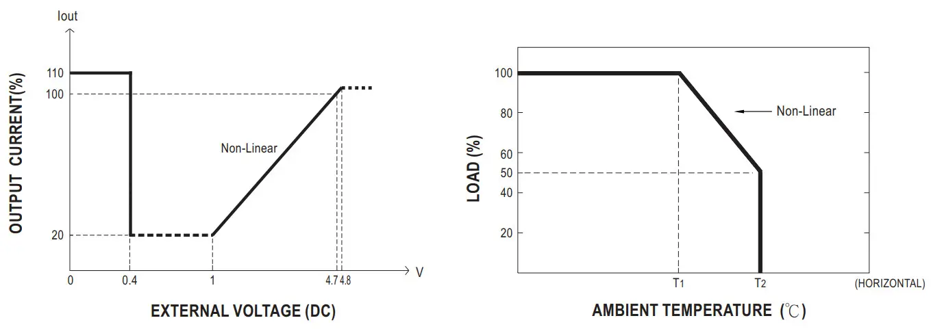 3.Remote ON-OFF Control
The power supply can be turned ON/OFF individually or along with other units in parallel by using the “Remote ON-OFF” function.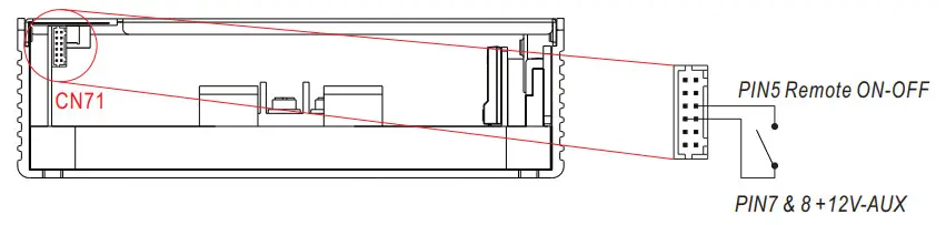
| Remote ON-OFF | Power Supply Status |
| Short circuit | ON |
| Open circuit | OFF |
4.DC-OK Signal
DC-OK signal is a TTL level signal. The maximum sink current is 10mA and the maximum external voltage is 5.6V.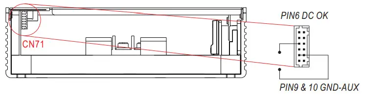
| DC-OK signal | Power Supply Status |
| “High” >4.4~5.5V | ON |
| “Low” <-0.5~0.5V | OFF |
5.PMBus Communication Interface
UHP-1500 supports PMBus Rev. 1.1 with maximum 100KHz bus speed, allowing information reading, status monitoring, output trimming, etc. For details, please refer to the Function Manual.
MECHANICAL SPECIFICATION
 : Max. Case Temperature
AC Input Terminal(TB1) Pin NO. Assignment
| Pin No. | Assignment | Terminal | Max mounting torque |
| 1 | AC/L | DECAT25 | 18Kgf-cm |
| 2 | AC/N | ||
| 3 |
DC Output Terminal(TB2,TB3) Pin NO. Assignment
| Pin No. | Assignment | Terminal | Max mounting torque |
| TB2 | +V | HS455A (MW) | 8Kgf-cm |
| TB3 | -V |
※DIP SW:
| Pin No. | Function | Description |
| 1 | AO | PMBus / CAN Bus interface address switch. |
| 2 | Al | |
| 3 | A2 |
※Control Pin No. Assignment(CN71) : HRS DF11-12DP-2DS or equivalent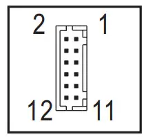
| Mating Housing | HRS DF11-12DS or equivalent |
| Terminal | HRS DF11-**SC or equivalent |
| Pin No. | Function | Description |
| 1 | PV | Connection for output voltage programming.(Note1) |
| 2 | PC | Connection for constant current level programming.(Note.1) |
| 3,4 | GND (Signal) | Negative output voltage signal. |
| 5 | Remote ON-OFF | The unit can turn the output ON/OFF by dry contact between Remote ON/OFF and 12-AUX.(Note.2) Short (10.8 —13.2V) : Power ON ; Open(0 — 0.5V) : Power OFF ; The maximum input voltage is 13.2V |
| 6 | DC-OK | Low (-0.5 — 0.5V) : When the Vout.S80%±6%. High (4.4 — 5.5V) : When Vout80%±6%. The maximum sourcing current is 10mA and only for output.(Note.2) |
| 7,8 | +12V-AUX | Auxiliary voltage output, 10.6-13.2V, referenced to GND-AUX (pin3 & 4). The maximum load current is 0.4A. This output is not controlled by “Remote ON-OFF”. |
| 9,10 | GND-AUX | Auxiliary voltage output GND. The signal return is isolated from the output terminals (+V & -V). |
| 11 | SDA | For PMBus model: Serial Data used in the PMBus interface. (Note.2) |
| CANH | For CANBus model: Data line used in CANBus interface. (Note.2) | |
| 12 | SCL | For PMBus model: Serial Clock used in the PMBus interface. (Note.2) |
| CANL | For CANBus model: Data line used in CANBus interface. (Note.2) |
Note1: Non-isolated signal, referenced to [GND(signal)].
Note2: Isolated signal, referenced to GND-AUX.
Operate with additional aluminum plate
In order to meet the “Derating Curve” and the “Static Characteristics” ,UHP-1500 series must be installed onto an aluminum plate(or the cabinet of the same size) on the bottom. The size of the suggested aluminum plate is shown as below. And for optimizing thermal performance, the aluminum plate must have an even and smooth surface (or coated with thermal grease), and UHP-1500 series must be firmly mounted at the center of the aluminum plate.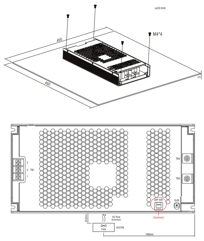
 |  |
| https://www.meanwell.com/webapp/product/search.aspx?prod=UHP-1500&pdf=VUhQLTE1MDAtRS5QREY=&a=4 | https://www.youtube.com/watch?v=0XCLiqb7le4&list=PLvUyt_OJELVrHoIIRgvHF2NQ-j39-NH-J&index=7 |
![]() File Name:UHP-1500-SPEC 2022-08-08
File Name:UHP-1500-SPEC 2022-08-08


