

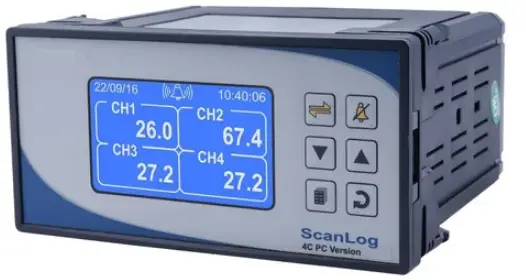
PPI ScanLog 4-8 Channel Recorder with Printer Interface
SPECIFICATIONS
| OPERATOR PARAMETERS | |
| Parameters | Settings (Default Value) |
| Stop Printing | No Yes |
| Select Option | 1. None 2. Print (New) 3. Re-print (Old) 4. Resume 5. Recover 6. Print Info Page (Default : None) |
| Batch Start Batch Stop | No Yes |
| Balance Slot Time | Read Only |
| Line Per Page | 25 to 100 (Default : 65) |
| Top Margine | 1 to 5 (Default : 2) |
| Bottom Margine | 1 to 5 (Default : 2) |
| Offset Records | 10 to 1000 (Default : 10) |
| Print Page Header>> | No On First Page Every Page (Default : Every Page) |
| Delete Page Header>> | No Yes |
| Delete Page Footer>> | No Yes |
| READ USB PARAMETERS | |
| Parameters | Settings (Default Value) |
| Select Option | 1. None 2. Read Set.txt File 3. Read Hdr.dat File 4. Read Ftr.dat File (Default : None) |
| ALARM SETTINGS | |
| Parameters | Settings (Default Value) |
| Select Channel | Channel-1 to Channel-4 (for 4C Printer Version) Channel-1 to Channel-8 (for 8C Printer Version) |
| Select Alarm | AL1, AL2, AL3, AL4 (The actual available options depends on the numbers of Alarms set per channel on Alarm configuration page) |
| AL1 Type | None Process Low Process High (Default : None) |
| AL1 Setpoint | Min. to Max. of selected input type range (Default : 0) |
| Parameters | Settings (Default Value) |
| AL1 Hysteresis | 1 to 30000 (Default : 20) |
| AL1 Inhibit | No Yes (Default : No) |
| DEVICE CONFIGURATION | |
| Parameters | Settings (Default Value) |
| Delete Records | No Yes (Default : No) |
| CHANNEL CONFIGURATION | |
| Parameters | Settings (Default Value) |
| All Chan Common | No Yes (Default : No) |
| Select Channel | Channel-1 to Channel-4 (for 4C Printer Version) Channel-1 to Channel-8 (for 8C Printer Version) |
| Input Type | Refer Table 1 (Default : 0 to 10 V) |
| Resolution | Refer Table 1 |
| Signal Low | |
| Signal High | |
| Parameters | Settings (Default Value) |
| Range Low | -30000 to +30000 (Default : 0) |
| Range High | -30000 to +30000 (Default : 1000) |
| Low Clipping | Disable Enable (Default : Disable) |
| Low Clip Val | -30000 to High Clip Val (Default : 0) |
| High Clipping | Disable Enable (Default : Disable) |
| High Clip Val | Low Clip Val to 30000 (Default : 1000) |
| Zero Offset | -30000 to +30000 (Default : 0) |
| ALARM CONFIGURATION | |
| Parameters | Settings (Default Value) |
| Alarms/Chan | 1 to 4 (Default : 4) |
| RECORDER CONFIGURATION | |
| Parameters | Settings (Default Value) |
| Normal Interval | 0:00:00 (H:MM:SS) to 2:30:00 (H:MM:SS) (Default : 0:00:30) |
| Zoom Interval | 0:00:00 (H:MM:SS) to 2:30:00 (H:MM:SS) (Default : 0:00:10) |
| Alrm Toggl Rec | Disable Enable (Default : Enable) |
| Recording Mode | Continuous Batch (Default : Continuous) |
| Batch Time | 0:01 (HH:MM) to 250:00 (HHH:MM) (Default : 1:00) |
| Batch Start Batch Stop | No Yes |
| RTC SETTING | |
| Parameters | Settings |
| Time (HH:MM) | 0.0 to 23:59 |
| Date | 1 to 31 |
| Month | 1 to 12 |
| Year | 2000 to 2099 |
| UTILITIES | |
| Parameters | Settings (Default Value) |
| Lock Unlock | No Yes (Default : No) |
| Factory Default | No Yes (Default : No) |
| TABLE 1 | ||
| Option | Range (Min. to Max.) | Resolution & Unit |
| Type J (Fe-K) | 0.0 to +960.0°C |
1 °C or 0.1 °C |
| Type K (Cr-Al) | -200.0 to +1376.0°C | |
| Type T (Cu-Con) | -200.0 to +387.0°C | |
| Type R (Rh-13%) | 0.0 to +1771.0°C | |
| Type S (Rh-10%) | 0.0 to +1768.0°C | |
| Type B | 0.0 to +1826.0°C | |
| Type N | 0.0 to +1314.0°C | |
| Reserved for customer specific Thermocouple type not listed above. The type shall be specified in accordance with the ordered (optional on request) Thermocouple type. | ||
| RTD Pt100 | -199.9 to +600.0°C | 1°C or 0.1 °C |
| 0 to 20 mA |
-30000 to 30000 units |
1 0.1 0.01 0.001 units |
| 4 to 20 mA | ||
| 0 to 80 mV | ||
| Reserved | ||
| 0 to 1.25 V |
-30000 to 30000 units | |
| 0 to 5 V | ||
| 0 to 10 V | ||
| 1 to 5 V | ||
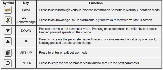
FRONT PANEL KEYS
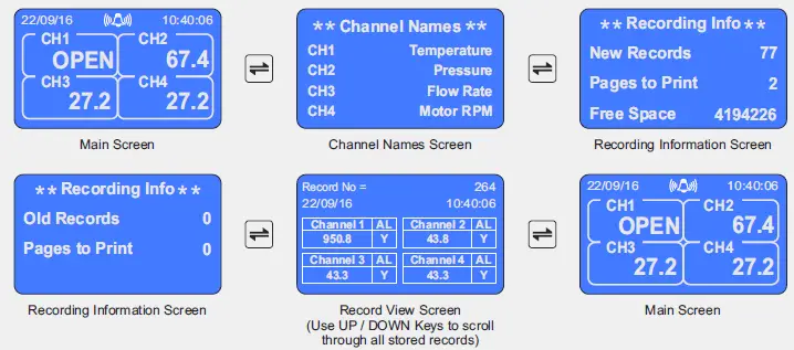
SCROLLING THROUGH VARIOUS SCREENS
The screen shown below are for 4 Channel Version. The sequence is the same for 8 Channel Version.
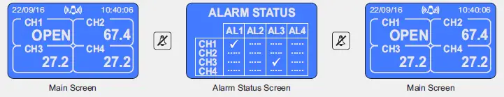
VIEWING ALARM STATUS SCREEN
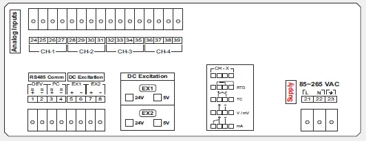
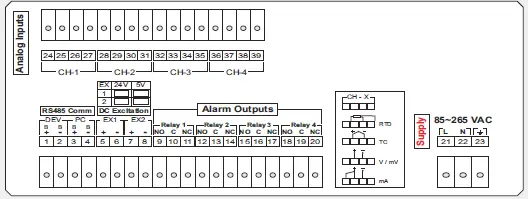
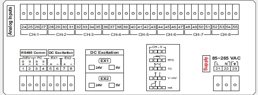
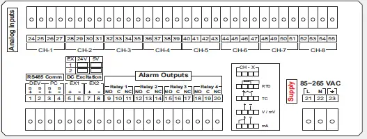
ELECTRICAL CONNECTIONS
4 Channel Without Alarm Relay Outputs
4 Channel With Alarm Relay Outputs
8 Channel Without Alarm Relay Outputs
8 Channel With Alarm Relay Outputs
This brief manual is primarily meant for quick reference to wiring connections and parameter searching. For more details on operation and application please log on to www.ppiindia.net
101, Diamond Industrial Estate, Navghar, Vasai Road (E), Dist. Palghar – 401 210.
- Sales : 8208199048 / 8208141446
- Support : 07498799226 / 08767395333
- E: [email protected], [email protected]


