![]()
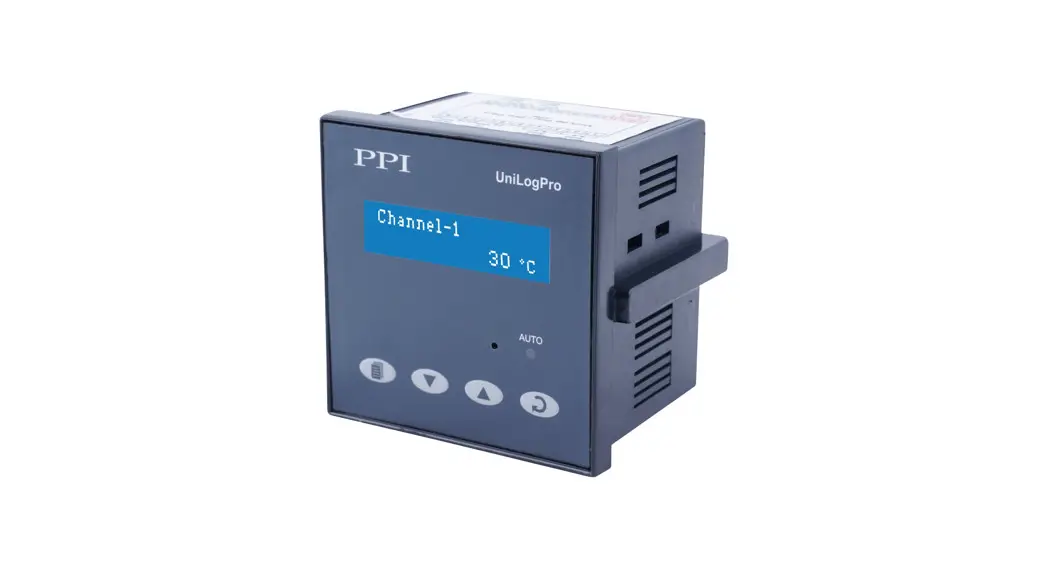
UniLog Pro / UniLog Pro Plus with CIM
Universal Process Data Recorder PC Software Version
UniLog Pro Temperature Data Logger
Operation Manual
This brief manual is primarily meant for quick reference to wiring connections and parameter searching. For more details on operation and application; please log on to www.ppiindia.net
| OPERATOR PARAMETERS | |
| Parameters | Settings (Default Value) |
| ‘Start’ Command for Batch Recording (Available if Batch Recording is selected) | No Yes |
| BATCH START>> NO | |
| ‘Stop’ Command for Batch Recording (Available if Batch Recording is selected) | No Yes |
| BATCH STOP>> NO | |
SUPERVISORY CONFIGURATION
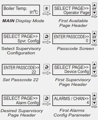
Note: AII the other Parameters are under SUPERVISORY CONFIGURATION
| ALARM SETTING | |
| Parameters | Settings (Default Value) |
| Channel Name for Alarm Settings SELECT CHANNEL>> Channel-1 | User defined or default names for channel-1 to channel-8 / 16 (Default : NA) |
| Select Alarm SELECT ALARM>> AL1 | AL1, AL2, AL3, AL4 (The actual available options depends on the numbers of Alarms set per channel on Alarm configuration page) |
| Alarm Type AL1 TYPE>> None | None Process Low Precess High (Default : None) |
| Alarm Setpoint AL1 SETPOINT>> 0 | Min. to Max. of selected input type range (Default : 0) |
| Alarm Hysteresis AL1 HYSTERESIS>> 2 | 1 to 3000 or 0.1 to 3000.0 (Default : 2 or 2.0) |
| Alarm Inhibit AL1 INHIBIT>> Yes | No Yes (Default : No) |
| DEVICE CONFIGURATION | |
| Parameters | Settings (Default Value) |
| Channel Update Time in Auto Scan Mode SCAN RATE>> 3 | 1 Sec. to 99 Sec. (Default : 3 Sec.) |
| Device Identification Number RECORDER ID>> 2 | 1 to127 (Default : 1) |
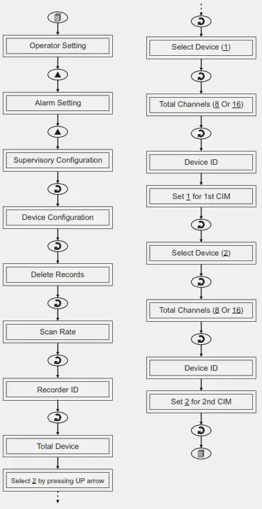
| Select Total Numbers of Channels TOTAL CHANNELS>> 16 | 8 16 (Default : 16) |
| Erase All Stored Records DELETE RECORDS>> No | No Yes (Default : No) |
| CHANNEL CONFIGURATION | |
| Parameters | Settings (Default Value) |
| Select Channel Name SELECT CHANNEL>> Channel-1 | User defined or default names for channel-1 to channel – 8 / 16 (Default : NA) |
| Skip Channel for Display SKIP>> No | No Yes (Default : Yes) |
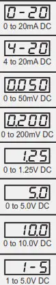
| Signal Input Type INPUT TYPE>> Type K (Cr-Al) | Refer Table 2 (Default : Type K (Cr-Al) |
| Display Resolution for Measured PV RESOLUTION>> 0.1 Unit | 1 Unit 0.1 Unit 0.01 Unit * 0.001 Unit * (Default : 0.1 Unit) (* for 4-20mA) |
| Display Units for Measured PV UNITS>> °C | Refer Table 1 (Default : °C) |
| Range Low (for 4-20mA) RANGE LOW>> 0 | -19999 to 30000 Counts with Selected Resolution (Default : 0.0) |
| Range High (for 4-20mA) RANGE HIGH>> 1000 | -19999 to 30000 Counts with Selected Resolution (Default : 100.0) |
| Apply Lower Clip on Displayed PV (for 4-20mA) LOW CLIPPING>> Disable | Disable Enable (Default : Disable) |
| Preset Lower Clip Level (for 4-20mA) LOW CLIP VAL>> 0.0 | -19999 to 30000 (Default : 0) |
| Apply Upper Clip on Displayed PV (for 4-20mA) HIGH CLIPPING>> Disable | Disable Enable (Default : Disable) |
| Preset Upper Clip Level (for 4-20mA) HIGH CLIP VAL>> 100.0 | -19999 to 30000 (Default : 100.0) |
| Zero Offset ZERO OFFSET>> 0 | -1999 / 3000 or -1999.9 / 3000.0 (Default : 0) |
| ALARM CONFIGURATION | |
| Parameters | Settings (Default Value) |
| Alarms Per Channel ALARMS / CHAN >> 4 | 1 to 4 (Default : 4) |
| Relay-1 Logic RELAY-1 LOGIC >> Normal | Normal Reverse (Default : Normal) |
| Relay-2 Logic RELAY-2 LOGIC >> Normal | Normal Reverse (Default : Normal) |
| RECORDER CONFIGURATION | |
| Parameters | Settings (Default Value) |
| Normal Recording Interval NORMAL INTERVAL>> 0:00:30 | 0:00:00 (H:MM:SS) to 2:30:00 (H:MM:SS) (Default : 0:00:30) |
| Zoom Recording Interval ZOOM INTERVAL>> 0:00:01 | 0:00:00 (H:MM:SS) to 2:30:00 (H:MM:SS) (Default : 0:00:01) |
| Record Generation on Alarm Status Toggle ALARM TOGGLE REC>> Disable | Disable Enable (Default : Enable) |
| Select Recording Mode RECORDING MODE>> Continuous | Continuous Batch (Default : Continuous) |
| Time Interval for Batch Recording (for Batch mode only) BATCH TIME>> 1.00 | 0:01 (HH:MM) to 250:00 (HHH:MM) (Default : 1:00) |
| RTC SETTING | |
| Parameters | Settings |
| Set Clock Time (HH:MM) TIME (HH:MM)>> 15:53 | 0.0 to 23:59 |
| Set Calendar Date DATE>> 23 | 1 to 31 |
| Set Calendar Month MONTH>> 11 | 1 to 12 |
| Set Calendar Year YEAR>> 2011 | 2000 to 2099 |
| UTILITIES | |
| Parameters | Settings |
| Master Lock Enable Disable LOCK>> No UNLOCK>> No |
No Yes |
| UIM Default UIM DEFAULT>> No | No Yes |
| CIM Default CIM DEFAULT>> No | No Yes |
| Make CIM & UIM Compatible CPY CIM TO UIM>> No CPY UIM TO CIM>> No | No Yes |
| TABLE- 1 | |
| Option | Description |
| °C | Degree Centigrade |
| °F | Degree Fahrenheit |
| (none) | No Unit (Blank) |
| °K | Degree Kelvin |
| EU | Engineering Units |
| % | Percentage |
| Pa | Pascals |
| Mpa | Mpascals |
| kPa | Kpascals |
| bar | Bar |
| mbar | Milli bar |
| psi | PSI |
| kg/sq.cm | kg/cm2 |
| mmH2O | mm water gauge |
| inH2O | Inches water gauge |
| mmHg | mm mercury |
| Torr | Torr |
| litre/hr | Litres per hour |
| litre/min | Litres per minute |
| %RH | % Relative Humidity |
| %O2 | % Oxygen |
| %CO2 | % Carbon di-oxide |
| %CP | % Carbon Potential |
| V | Volts |
| A | Amps |
| mA | Milli Amps |
| mV | Milli Volts |
| ohm | Ohms |
| ppm | Parts per million |
| rpm | Revolutions per minute |
| mSec | Milli seconds |
| Sec | Seconds |
| min | Minutes |
| hrs | Hours |
| PH | PH |
| %PH | %PH |
| miles/hr | Miles per hour |
| mg | Milli grams |
| g | Grams |
| kg | Kilo grams |
| TABLE- 2 | ||
| Option | Range (Min. to Max.) | Resolution |
| 0 to +960°C / +32 to +1760°F |
Fixed 1°C / 1°F | |
| 0 to +1771°C / +32.0 to +3219°F | |
| 0 to +1768°C / +32 to +3214°F | ||
| Reserved for customer specific Thermocouple type not listed above. | ||
| -199 to +600°C / -328 to +1112°F –199.9 to or to 1112.0°F 600.0°C / -328.0 | User settable 1°C / 1°F or 0.1°C / 0.1°F | |
|
| 19999 to +30000 units | User settable 1 / 0.1 / 0.01/ 0.001 unts |
ID SETTING FOR MORE THAN 1 CIM
Applicable only for UNILOG PRO PLUS
FRONT PANEL LAYOUT
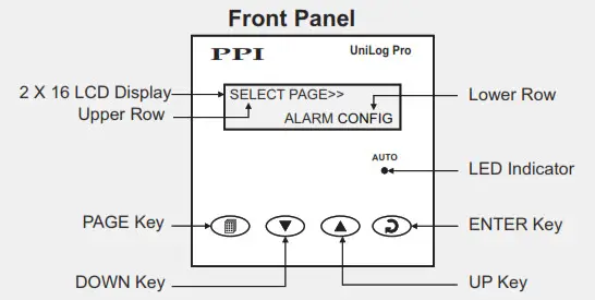
Symbol | Key | Function |
| PAGE | Press to enter or exit set-up mode. | |
| DOWN | Press to decrease the parameter value. Pressing once decreases the value by one count; holding pressed speeds up the change. | |
| UP | Press to increase the parameter value. Pressing once increases the value by one count; holding pressed speeds up the change. | |
| ENTER | Press to store the set parameter value and to scroll to the next parameter on the PAGE. |
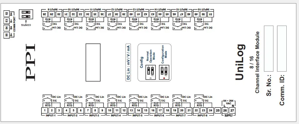
ELECTRICAL CONNECTIONS
USER INTERFACE MODULE (UIM)
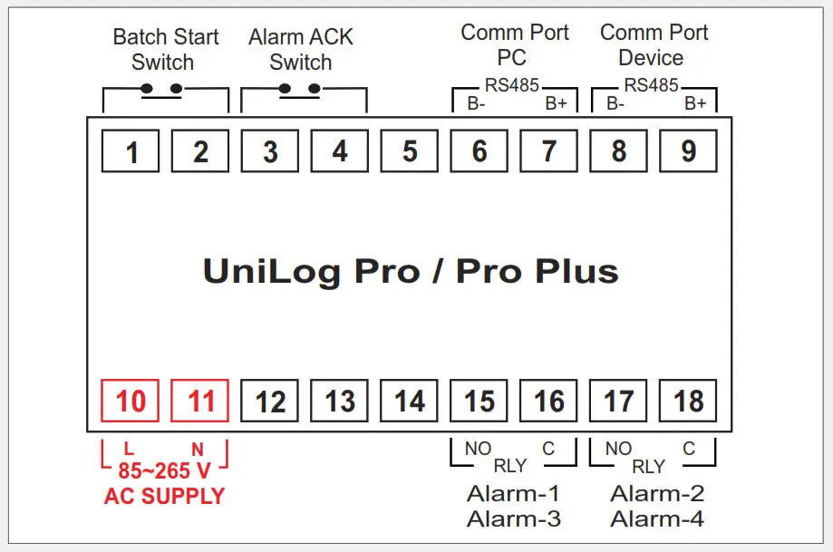
COMMUNICATION PORT FOR INTERFACING WITH CIM(S)
Applicable only for UNILOG PLUS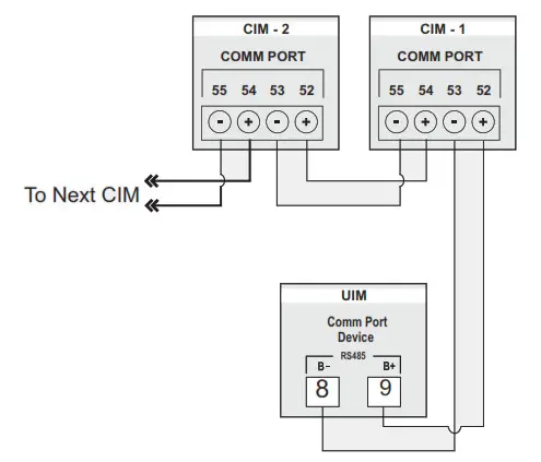
JUMPER SETTINGS
INPUT-CHANNEL INTERFACE MODULE (CIM)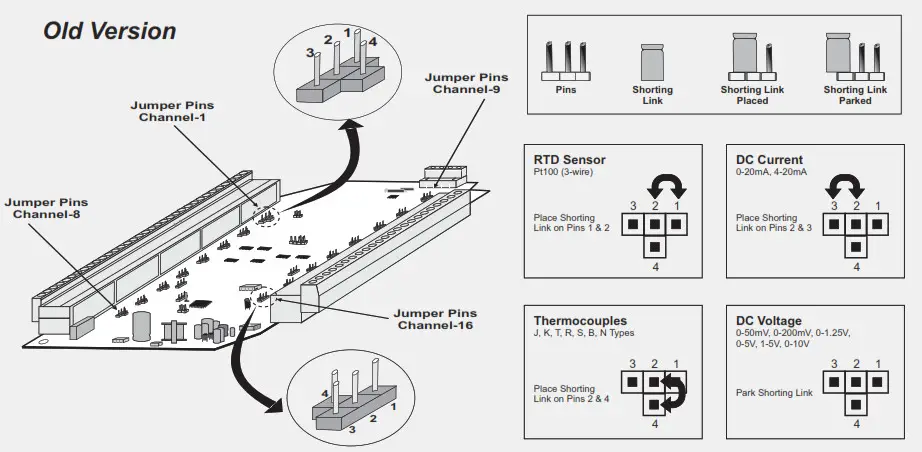
JUMPER SETTINGS
INPUT-CHANNEL INTERFACE MODULE (CIM)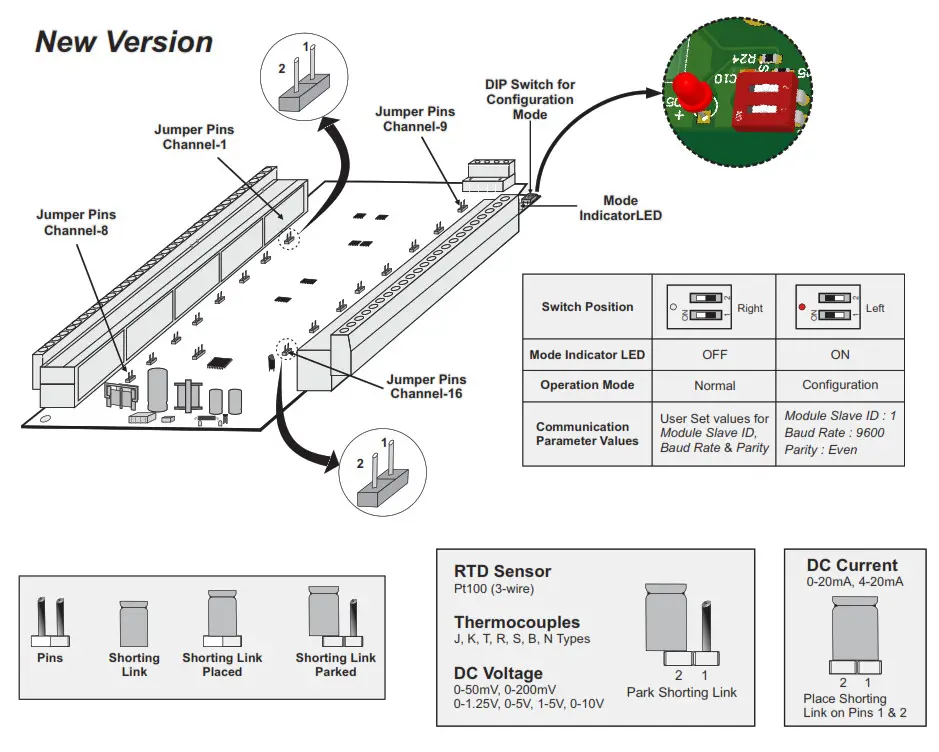
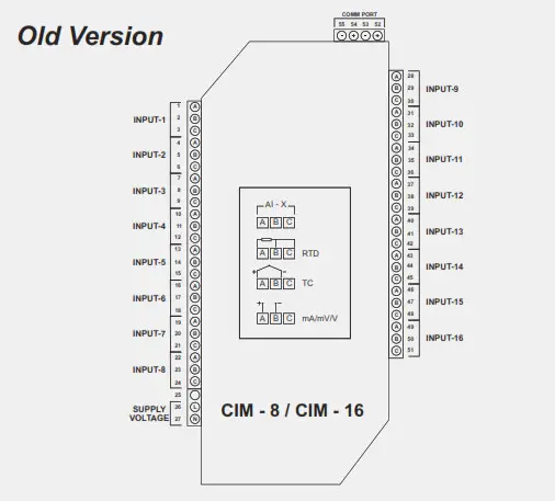
ELECTRICAL CONNECTIONS
CHANNEL INTERFACE MODULE (CIM)