![]()
CIM Plus – 8 / 16
8/16 Universal Channel
Analog Interface Module (AC Powered)
Operation Manual
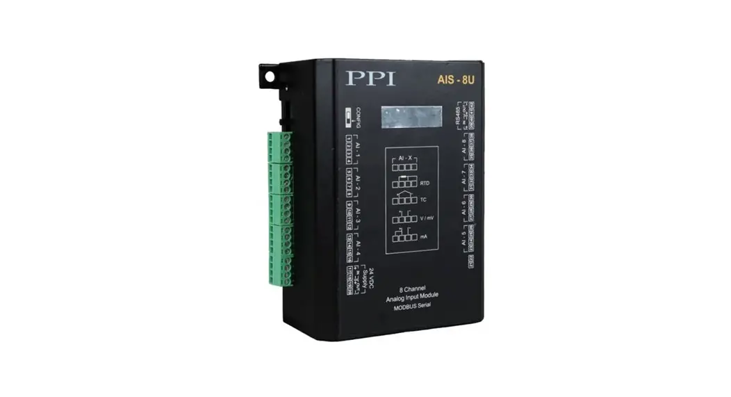
CIM Plus – 8 / 16 Universal Channel Analog Interface Module
This brief manual is primarily meant for quick reference to wiring connections and parameter searching. For more details on Zoperation and application; please log on to www.ppiindia.net
| Input Registers (Read-Only Parameters) | ||||||||||
| Parameter | MODBUS Address | Values | ||||||||
| Process Value | 1561 to 1568 0(8 Channels) 1561 to 1576 (16 Channels) |
| ||||||||
| Alarm-1 Status | 1577 | 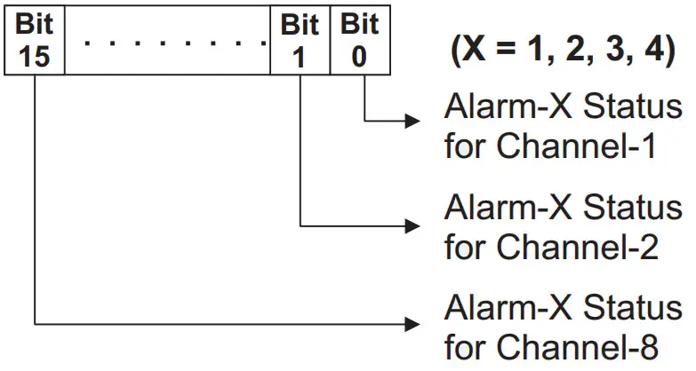
For 8 Channel Version (CIM Plus-8), ignore Bit-8 to Bit-15 | ||||||||
| Alarm-2 Status | 1578 | |||||||||
| Alarm-3 Status | 1579 | |||||||||
| Alarm-4 Status | 1580 | |||||||||
| Ambient Temperature | 82 | Signed integer values from -30000 to +30000 representing the measured Ambient Temperature through the semi-conductor sensor mounted on the Module. The measured value is always in °C with 0.1 resolution. For example, 30.0°C is represented as 300. | ||||||||
| Holding Registers (Read / Write Parameters) | ||||||||||||||||||||||||||||||||||||||
| Parameter | MODBUS Address | Settings (Default Value) | ||||||||||||||||||||||||||||||||||||
| Input Type | 83 to 90 (8 Channels) 83 to 98 (16 Channels) |
(Default : 0 to 10 V) | ||||||||||||||||||||||||||||||||||||
| Temperature Units | 99 to 106 (8 Channels) 99 to 114 (16 Channels) |
Conditional Parameter ”””” | ||||||||||||||||||||||||||||||||||||
| DC Resolution ””’ | 115 to 122 (8 Channels) 115 to 130 (16 Channels) |
Conditional Parameter ‘ | ||||||||||||||||||||||||||||||||||||
| Parameter | MODBUS Address | Settings (Default Value) | ||||||||||||||||||||||||
| Signal Low | 501 to 508 (8 Channels) 501 to 516 (16 Channels) | Conditional Parameter
| ||||||||||||||||||||||||
| Signal High | 517 to 524 (8 Channels) 517 to 532 (16 Channels) | Conditional Parameter ‘
| ||||||||||||||||||||||||
| Range Low | 131 to 138 (8 Channels) 131 to 146 (16 Channels) | Conditional Parameter -30000 to 30000 (Default : 0) | ||||||||||||||||||||||||
| Range High | 147 to 154 (8 Channels) 147 to 162 (16 Channels) | Conditional Parameter -30000 to 30000 (Default : 1000) | ||||||||||||||||||||||||
| Offset for PV ”'” fl | 163 to 170 (8 Channels) 163 to 178 (16 Channels) | -30000 to 30000 (Default : 0) | ||||||||||||||||||||||||
| Alarm-1 Type | 179 to 186 (8 Channels) 179 to 194 (16 Channels) |
(Default : None) | ||||||||||||||||||||||||
| Alarm-2 Type | 243 to 250 (8 Channels) 243 to 258 (16 Channels) | |||||||||||||||||||||||||
| Alarm-3 Type | 307 to 314 (8 Channels) 307 to 322 (16 Channels) | |||||||||||||||||||||||||
| Alarm-4 Type | 371 to 378 (8 Channels) 371 to 386 (16 Channels) | |||||||||||||||||||||||||
| Alarm-1 Set-point ‘ TI | 195 to 202 (8 Channels) 195 to 210 (16 Channels) | Min. to Max. Range specified for the selected Input Type Refer Table 1 (Default : Min or Max Range depending on the Alarm type) | ||||||||||||||||||||||||
| Alarm-2 Set-point ‘”” n | 259 to 266 (8 Channels) 259 to 274 (16 Channels) | |||||||||||||||||||||||||
| Alarm-3 Set-point ””’I | 323 to 330 (8 Channels) 323 to 338 (16 Channels) | |||||||||||||||||||||||||
| Alarm-4 Set-point'””‘ ‘I | 387 to 394 (8 Channels) 387 to 402 (16 Channels) |
| Parameter | MODBUS Address | Settings (Default Value) | ||||||
| Alarm-1 Hysteresis ”””” | 211 to 218 (8 Channels) 211 to 226 (16 Channels) | 1 to 30000 (Default : 20) | ||||||
| Alarm-2 Hysteresis ‘by’. “ | 275 to 282 (8 Channels) 275 to 290 (16 Channels) | |||||||
| Alarm-3 Hysteresis ‘ 1 | 339 to 346 (8 Channels) 339 to 354 (16 Channels) | |||||||
| Alarm-4 Hysteresis ”” “ | 403 to 410 (8 Channels) 403 to 418 (16 Channels) | |||||||
| Alarm-1 Inhibit | 227 to 234 (8 Channels) 227 to 242 (16 Channels) |
(Default : Disable) | ||||||
| Alarm-2 Inhibit | 291 to 298 (8 Channels) 291 to 306 (16 Channels) | |||||||
| Alarm-3 Inhibit | 355 to 362 (8 Channels) 355 to 370 (16 Channels) | |||||||
| Alarm-4 Inhibit | 419 to 426 (8 Channels) 419 to 434 (16 Channels) | |||||||
| Enable Bottom Clipping | 435 to 442 (8 Channels) 435 to 450 (16 Channels) |
(Default : No) | ||||||
| Bottom Clip Value | 451 to 458 (8 Channels) 451 to 466 (16 Channels) | -30000 to 30000 (Default : 0) | ||||||
| Enable Top Clipping | 467 to 474 (8 Channels) 467 to 482 (16 Channels) |
(Default : No) | ||||||
| Top Clip Value | 483 to 490 (8 Channels) 483 to 498 (16 Channels) | -30000 to 30000 (Default : 1000) |
| CONFIGURING COMMUNICATION PARAMETERS | ||||||||||||||||||
| Parameter | MODBUS Address | Settings (Default Value) | ||||||||||||||||
| Modbus Slave ID | 1 | 1 to 247 (Default : 1) | ||||||||||||||||
| Baud Rate | 2 |
(Default : 9600 bps) | ||||||||||||||||
| Parity | 3 |
(Default : Even) | ||||||||||||||||
Note 1
Thermocouples (J, K, T, R, S, B, N) and RTD Pt100 (3-wire) Inputs
The process value is always measured in 0.1°C/°F resolution. That is, for example, the value 300 means 30.0°C / °F.
The same should be followed while setting the values for the parameters that are resolution based (like Zero Offset, Alarm Set-point, Alarm Hysteresis, etc.). That is for example, set 300 counts for 30.0°C / °F. DC mA / mV / V Inputs
(Also Refer Appendix A : DC Linear Signal Interface)
The measured PV is a Resolution-less Scaled Value derived using the values for the parameters : Signal Low, Signal High, Range Low and Range High. The parameter ‘DC Resolution’ holds the desired resolution that can be used to insert appropriate Decimal Place in the scaled PV. For example, if the DC Resolution value is 2 (0.01) then the scaled value of 3000 can be read as 30.00.
Similarly the corresponding parameters like Zero Offset, Alarm Set-point, Alarm Hysteresis, etc., are also resolution less and, if desired, the parameter value for ‘DC Resolution’ should be used for appropriate Decimal Place.
Note 2
Conditional Parameters are those whose usage depend upon the values set for some other parameters. For example; the parameters ‘Signal Low’ & ‘Signal High’ for a selected channel are used only if the input type for the selected channel is DC Input (mV / V / mA). The access to the conditional parameters for Read / Write operation, however, is not restricted.
Table 1 | ||
| Input Type | Range (Min. to Max.) | Resolution |
| Type J Thermocouple | 0 to +960.0°C / +32.0 to +1760.0°F | 0.1 °C / °F |
| Type K Thermocouple | -200.0 to +1376.0°C / -328.0 to +2508.0°F | |
| Type T Thermocouple | -200.0 to +387.0°C / -328.0 to +728.0°F | |
| Type R Thermocouple | 0 to +1771.0°C / +32.0 to +3219.0°F | |
| Type S Thermocouple | 0 to +1768.0°C / +32.0 to +3214.0°F | |
| Type B Thermocouple | 0 to +1826.0°C / +32.0 to +3218.0°F | |
| Type N Thermocouple | 0 to +1314.0°C / +32.0 to +2397.0°F | |
| 3-wire, RTD Pt100 | -199.0 to +600.0°C / -328.0 to +1112.0°F | |
| 0 to 20mA DC current | -30000 to 30000 units | 1 |
| 4 to 20mA DC current | ||
| 0 to 80mV DC voltage | ||
| 0 to 1.25V DC voltage | ||
| 0 to 5.0V DC voltage | ||
| 0 to 10.0V DC voltage | ||
| 1 to 5.0V DC voltage | ||
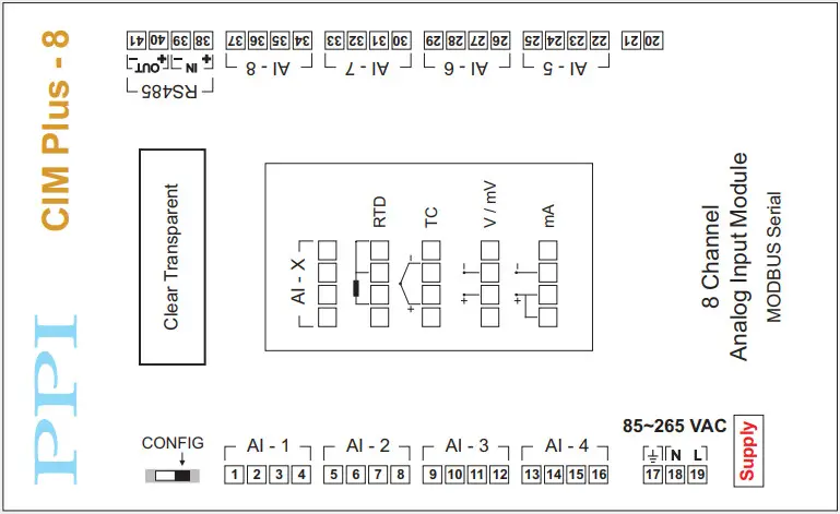
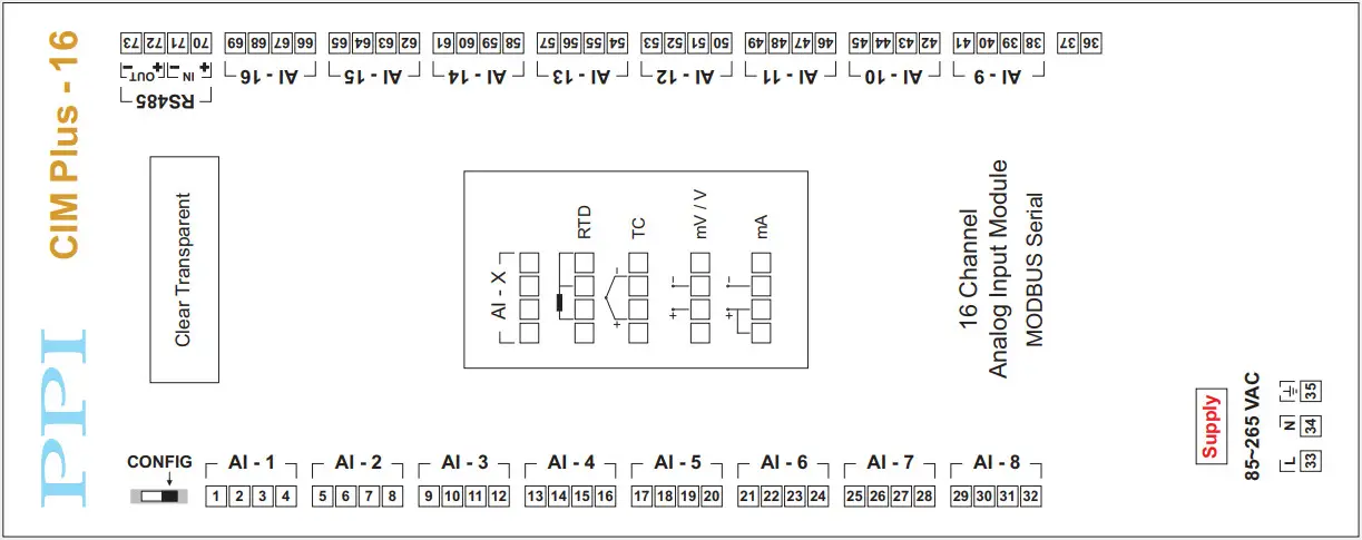
ELECTRICAL CONNECTIONS
CONFIGURING COMMUNICATION
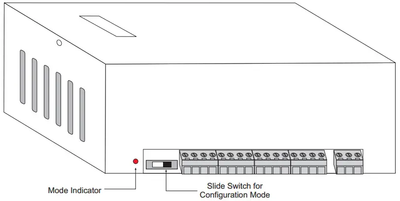
| Slide Switch Position |
|
|
| Mode Indicator | OFF | ON |
| Operation Mode | Normal | Configuration |
| Communication Parameter Values | User Set values for Module Slave ID, Baud Rate & Parity | Module Slave ID : 1 Baud Rate : 9600 Parity : Even |
![]() 101, Diamond Industrial Estate, Navghar,
101, Diamond Industrial Estate, Navghar,
Vasai Road (E), Dist. Palghar – 401 210.
Sales : 8208199048 / 8208141446
Support : 07498799226 / 08767395333
[email protected]
E: [email protected]


