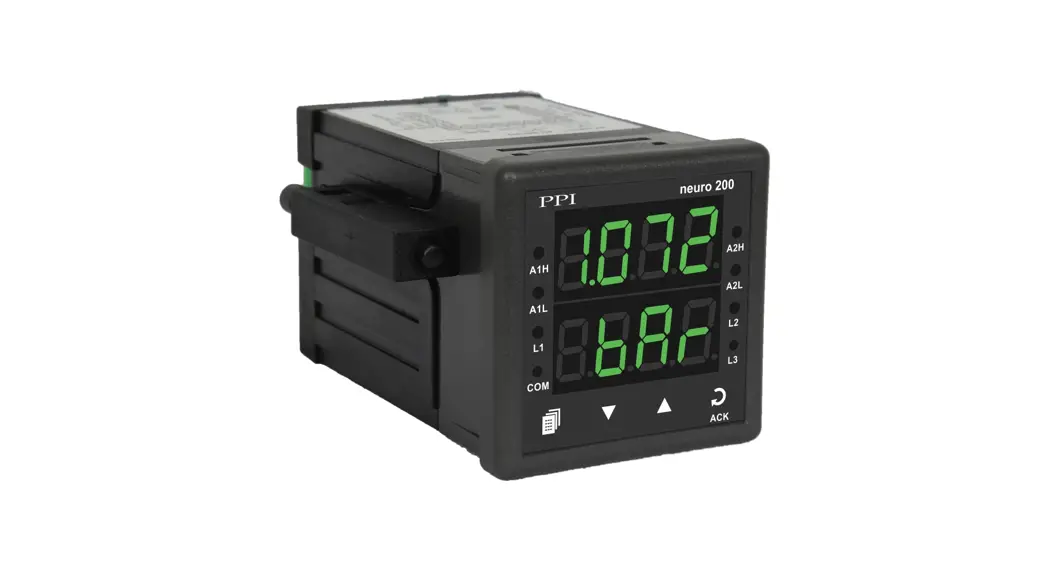
![]() Neuro 200 Advanced Universal Process Indicator
Neuro 200 Advanced Universal Process Indicator
Instruction Manual
This brief manual is primarily meant for quick reference to wiring connections and parameter searching. For more details on operation and application; please log on to www.ppiindia.net
OPERATOR PAGE AND PARAMETERS
| Parameters | Settings (Default Value) |
| Alarm Acknowledge | (Default : No) |
| Maximum PV | View Only (Default : NA) |
| Minimum PV | View Only (Default : NA) |
| Reset Command | (Default : No) |
| Reset Password | 0 to 250 (Default : 0) |
| Alarm-1 Setpoint | Min to max Range specified for the selected Input Type (Default: Min or Max Range) |
| Alarm-2 Setpoint | Min to max Range specified for the selected Input Type (Default : Min or Max Range) |
ALARM PARAMETERS
| Parameters | Settings (Default Value) |
| Alarm-1 Type | (Default : None) |
| Alarm-1 Setpoint | Min to max Range specified for the selected Input Type (Default : Min or Max Range) |
| Alarm-1 Hysteresis | 1 to 999 or 0.1 to 999.9 (Default : 2.0) |
| Alarm-1 Inhibit | (Default : Yes) |
| Alarm-1 Logic | (Default : Normal) |
| Alarm Latch | (Default : No) |
| Alarm-2 Type | (Default : None) |
| Alarm-2 Setpoint | Min to max Range specified for the selected Input Type (Default : Min or Max Range) |
| Alarm-2 Hysteresis | 1 to 999 or 0.1 to 999.9 (Default : 2.0) |
| Alarm-2 Inhibit | (Default : Yes) |
| Alarm-2 Logic | (Default : Normal) |
| Alarm Latch | (Default : No) |
RE TRANSMISSION PARAMETERS
| Parameters | Settings (Default Value) |
| Recorder Output Type | (Default : 0 to 20mA) |
| Recorder Low | Min. to Max. Range specified for the selected Input Type (Default : -200) |
| Recorder High | Min. to Max. Range specified for the selected Input Type (Default : 1376) |
INPUT CONFIGURATION PARAMETERS
| Parameters | Settings (Default Value) | |||||||||||||||||||||||||||
| Input Type | Refer Table 2 (Default : Type K) | |||||||||||||||||||||||||||
| Units | Refer Table 1 (Default : ºC) | |||||||||||||||||||||||||||
| Signal Range Low |
| |||||||||||||||||||||||||||
| Signal Range High |
| |||||||||||||||||||||||||||
| Resolution | Refer Table 2 (Default : 1) | |||||||||||||||||||||||||||
| DC Range Low | -1999 to 9999 (Default : 0.0) | |||||||||||||||||||||||||||
| DC Range High | -1999 to 9999 (Default : 100.0) | |||||||||||||||||||||||||||
| Offset | -1999 to 9999 or -199.9 to 999.9 (Default : 0) | |||||||||||||||||||||||||||
| Filter | 0.5 to 60.0 Seconds (in steps of 0.5 Seconds) (Default : 2.0 sec.) |
SUPERVISORY PARAMETERS
| Parameters | Settings (Default Value) |
| Alarm SP Adjustment on Operator Page | (Default : Disable) |
| Process Value High-Low Monitoring | (Default : No) |
| Password for Resetting PV High-Low | 0 to 250 (Default : 0) |
| Serial ID Number | 1 to 127 (Default : 1) |
| Baud Rate | (Default : 9.6) |
| Parity | (Default : Even) |
| Serial Write Permission | (Default : Yes) |
USER LINEARISATION PARAMETERS
| Parameters | Settings (Default Value) |
| User Linearization Setting Code | 0 to 9999 (Default : 0) |
| User Linearization | (Default : No) |
| Total Break Points | 2 to 32 (Default : 2) |
| Break Point Number | 1 to 32 (Default : 1) |
| Actual Value for Break Point (X co-ord) | -1999 to 9999 (Default : Undefined) |
| Derived Value for Break Point (Y co-ord) | -1999 to 9999 (Default : Undefined) |
TABLE- 1
| Lower Readout | Units | |
| °C | Temperature | |
| °F | ||
| Kelvin | ||
| Engineering Units | ||
| Percentage | ||
| Pascals | Pressure | |
| Mpascals | ||
| Kpascals | ||
| Bar | ||
| Milli bar | ||
| PSI | ||
| kg/sq cm | ||
| mm water gauge | Pressure | |
| Inches water gauge | ||
| mm mercury | ||
| Torr | ||
| Litres per hour | Flow | |
| Litres per minute | ||
| % Relative Humidity | ||
| % O2 | ||
| % CO2 | ||
| % Carbon Potential | ||
| volts | Electricity | |
| Amps | ||
| Milli amps | ||
| Milli Volts | ||
| Ohms | ||
| Parts per million | ||
| Revolutions per pinute | ||
| Milli seconds | Time | |
| Seconds | ||
| Minutes | ||
| Hours | ||
| PH | ||
| %PH | ||
| Miles per hour | ||
| Milli grams | Weight | |
| Grams | ||
| Kilo grams |
| Lower Readout | Units | |
| mm (Millimeter) | Length/Height/Distance | |
| cm (Centimeter) | ||
| Meter | ||
| Kilometre | ||
| Foot | ||
| Inch | ||
| Mile |
Table 2
| Option | What it means | Range (Min. to Max.) | Resolution |
| Type J Thermocouple | 0 to +960°C / +32 to +1760°F | Fixed 1°C/1°F | |
| Type K Thermocouple | -200 to +1376°C / -328 to +2508°F | ||
| Type T Thermocouple | -200 to +385°C / -328 to +725°F | ||
| Type R Thermocouple | 0 to +1770°C / +32 to +3218°F | ||
| Type S Thermocouple | 0 to +1765°C / +32 to +3209°F | ||
| Type B Thermocouple | 0 to +1825°C / +32 to +3092°F | ||
| Type N Thermocouple | 0 to +1300°C / +32 to +2372°F | ||
| Reserved for customer specific Thermocouple type not listed above. The type shall be specified in accordance with the ordered (optional on request) Thermocouple type. | |||
| 3-wire, RTD Pt100 | -199 to +600°C/-328 to +1112°F or -199.9 to 600.0°C/-199.9 to 999.9°F | User settable 1°C/1°F or 0.1°C/0.1°F | |
| 0 to 20mA DC current | -1999 to +9999 units | User settable 1 / 0.1 / 0.01/ 0.001 units | |
| 4 to 20mA DC current | |||
| Reserved | |||
| 0 to 80 mV DC voltage | |||
| 0 to 1.25V DC voltage | |||
| 0 to 5.0V DC voltage | |||
| 0 to 10.0V DC voltage | |||
| 1 to 5.0V DC voltage | |||
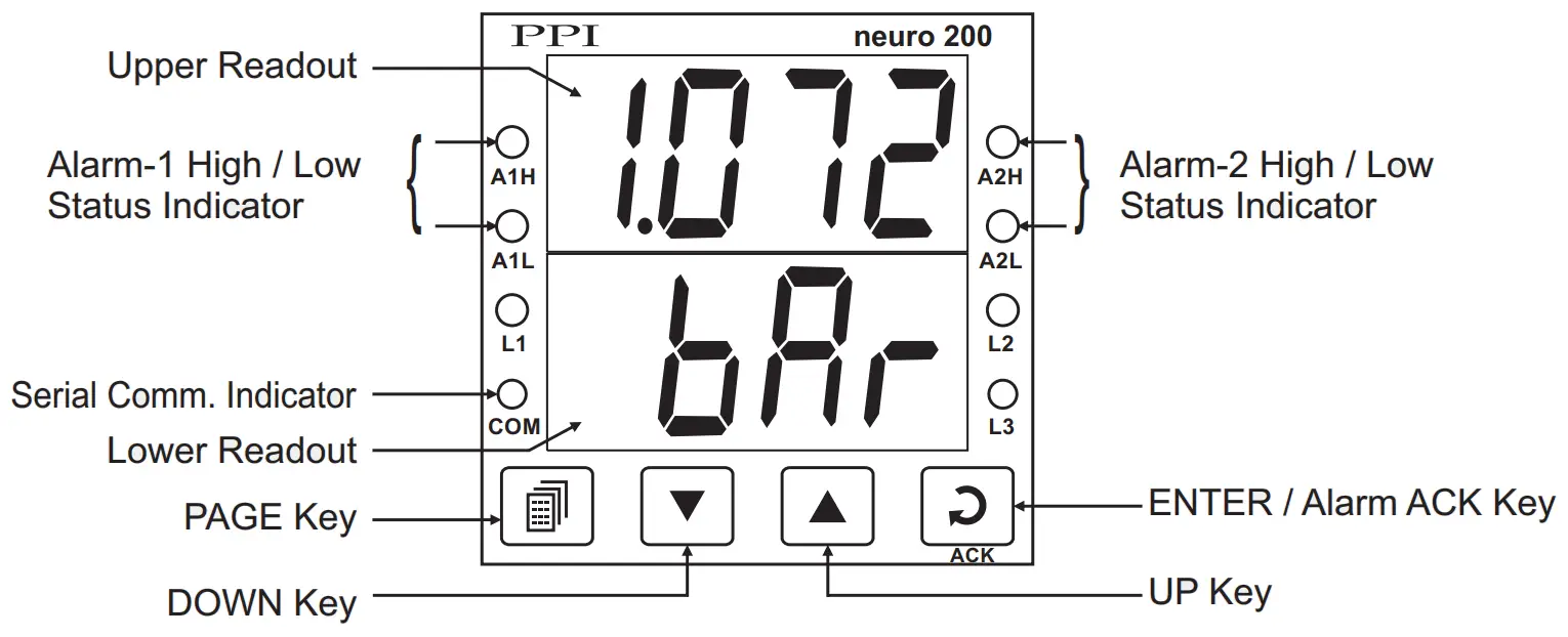
FRONT PANEL LAYOUT
Keys Operation
| Symbol | Key | Function |
| PAGE | Press to enter or exit set-up mode. | |
| DOWN | Press to decrease the parameter value. Pressing once decreases the value by one count; keeping pressed speeds up the change. | |
| UP | Press to increase the parameter value. Pressing once increases the value by one count; keeping pressed speeds up the change. | |
| ENTER/ACK | Set up Mode: Press to store the set parameter value and to scroll to the next parameter on the PAGE. Run Mode: Press to acknowledge any pending Alarm(s). This also turns off the Alarm relay. |
PV Error Indications
| Message | PV Error Type |
| Over-range (PV above Max. Range) | |
| Under-range (PV below Min. Range) | |
| Open (Sensor open/broken) |
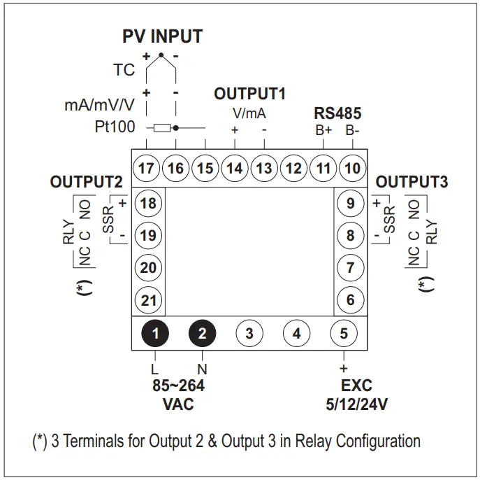
ELECTRICAL CONNECTIONS
![]() 101, Diamond Industrial Estate, Navghar,
101, Diamond Industrial Estate, Navghar,
Vasai Road (E), Dist. Palghar – 401 210.
Sales: 8208199048/8208141446
Support: 07498799226/08767395333
E: [email protected]
[email protected]
Dec 2021


