![]() Neuro 104
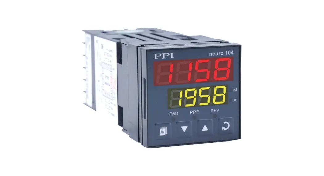
Neuro 104
Motorized Valve Controller
User Manual
Neuro 104 Motorized Valve Controller
This brief manual is primarily meant for quick reference to wiring connections and parameter searching. For more details on operation and application; please log on to www.ppiindia.net
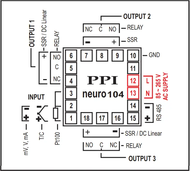
ELECTRICAL CONNECTIONS
 ENCLOSURE ASSEMBLY
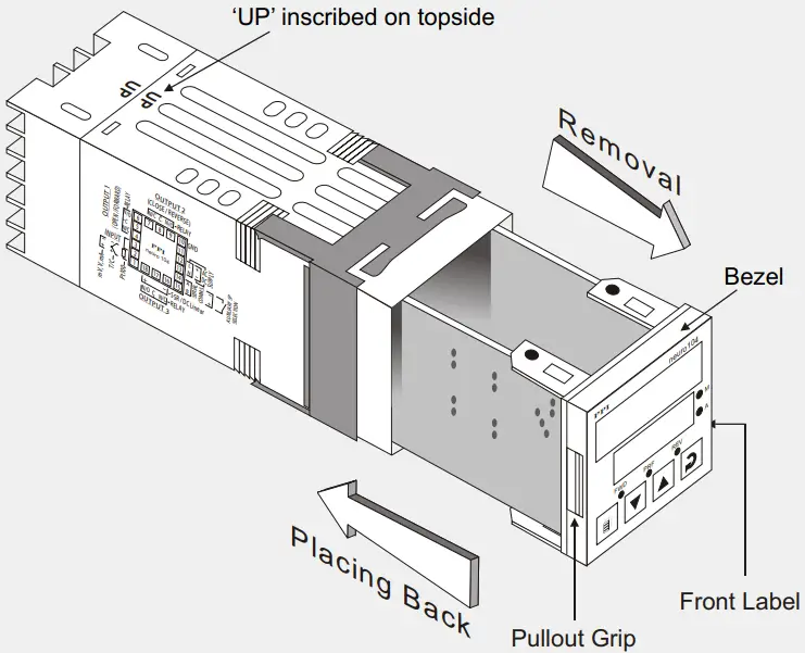
MOUNTING DETAILS
OUTPUT-3 MODULE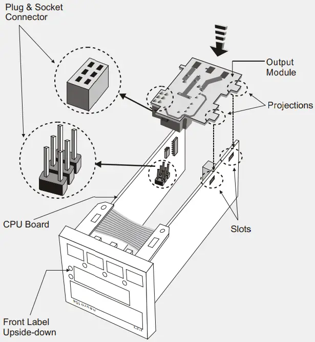
JUMPER SETTINGS
OUTPUT-3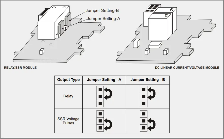 MOUNTING DETAILS
SERIAL COMM. MODULE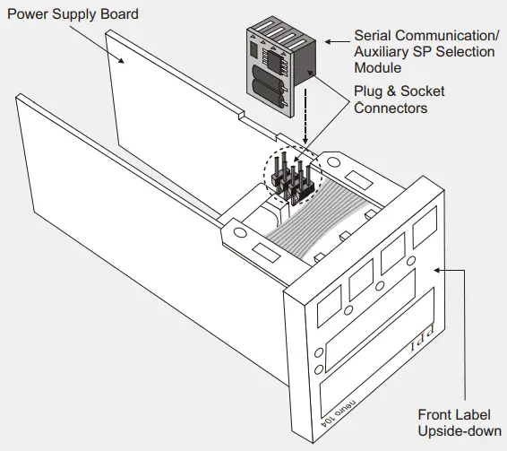 CONFIGURATION PARAMETERS
| Parameters | Settings (Default Value) |
| Control Logic | Direct (Default : Reverse) |
| Input Type | Refer Table 1 (Default : Type K) |
| PV Units | |
| PV Resolution | Refer Tablet (Default : 1) |
| PV Range Low | Refer Table1 (Default : 0) |
| PV Range High | Refer Tablet (Default : 1000) |
| Setpoint Low Limit | Min. Range for the selected Input Type to Setpoint High Limit (Default : -200) |
| Setpoint High Limit | Setpoint Low Limit to Max. Range for the selected Input Type (Default : 1300) |
| Offset for PV | -1999 to 9999 (Default : 0) |
| Digital Filter for PV | 0.5 to 25.0 Seconds (in steps of 0.5 Seconds) (Default : 1.0 Sec.) |
| Sensor Break (Open) Strategy | Close Open (Default : Close) |
CONTROL PARAMETERS
| Parameters | Settings (Default Value) |
| Proportional Band | 1 to 999 Units (Default : 50 units) |
| Integral Time | 0 to 1000 Seconds (Default : 100 Sec.) |
| Derivative Time | 0 to 250 Seconds (Default : 25 Sec.) |
| Motor Run Time (Travel Time) | Minimum ON Time to 240.0 (Default : 30.0) |
| Valve Inertia Time | 0.0 to 20.0 (Default : 0.0) |
| Valve Backlash Time | 0.0 to 20.0 (Default : 0.0) |
| Minimum ON Time | 0.3 to Motor Run Time (Default : 1.0) |
SUPERVISORY PARAMETERS
| Parameters | Settings (Default Value) |
| Self-Tune Command | |
| Overshoot Inhibit | |
| Overshoot Inhibit Factor | 1.0 to 2.0 (Default: 1.0) |
| Set-up Made (SP Adjustment on Lower Readout) | |
| SP Adjustment on Operator Page | |
| Manual Mode | |
| Alarm SP Adjustment on Operator Page | |
| Standby Mode | |
| Profile Abort Command on Operator Page | |
| Auxiliary Setpoint or Serial Comm. Option Selection | Serial Comm Auxiliary Setpoint (Default: None) |
| Baud Rate | 1200, 2400, 4800, 9600 (Default: 9600) |
| Controller ID Number | 1 to 127 (Default: 1) |
| Communication Write Enable |
OP3 FUNCTION PARAMETERS
| Parameters | Settings (Default Value) |
| Output-3 Function Selection | |
| Recorder Output Transmission | |
| Recorder Output Type | |
| Min. to Max. Range Specified for the Selected Input Type (Default: -200) | |
| Min. to Max. Range Specified for the Selected Input Type (Default: 1300) |
ALARM PARAMETERS
| Parameters | Settings (Default Value) |
| Alarm Type | |
| Alarm Setpoint | Min. to Max. Range Specified for the Selected Input Type (Default : For Process Low : -200 & Process High : 1300) |
| Alarm Deviation | -999 to 999 (Default : )3 |
| Alarm Band | 3 to 999 (Default : )3 |
| Alarm Hysteresis | 1 to 999 (Default : )2 |
| Alarm Logic | |
| Alarm Inhibit |
PROFILE PARAMETERS
| Parameters | Settings (Default Value) |
| Profile mode selection | |
| Ramp Hold Band | 0 to 250 (Default : 0) |
| Soak Hold Band | 0 to 250 (Default : 0) |
| Ramp Rate-1 | 0.00 to 99.99 (Default : 0.00) |
| Target Setpoint-1 | Min. to Max. Range Specified for the Selected Input Type (Default : -200) |
| Soak Time-1 | 0 to 9999 (Default : 0) |
| Ramp Rate-2 | 0.00 to 99.99 (Default : 0.00) |
| Target Setpoint-2 | Min. to Max. Range Specified for the Selected Input Type (Default : -200) |
| Soak Time-2 | 0 to 9999 (Default : 0) |
| Ramp Rate-3 | 0.00 to 99.99 (Default : 0.00) |
| Target Setpoint-3 | Min. to Max. Range Specified for the Selected Input Type (Default : -200) |
| Soak Time-3 | 0 to 9999 (Default : 0) |
| Ramp Rate-4 | 0.00 to 99.99 (Default : 0.00) |
| Target Setpoint-4 | Min. to Max. Range Specified for the Selected Input Type (Default : -200) |
| Soak Time-4 | 0 to 9999 (Default : 0) |
| Output Off |
OPERATOR PARAMETERS
| Parameters | Settings (Default Value) |
| Stand By Mode |  (Default : No) |
| Profile Start Command | (Default : No) |
| Profile Abort Command | (Default : No) |
| Control Setpoint | Setpoint Low to Setpoint High (Default : -200) |
| Auxiliary Setpoint | Setpoint Low to Setpoint High (Default : -200) |
| Alarm Setpoint | Min. to Max. Range Specified for the Selected Input Type (Default : For Process Low : -200 & Process High : 1300) |
| Alarm Deviation | -999 to 999 (Default : 3) |
| Alarm Band | 3 to 999 (Default : 3) |
TABLE- 1
| Option | Range (Min. to Max.) | Resolution |
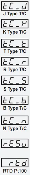 | 0 to +760°C / +32 to +1400°F | |
| -200 to +1300°C / -328 to +2372°F | ||
| -200 to +350°C / -328 to +662°F | ||
| 0 to +1770°C / +32 to +3092°F | ||
| 0 to +1700°C / +32 to +3092°F | ||
| +200 to +1700°C / +392 to +3092°F | ||
| 0 to +1300°C / +32 to +2372°F | ||
| Reserved for customer specific Thermocouple type not listed above. | ||
| -199 to +600°C / -328 to +1112°F or -199.9 to 600.0°C / -199.9 to 999.9°F | User settable 1°C / 1°F or 0.1°C / 0.1°F | |
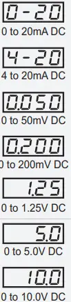 | -1999 to +9999 units | User settable 1 / 0.1 / 0.01/0.001 units |
FRONT PANEL LAYOUT
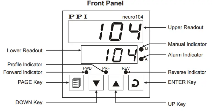
| Symbol | Key | Function |
 | PAGE | Press to enter or exit set-up mode. |
 | DOWN | Press to decrease the parameter value. Pressing once decreases the value by one count; keeping pressed speeds up the change. |
 | UP | Press to increase the parameter value. Pressing once increases the value by one count; keeping pressed speeds up the change. |
 | ENTER | Press to store the set parameter value and to scroll to the next parameter on the PAGE. |
PV Error Indications
| Message | PV Error Type |
 | Over-range (PV above Max. Range) |
 | Under-range (PV below Min. Range) |
 | Open (Sensor open / broken) |
![]() 101, Diamond Industrial Estate, Navghar,
101, Diamond Industrial Estate, Navghar,
Vasai Road (E), Dist. Palghar – 401 210.
Sales : 8208199048 / 8208141446
Support : 07498799226 / 08767395333
E: [email protected],
[email protected]


