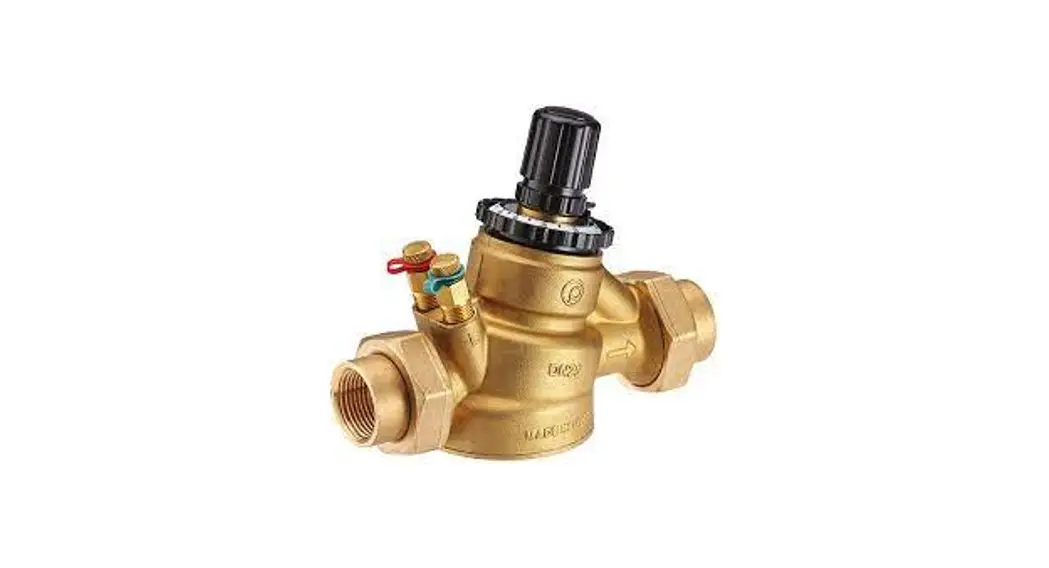
![]() VP1000 Compact Globe (Axial) 1/2 Inch to 1 1/4 Inch
VP1000 Compact Globe (Axial) 1/2 Inch to 1 1/4 Inch
(DN15-DN32)
Pressure Independent Control Valve
Instruction Manual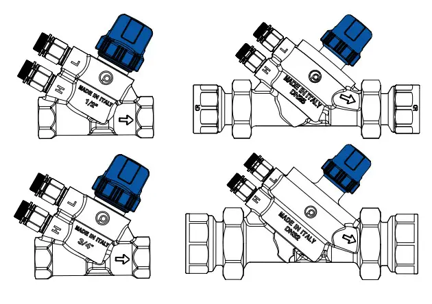
VP1000 Series Pressure Independent Control Valve
 Johnson Controls does not accept any liability for improper or wrong use of this product. Proper water treatment is recommended; refer to the VDI 2035 Guideline. Furthermore, maximum iron oxide in the water passing through control valve (PICV) should not exceed 25 mg/L (25 ppm). To ensure the main pipework is cleaned appropriately, flushing by-passes should be used without flushing through the pressure regulator of the Pressure Independent Control Valve.
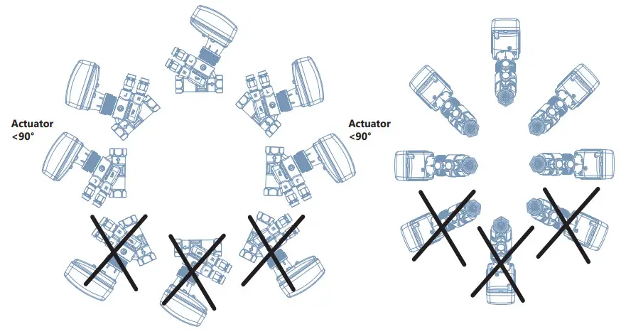
Mounting considerations for the technician
For more information about the VA-748x Electric Valve Actuators, see the latest revision of the installation instructions.
All VA-748x Series Electric Valve Actuators ship from the factory in the fully up position. If you have purchased the valve and actuator separately, before mounting the actuator, you must note the following:
- Do not remove the mounting instruction tag attached to the actuator body.
- Do not use the actuator as a lever to thread the valve body onto the piping.
- Ensure that the actuator is free from thermal insulating material.
- Allow a minimum clearance of 7/8 in. (22mm) above the actuator body.
- If the actuator was powered before mounting on the valve, you must return the actuator to its original upright position before proceeding.
- The actuator must be independently mounted in a vertical or horizontal position.
 Maintenance and cleaning
During valve cleaning operations, use a damp cloth as detergents, solvents or chemical product that may seriously damage or compromise the proper functioning and reliability of the valve and actuator.
Dimensions
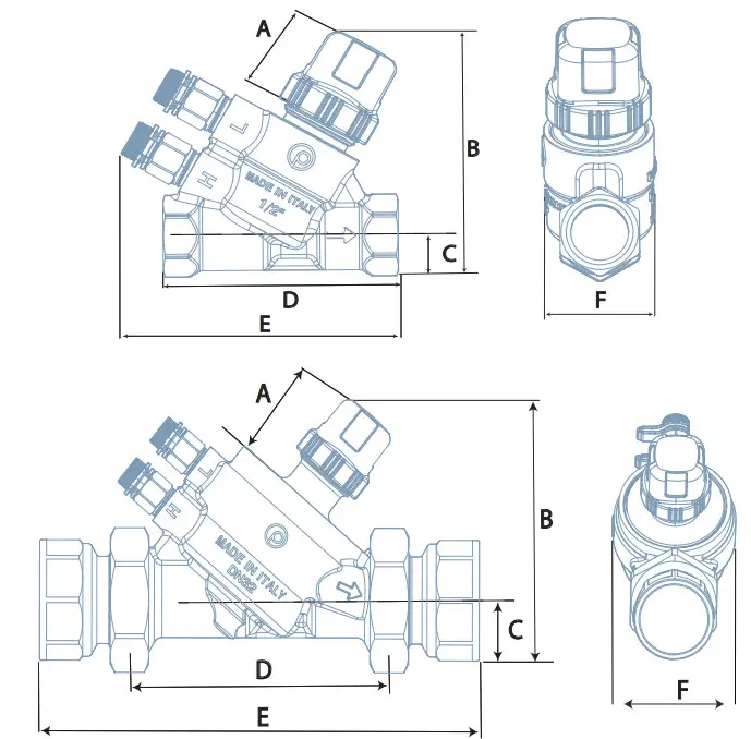
Table 1: Valve dimensions mm.
| Valve size | A | B | C | D | E | F | |
| VP10xHAA | 1/2” DN15 | 28 | 83 | 14.5 | 80.5 | 95 | 36 |
| VP10xHDA | 1/2” DN15 | 28 | 83 | 14.5 | 80.5 | 95 | 36 |
| VP10xHDC | 1/2” DN15 | 28 | 85 | 14.5 | 93.5 | 118 | 53 |
| VP10xJAJ | 3/4” DN20 | 28 | 88 | 17.5 | 98 | 118 | 56 |
| VP10xJDB | 3/4” DN20 | 28 | 88 | 17.5 | 98 | 118 | 56 |
| VP10xKDD | 1” DN25 | 41 | 99 | 24 | 108 | 182 | 60 |
| VP10xKDE | 1” DN25 | 41 | 99 | 24 | 108 | 182 | 60 |
| VP10xLDF | 1 1/4” DN32 | 41 | 113 | 30 | 120 | 194 | 76 |
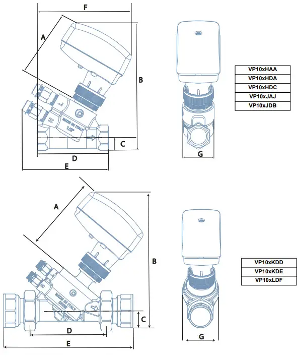 Table 2: Valve with VA-748x Series Actuator dimensions mm
| Valve size | A | B | C | D | E | F | G | |
| VP10xHAA | 1/2” DN15 | 80.5 | 145 | 14.5 | 80.5 | 95 | 106 | 37 |
| VP10xHDA | 1/2” DN15 | 80.5 | 145 | 14.5 | 80.5 | 95 | 106 | 37 |
| VP10xHDC | 1/2” DN15 | 80.5 | 147 | 14.5 | 93.5 | 118 | 110.5 | 53 |
| VP10xJAJ | 3/4” DN20 | 80.5 | 150 | 17.5 | 98 | 118 | 112.5 | 56 |
| VP10xJDB | 3/4” DN20 | 80.5 | 150 | 17.5 | 98 | 118 | 112.5 | 56 |
| VP10xKDD | 1” DN25 | 83 | 155 | 23.5 | 108 | 182 | – | 60 |
| VP10xKDE | 1” DN25 | 83 | 155 | 23.5 | 108 | 182 | – | 60 |
| VP10xLDF | 1 1/4” DN32 | 88 | 169 | 30 | 120 | 194 | – | 76 |
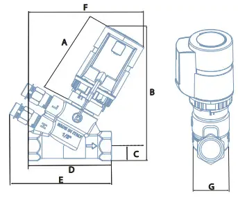 Table 3: Valve with VA-709x Series Actuator dimensions mm, DN15 and DN20 only
| Valve size | A | B | C | D | E | F | G | |
| VP10xHAA | 1/2” DN15 | 74 | 127 | 14.5 | 80.5 | 95 | 106 | 36 |
| VP10xHDA | 1/2” DN15 | 74 | 127 | 14.5 | 80.5 | 95 | 106 | 36 |
| VP10xHDC | 1/2” DN15 | 74 | 129 | 14.5 | 93.5 | 118 | 110.5 | 53 |
| VP10xJAJ | 3/4” DN20 | 74 | 132 | 17.5 | 98 | 118 | 112.5 | 56 |
| VP10xJDB | 3/4” DN20 | 74 | 132 | 17.5 | 98 | 118 | 112.5 | 56 |
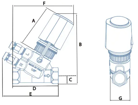 Table 4: Valve with VA-708x Series Actuator dimensions mm, DN15 and DN20 only
| Valve size | A | B | C | D | E | F | G | |
| VP10xHAA | 1/2” DN15 | 64.5 | 120 | 14.5 | 80.5 | 95 | 106 | 36 |
| VP10xHDA | 1/2” DN15 | 64.5 | 120 | 14.5 | 80.5 | 95 | 106 | 36 |
| VP10xHDC | 1/2” DN15 | 64.5 | 122 | 14.5 | 93.5 | 118 | 110.5 | 53 |
| VP10xJAJ | 3/4” DN20 | 64.5 | 125 | 17.5 | 98 | 118 | 112.5 | 56 |
| VP10xJDB | 3/4” DN20 | 64.5 | 125 | 17.5 | 98 | 118 | 112.5 | 56 |
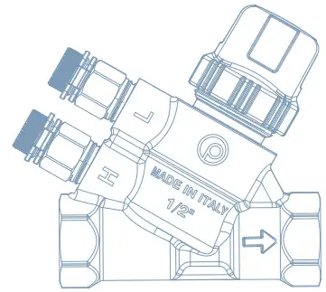
Flow direction
The following diagram illustrates the flow direction. Use this diagram as a guide for attaching the actuator. If flow reversal cannot be avoided, mount a check valve. See Table
6 for the minimum differential pressure required. Mounting in the wrong direction may damage the system and the valve.
Flow rate settings
Table 5: VP10xHxx, VP10xJxx, VP10xKxx and VP10xLxx
| VP10xHAA | VP10xHDA | VP10xHDC | VP10xJAJ | VP10xJDB | VP10xKDD | VP10xKDE | VP10xJDB | |
| Pre-setting | Flow l/h | Flow l/h | Flow l/h | Flow l/h | Flow l/h | Flow l/h | Flow l/h | Flow l/h |
| 9 | 150 | 450 | 850 | 1000 | 1850 | 2500 | 3300 | 5200 |
| 8 | 133.5 | 408 | 774 | 897 | 1734 | 2202 | 3046 | 4680 |
| 7 | 114 | 358 | 689 | 782 | 1548 | 1875 | 2682 | 4164 |
| 6 | 99.5 | 281 | 606 | 678 | 1320 | 1577 | 2265 | 3582 |
| 5 | 85 | 219 | 496 | 564 | 1080 | 1304 | 1849 | 2880 |
| 4 | 71 | 179 | 393 | 442 | 846 | 1048 | 1387 | 2220 |
| 3 | 55 | 135 | 331 | 359 | 624 | 798 | 884 | 1578 |
| 2 | 39.5 | 94 | 265 | 278 | 492 | 560 | 543 | 1026 |
| 1 | 19 | 53 | 157 | 154 | 276 | 339 | 173 | 540 |
| 0.5 | 9 | 32 | 62.5 | 45 | 174 | 165 | 76 | 265 |
| 0 | 0 | 0 | 0 | 0 | 0 | 0 | 0 | 0 |
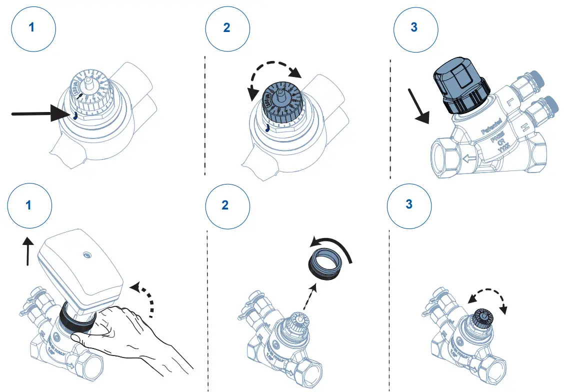
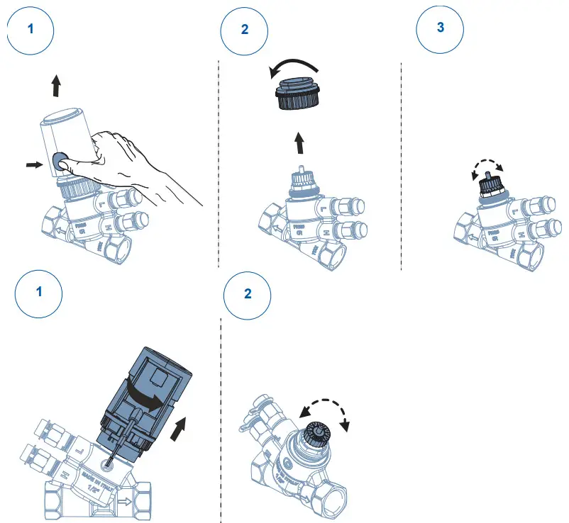
Pre-setting the maximum flow
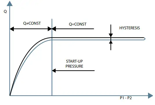
Measuring differential pressure
To ensure that the valve is working in the operating range, measure the differential pressure across the valve. The valve is in the operating range if the value at P1-P2 (ΔP) is higher than the start up value. If the ΔP measured value is lower than the start up value, then the valve works as a fixed orifice valve. Use the following table as reference for minimum differential pressure requirements. See Table 6 for minimum differential pressure requirements for each valve model.
Table 6: Minimum differential pressure requirements
| Valve codes | Start-up ΔP |
| VP10xHxx | |
| VP10xHAA | 25 kPa |
| VP10xHDA | 35 kPa |
| VP10xHDC | 25 kPa |
| VP10xJxx | |
| VP10xJAJ | 30 kPa |
| VP10xJDB | 35 kPa |
| VP10xKxx | |
| VP10xKDD | 30 kPa |
| VP10xKDE | 30 kPa |
| VP10xLxx | |
| VP10xLDF | 35 kPa |
Mounting the electro-mechanical actuator
The following instructions apply only to valves and actuators sold separately, and are not required for actuator assemblies.
Note: When mounting the actuator, ensure that it is in the upright position.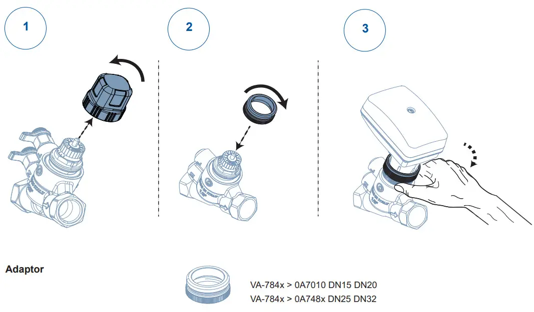
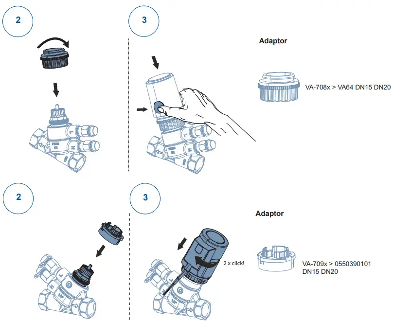
Note: For VA-748x, VA-708x and VA-709x literature visit www.solutionnavigator.com
Technical specifications
Table 1: VP10x Hxx 1/2” (DN15)
| VP10xHAA | VP10xHDA | VP10xHDC | |
| Flow rate max. (100% water) | 150 l/h | 450l/h | 850 l/h |
| Service | Water or water-glycol mixture (up to 50% glycol), quality to VDI 2035 | ||
| Accuracy up to 15 PSID = 100 kPa | ± 5% | ||
| Minimum ΔP for start-up | 25 kPa | 35 kPa | 25 kPa |
| Maximum ΔP | 600 kPa | ||
| Maximum working pressure | 2500 kPa | ||
| Close off pressure | 689 kPa | ||
| Temperature | -10 to 120 °C | ||
| Connection | Rp 1/2” F | ||
| Leakage | ANSI Class IV IEC 60534-4 | ||
| Compliance | Johnson Controls declares that these products are in compliance with the essential requirements and other relevant provisions of the PED (Pressure Equipment Directive) 2014/68/ UE (Paragraph 4, comma 3). CE Marking is not applicable. ROHS (95/2002/CE) | ||
Table 2: VP10x Jxx 3/4” (DN20)
| VP10xJAJ | VP10xJDB | |
| Flow rate max. (100% water) | 1,000 l/h | 1,850 l/h |
| Service | Water or water-glycol mixture (up to 50% glycol), quality to VDI 2035 | |
| Accuracy up to 15 PSID = 100 kPa | ± 5% | |
| Minimum ΔP for start-up | 30 kPa | 35 kPa |
| Maximum ΔP | 600 kPa | |
| Maximum working pressure | 2500 kPa | |
| Close off pressure | 689 kPa | |
| Temperature | -10 to 120 °C | |
| Connection | Rp 3/4” F | |
| Leakage | ANSI Class IV IEC 60534-4 | |
| Compliance | Johnson Controls declares that these products are in compliance with the essential requirements and other relevant provisions of the PED (Pressure Equipment Directive) 2014/68/UE (Paragraph 4, comma 3). CE Marking is not applicable. ROHS (95/2002/CE) | |
Table 3: VP10x Kxx 1” (DN25) and VP10x Lxx 1 1/4” (DN32)
| VP10xKDD | VP10xKDE | VP10xLDF | |
| Flow rate max. (100% water) | 2500 l/h | 3300 l/h | 5200 l/h |
| Service | Water or water-glycol mixture (up to 50% glycol), quality to VDI 2035 | ||
| Accuracy up to 15 PSID = 100 kPa | ± 5% | ||
| Minimum ΔP for start-up | 30 kPa | 30 kPa | 35 kPa |
| Maximum ΔP | 600 kPa | ||
| Maximum working pressure | 2500 kPa | ||
| Close off pressure | 689 kPa | ||
| Temperature | -10 to 120 °C | ||
| Connection | Rp 1” F | RC 1 1/4” F | |
| Leakage | ANSI Class IV IEC 60534-4 | ||
| Compliance | Johnson Controls declares that these products are in compliance with the essential requirements and other relevant provisions of the PED (Pressure Equipment Directive) 2014/68/UE (Paragraph 4, comma 3). CE Marking is not applicable. ROHS (95/2002/CE) | ||
![]() WARNING This product is made of copper alloy, which contains lead.
WARNING This product is made of copper alloy, which contains lead.
The product is therefore not to be used on drinking water.![]() WARNING This product can expose you to chemicals including lead, which is known to the State of California to cause cancer, birth defects, or other reproductive harm. For more information, go to www.P65Warnings.ca.gov.
WARNING This product can expose you to chemicals including lead, which is known to the State of California to cause cancer, birth defects, or other reproductive harm. For more information, go to www.P65Warnings.ca.gov.
WARNING: BRASS MAY CONTAIN LEAD
To fulfill our obligations towards Article 33, in accordance to the European REACH Regulation No 1907/2006 EC, we hereby inform you that this article contains the following Substances of Very High Concern mentioned on the Candidate list:
- Lead
| UK Single Point of Contact | European Single Point of Contact | NA/SA Single Point of Contact | APAC Single Point of Contact |
| JOHNSON CONTROLS TYCO PARK GRIMSHAW LANE MANCHESTER M40 2WL UNITED KINGDOM | JOHNSON CONTROLS VOLTAWEG 20 6101 XK ECHT THE NETHERLANDS | JOHNSON CONTROLS 5757 N GREEN BAY AVE GLENDALE, WI 53209 USA | JOHNSON CONTROLS C/O CONTROLS PRODUCT MANAGEMENT NO. 32 CHANGJIANG RD NEW DISTRICT WUXI JIANGSU PROVINCE 214028 CHINA |
![]()
Building Technologies & Solutions
5757 N Green Bay Ave, Glendale, WI 53209
www.johnsoncontrols.com
Metasys® and Johnson Controls® are
registered trademarks of Johnson Controls.
All other marks herein are the marks of their respective owners.
© 2022 Johnson Controls.
P/N 34-636-02537, Rev. B


