Johnson Controls SDP2500 Differential Pressure Transmitter Instruction Manual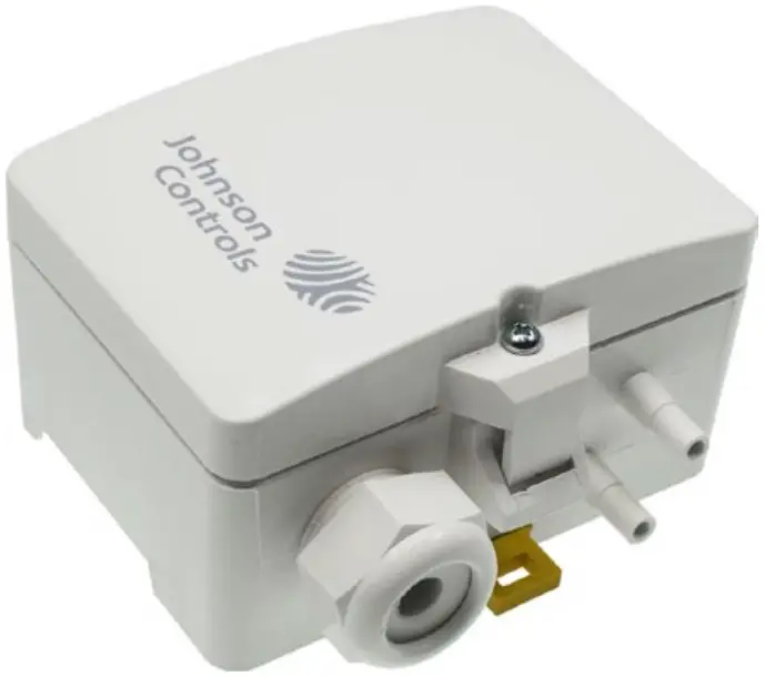
Application
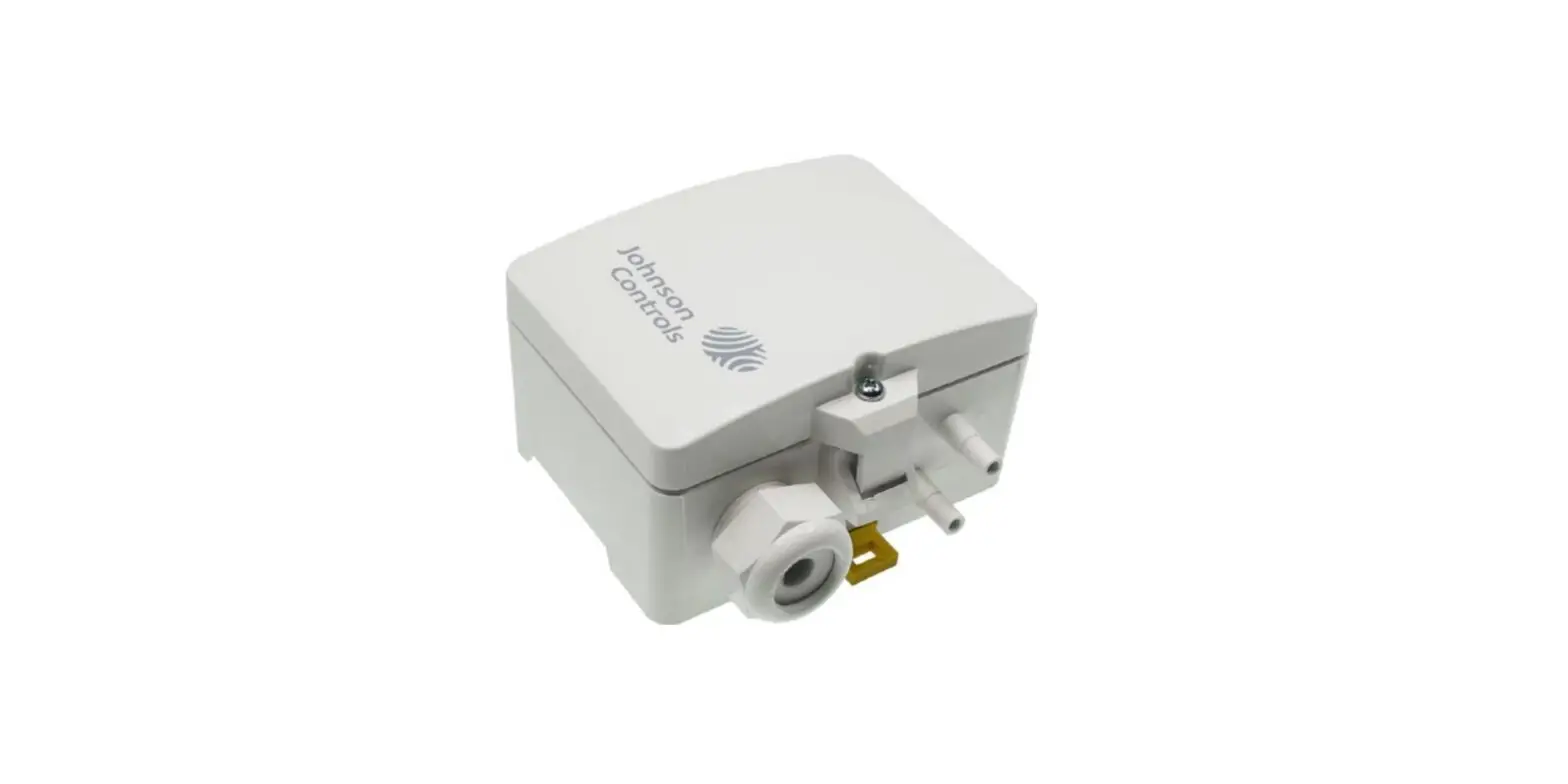
Differential pressure transmitter with 8 selectable ranges and 0..10 V output. For monitoring of differential pressure in air and other non-flammable and non-aggressive gases. Possible applications: Monitoring of air filters, fans, industrial cooling air cycles as well as overheating protection, control of air and fire damper actuators. Screw-mounted onto flat surface, prepared for mounting on DIN rail TS35 (35×7,5 mm) according to EN 60715.
Solution
Security Advice
![]() The installation and assembly of electrical equipment should only be performed by authorized personnel.
The installation and assembly of electrical equipment should only be performed by authorized personnel.
The product should only be used for the intended application. Unauthorised modifications are prohibited! The product must not be used in relation with any equipment that in case of a failure may threaten, directly or indirectly, human health or life or result in danger to human beings, animals or assets. Ensure all power is disconnected before installing. Do not connect to live/operating equipmen
Please comply with
- Local laws, health & safety regulations, technical standards and regulations
- Condition of the device at the time of installation, to ensure safe installation
- This data sheet and installation manual
Before mounting, commissioning and operation make sure that the right pressure gauge has been selected in terms of measuring range, design and, due to the specific measuring conditions, the suitable wetted medium. Only install and maintain pressure gauges by qualified personnel authorized by the plant operator. Failure to comply with applicable regulations may result in serious personal injury and / or property damage.
 Notes on Disposal
As a component of a large-scale fixed installation, JCI products are intended to be used permanently as part of a building or a structure at a pre-defined and dedicated location, hence the Waste Electrical and Electronic Act (WEEE) is not applicable. However, most of the products may contain valuable materials that should be recycled and not disposed of as domestic waste. Please note the relevant regulations for local disposal.
 EU conformity
Johnson Controls, Inc., declares that these products are in compliance with the essential requirements and other relevant provisions of the EMC Directive and Rohs Directive.
Enclosure with UV and weather protection
After some time, outdoor mounted plastics can lose their color and quality. Therefore, all hinged cover enclosures are made of special white polycarbonate (PC). The light-stable colorants and additives are used to achieve optimum protection of the polymer while maintaining color stability. The titanium dioxide used is especially developed for polycarbonate and offers excellent UV protection through the reflection of the entire light spectrum including the UV component around 340 nm. This effectively counteracts the otherwise occurring photochemical polymer degradation. The color intensity is preserved for a long time without fading. The material is also resistant to cold and frost.
Technical Specifications
| Models | SDP2500-R8 | 0..10V |
| SDP2500-R8-AZ | 0..10V, AZ | |
| SDP2500-R8-D | 0..10V, with LCD | |
| SDP2500-R8-AZ-D | 0..10V, AZ, with LCD | |
| SDP2500-C4-AZ-D | 0..10V, AZ, with LCD, Calibration certificate – 0, 250, 500Pa | |
| SDP2500-C5-AZ | 0..10V, AZ, Calibration certificate – 0, +500, +1000Pa | |
| SDP2500-C5-AZ-D | 0..10V, AZ, with LCD, Calibration certificate – 0, +500, +1000Pa | |
| SDP2500-C6-AZ-D | 0..10V, AZ, with LCD, Calibration certificate – 0, +750, +1000Pa | |
| SDP2500-C8-AZ | 0..10V, AZ, Calibration certificate – 0, +1250, +2500Pa | |
| Power supply | 15..24 V = (±10%) or 24 V ~ (±10%) SELV | |
| Power consumption | typ. 1,1 W (24 V =) | 1,7 VA (24 V ~) | |
| Measuring range pressure | -100..+100 | 0..+100 | 0..+250 | 0..+500 | 0..+1000 | 0..+1500 |0..+2000 | 0..+2500 Pa (default) | |
| Analogue output | 0..10 V, min. load 10 kΩ | |
| Accuracy pressure | deviation compared to the reference devicemeasuring range ≤500 Pa: ±5 Pa,measuring range >500 Pa: ±10 Pa | |
| Max. working overpressure | 400 kPa | |
| Display | LCD 37,5×31,6 mm, measured values: Pa | |
| Enclosure | hinged cover enclosure, PC, pure white (with LCD, transparent cover) | |
| Protection | IP54 according to EN 60529, IP65 with bolted cover | |
| Cable entry | M20 for cable max. Ø=8 mm,seal insert for double cable entry for wire max Ø=6 mm | |
| Connection electrical | Terminal block, max. 1,5 mm² | |
| Ambient condition | -10..+50 °C, max. 85% rH, short term condensation | |
| Storage condition | -30..+70 °C, max. 85% rH, short term condensation | |
| Mounting | Screw-mounted onto flat surface, prepared for mounting on DIN rail TS35 (35×7,5 mm) according to EN 60715 | |
Mounting
Before installing the device, please check all pressurized tubes for tightness.
AZ – Automatic Zero-Point Calibration (optional)
Initial Power ON: Once the device is powered up, the Auto-zero reset will be performed multiple times in intervals shorter than 10mins (contrary to the operational mode). This is to compensate the self-heating of the sensor and PCB after start up and to provide accurate measurements throughout. After around 30mins, the device goes fully into operational mode.
Transmitters equipped with the automatic zero-point correction are maintenance-free.
The auto-zero calibration electronically adjusts the transmitter to zero every 10 minutes. The function eliminates all output signal drifts due to thermal, electronic or mechanical effects. The auto-zero adjustment takes approx. 4 seconds after which the device returns to its normal operation. During the 4 seconds correction phase, the output and display values will freeze to the last measured value. After the zero pointcorrection, display values and output signal go back into live mode.
Connection
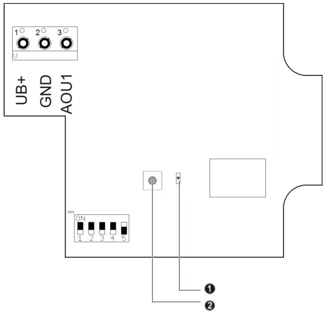
| 1 | UB+ | 15..24 V = (±10%) or 24 V ~ (±10%) |
| 2 | GND | GND |
| 3 | AOU1 | 0..10 V | differential pressure |
UB+ → Power supply 24V
GND → Ground
AOUx → Analog output 0..10 V
DIP 1..DIP 3 Measuring ranges
| DIP 1 | DIP 2 | DIP 3 | Range |
| OFF | OFF | OFF | 0..+2500 Pa (default setting) |
| ON | OFF | OFF | 0..+2000 Pa |
| OFF | ON | OFF | 0..+1500 Pa |
| ON | ON | OFF | 0..+1000 Pa |
| OFF | OFF | ON | 0..+500 Pa |
| ON | OFF | ON | 0..+250 Pa |
| OFF | ON | ON | 0..+100 Pa |
| ON | ON | ON | -100..+100 Pa |
DIP 4 Response time
| DIP 4 | Response time |
| OFF | 4 s (default setting) |
| ON | 10 s |
DIP 5 Display settings
| DIP 5 | LCD Backlight |
| OFF | Backlight OFF |
| ON | Backlight ON (default setting) |
- Status (Power LED)
- Button for manual zero point correction During normal operation, a manual zero point correction should be performed every 12 months. Attention! In order to perform the manual zero point correction properly, the power supply must be connected at least one hour before.
- Remove both connection tubes from the pressure terminals + and –
- Press the button until the LED lights up permanently
- Wait until the LED flashes again and reinstall the connection tubes to the pressure terminals (pay attention to + and -)
Dimensions (mm)
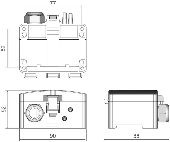
In order to reach IP 65 protection according to EN 60527, the cover has to be bolted e.g. using a screw 3,5×10 mm according to EN 7981.
UK Single Point of Contact
Johnson Controls TYCO Park Grimshaw Lane MANCHESTER M40 2WL United Kingdom
EU Single Point of Contact
ohnson Controls Voltaweg 20 6101 XK Echt The Netherlands
APAC Single Point of Contact
JOHNSON CONTROLS C/O CONTROLS PRODUCT MANAGEMENT NO. 32 CHANGJIANG RD NEW DISTRICT WUXI JIANGSU PROVINCE 214028 CHINA
www.johnsoncontrols.com
www.johnsoncontrols.com/locations
Metasys® and Johnson Controls® are registered trademarks of Johnson Controls.
All other marks herein are the marks of their respective owners. © 2023 Johnson Controls.