![]() NP785 Ultra Low Differential
NP785 Ultra Low Differential
Pressure Transmitter 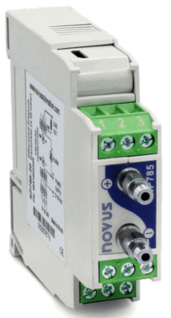 INSTRUCTION MANUAL V1.0x G
SAFETY ALERTS
The symbols below are used in the device and throughout this manual to draw the user’s attention to important information related to device safety and use.
 | ||
| CAUTION Read the manual fully before installing and operating the device. | CAUTION OR HAZARD Risk of electric shock. | ATTENTION Material sensitive to static charge. Check precautions before handling. |
All safety recommendations appearing in this manual must be followed to ensure personal safety and prevent damage to the instrument or system.
If the instrument is used in a manner other than that specified in this manual, the device’s safety protections may not be effective.
PRESENTATION
The NP785 Ultra Low Differential Pressure Transmitter uses a high precision differential pressure sensor and has the stability required to perform measurements in applications that require high sensitivity. It is a micro processed device with two communication interfaces: USB and RS485 via Modbus RTU protocol. The magnitude read by the sensor is provided through any of its interfaces, converted to a selected pressure unit from a set of options.
This equipment has a digital alarm output, which supports the configuration of the alarm condition, adjustable set points and custom timing, among other functions. Its transmission output can be configured to operate in the 0-10 V and 4-20 mA standards, with adjustable range within the sensor limits, and has adjustable behavior options in case of sensor error.
NXperience software offers a quick and intuitive way to configure of all equipment features. It is also possible to carry out the monitoring and obtain the diagnosis of the information downloaded.
The NP785 Ultra Low Differential Pressure Transmitter is suitable for use in HVAC applications such as environmental monitoring or climate control or environmental monitoring of industrial processes where high accuracy is required at low pressure ranges.
IDENTIFICATION
3.1 DEVICE IDENTIFICATION
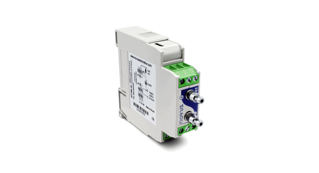
The identification of the device model is described on its side label, together with information regarding its electrical connections and its serial number. Fig. 01 shows the information available in the device housing:
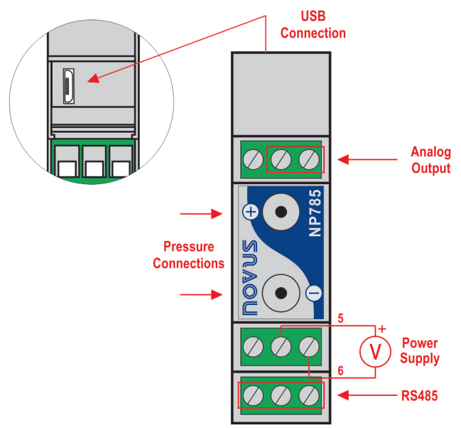 Fig. 01 – NP785 Ultra Low Differential Pressure Transmitter
3.2 DEVICE MODEL
In order to adapt to the most varied market needs, the NP785 Ultra Low Differential Pressure Transmitter line is available in two models:
• Model NP785-05 of ± 5 mbar.
• Model NP785-20 of ± 20 mbar.
| Model | Minimal Pressure | Maximal Pressure | Unit | Burst Pressure | Standard Configuration |
| 5 mbar | -5.000 | 5.000 | mbar | ±200 mbar | x |
| -72.52 | 72.52 | mpsi | |||
| -2.007 | 2.007 | in H2O | |||
| -50.98 | 50.98 | mm H2O | |||
| -500.0 | 500.0 | Pa | |||
| 20 mbar | -20.000 | 20.000 | mbar | ±400 mbar | x |
| -290.08 | 290.08 | mpsi | |||
| -8.029 | 8.029 | in H2O | |||
| -203.94 | 203.94 | mm H2O | |||
| -2000.0 | 2000.0 | Pa |
INSTALATION
4.1 MECHANIC INSTALATION
The NP785 Ultra Low Differential Pressure Transmitter is designed to have its housing fixed to a 35 mm DIN rail, as shown in Fig. 02. The 35 mm DIN rail installation must be carried out after the device has been configured.
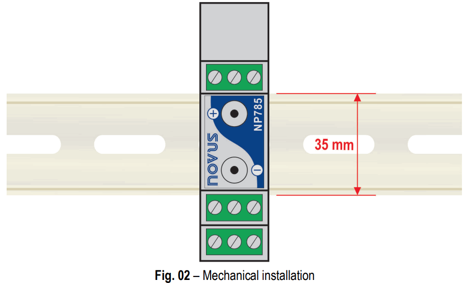
Installation recommendations:
- The pneumatic hoses must be installed after the device has been fitted to the 35 mm DIN rail.
- In order to avoid problems with condensation, the device must be installed above the point to be measured.
- The extension of the hoses does not affect the device accuracy. Very long hoses, however, can result in measurement delays.
- Hoses should not be bent or sharp curves should not be taken. Such actions may result in airflow interruption and possible sensor reading blockage.
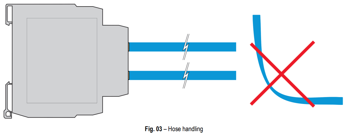
The hose do not come with the device.
Overpressure: Excessive pressure, which exceeds the NP785 Ultra Low Differential Pressure Transmitter capacity, can cause irreversible mechanical and electrical damage to the device. In order to avoid damaging the operator or the device installer, follow the installation instructions and use the appropriate protection and device.
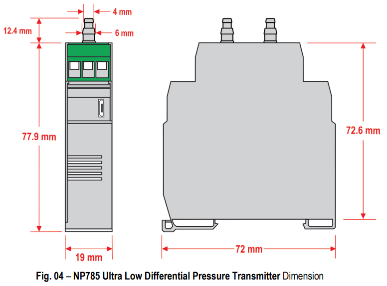
4.1.1 DIMENSION
Fig. 04 shows the dimensions of the device:
4.2 ELECTRICAL INSTALLATION
4.2.1 RECOMMENDATIONS FOR INSTALLATION
- Signal conductors should run through the plant separately from the power supply and output conductors. If possible, in grounded conduits.
- The power supply for electronic instruments must come from an appropriate grid for instruments.
- RC FILTERS (noise suppressor) are recommended in contactor coils, solenoids, etc.
- In control applications, it’s essential to consider what could happen when some part of the system fails. The device’s internal devices do not ensure total protection.
- Grounding helps limit the effects of noise due to electromagnetic interference (EMI). Run the grounding connection by using the grounding bolt and the grounding plane before turning on the device.
4.2.2 SPECIAL PRECAUTION
Because it is an electronic module, the device needs some care when handling:
- Due to the risk of damage caused by static electricity and may occur if the electronic circuit is exposed, the device should not be opened.
- Pay close attention when connecting the wires.
- Remember to pass all wires through a cable clip before completing electrical connections.
- When closing the housing, the cover should be placed again properly, ensuring proper sealing for this device.
4.2.3 ELECTRICAL CONNECTIONS
Fig. 05 shows the device electrical connections:
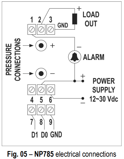
| Electrical Connection | Input | |
| Output | 1 | ALARM |
| 2 | OUT (Retransmission) | |
| 3 | GND | |
| Power Supply | 4 | NC |
| 5 | POWER | |
| 6 | GND | |
| RS485 | 7 | D1 (D) |
| 8 | D0 () | |
| 9 | GND |
Table 02 – Electrical connections
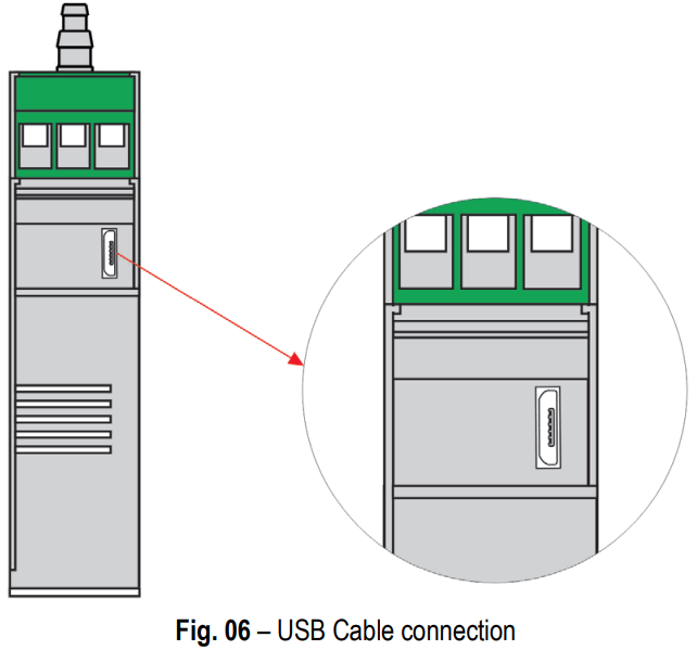
4.2.4 USB CONNECTION
The USB connection is used exclusively for the device diagnosis and configuration. The USB interface is on the NP785 Ultra Low Differential Pressure Transmitter side.
It is recommended that the device be configured before it is attached to the DIN rail.
For more information, check the USB Interface chapter.
CONFIGURATION
The NP785 Ultra Low Differential Pressure Transmitter is configurable by any of its interfaces. Due to the ease of use of the interface, it is recommended to configure via USB using the NXperience software, but the device can also be configured via Modbus RTU by writing directly in their configuration registers.
The description of the device registers, together with the configuration tables, can be found in the Serial Communication chapter.
5.1 GENERAL CONFIGURATION
The purchase of the pressure value is done in digital analogue analysis solutions of the internal sensor of the device. You can select the pressure unit to be used from the following options: mbar, mpsi, in H2O, mm H2O or Pa. Changes in this setting cause transmission limits and alarm set points to be reverted to the default values, which are the operating limits of the device.
The device also has an Offset function and an internal digital filter for treatment of the measured signal. An offset value can be set, which will be described on the selected pressure unit, to make small adjustments to the output value. The digital filter allows you to set a time interval, in seconds, to reduce the occurrence of noise effects and peaks of pressure over a faster response.
It is also possible to configure the Modbus RTU communication parameters, such as Baud Rate, parity and slave address of the device.
For purposes of differentiation between units of the same model, an identifier can be configured in the device.
For testing purposes, the device supports forcing differential pressure measurement, analog output and alarm output. For each of these cases, you can configure a value to be forced and enable or disable the forcing.
5.2 ALARM CONFIGURATION
The NP785 Ultra Low Differential Pressure Transmitter has a digital alarm output. The digital output will be activated whenever an alarm situation is satisfied, except in particular cases defined by some of its settings.
You can configure the alarm operation mode, high and low set points, hysteresis value, state transition timers, error condition and initial blocking.
Alarm configuration can be performed using the NXperience software (see the Output Parameter section ), allowing different modes of operation:
- Off: No alarm situation is active.
- Sensor Error: While there is some error reading the sensor, the alarm output will remain on.
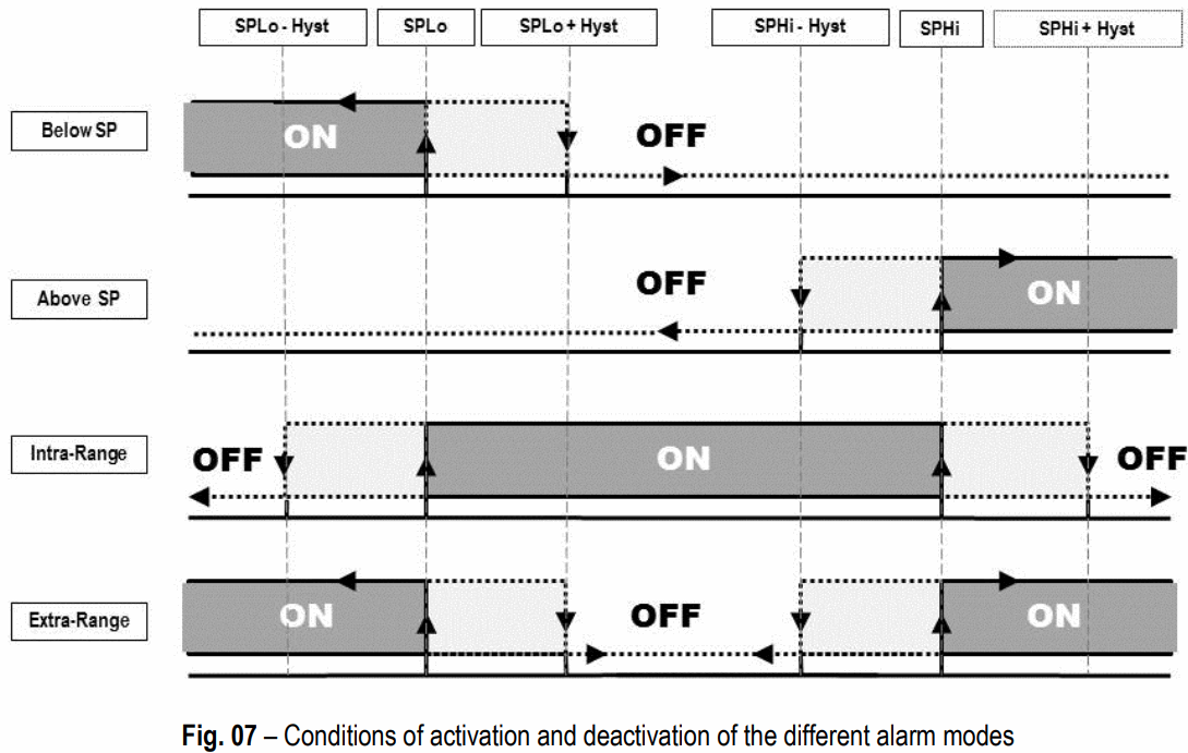
- Below Lower Setpoint: The alarm output will be triggered when the current pressure is lower than the lower set point. To exit the alarm condition, the differential pressure must be greater than the lower set point plus the hysteresis value.
- Above Higher Setpoint: The alarm output will be triggered when the differential pressure is higher than the upper set point. To exit the alarm condition, the differential pressure must be lower than the lower set point minus the hysteresis value.
- Intra-range: The alarm output will be activated when the differential pressure is higher than the lower set point and lower than the upper set point. To exit the alarm condition, the differential pressure must be greater than the upper set point plus the hysteresis value or lower than the lower set point minus the hysteresis value.
- Extra-range: The alarm output will be activated when the differential pressure is higher than the set point higher or lower than the lower set point. To exit the alarm condition, the differential pressure must be less than the upper set point minus the hysteresis value and higher than the lower set point plus the hysteresis value.
In addition to the alarm operation modes, other parameters, which do not apply to the Sensor Error mode, can be configured to refine the behavior of the alarm output:
- Initial Blocking: This parameter determines the use of the alarm output lock soon after the device is started. After initialization, a non-alarm condition is required for the alarm output to be enabled.
- Error Condition: The status of this parameter determines whether the alarm output will remain on or off in case of sensor failure.
- Hysteresis: This parameter stores the pressure value that, with the values of the set points, determines the limit value to leave the alarm situation. Fig. 07 shows the conditions for alarm activation and deactivation.
The alarm output can be timed by means of the Time On and Time Off parameters. For a given state transition to occur, the device must remain in the new state for a period of time equal to the one configured in the respective transition parameter. These values are initialized to 0 by default.
Extra-range mode is the default mode of alarm output. The default values of the set points, in turn, are the operating limits of the device. Any changes in the pressure unit configuration readjust the values of the set points to the operating limits.
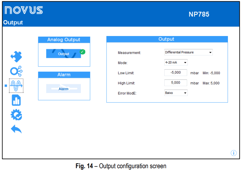
5.3 ANALOG OUTPUT CONFIGURATION
The device has a configurable analog output. You can configure it using the NXperience software (check the Output Parameters section), and you can define: the electrical pattern, the error mode and the excursion range of the pressure to be transmitted.
The electrical pattern can be selected between 0-10 V and 4-20 mA modes and the error mode determines the behavior of the analog output in case of sensor failure, as shown in Table 03:
| Error Mode | |||
| Mode | Low | High | Low/High* |
| 0 – 10 V | 0 V | 10 V | < Minimum Limit à 0 V |
| Sensor error à 10 V | |||
| > Maximum Limit à 10 V | |||
| 4 – 20 mA | 3.6 mA | 21.0 mA | < Minimum Limit à 3.6 mA |
| Sensor error à 21.0 mA | |||
| > Maximum Limit à 21.0 mA | |||
Table 03 – Behavior of the analog output in case of sensor failure
* Available starting with firmware version 1.20 and software version 2.0.6.02.
The excursion of the electric signal respects the values set in the configuration of the lower and upper transmission limits, which allows customizing the differential pressure range. The factory setting also defines the upper and lower limits of the sensor as the maximum operating limits of each respective model.
The device is factory set with the 4-20 mA electrical standard and the pressure unit in mbar. Any changes in the pressure unit configuration readjust the values of the transmission limits to the operating limits of the device.
USB INTERFACE
The USB interface is used for CONFIGURING or MONITORING the device.
For CONFIGURATION, you must use the NXperience software to create, view, save, and open configurations from the device or files on your computer. The feature to save and open configurations in files makes it possible to transfer configurations between devices and make backup copies.
NXperience allows you to update the NP785 Ultra Low Differential Pressure Transmitter firmware (internal software) via USB interface.
For MONITORING, any supervision (SCADA) or laboratory software that supports Modbus RTU communication over a serial communication port can be used. When connected to a computer USB port, NP785 Ultra Low Differential Pressure Transmitter is recognized as a conventional serial port (COM x). Use NXperience or refer to the Device Manager on Windows Control Panel to identify the COM port assigned to the device.
Refer to the Modbus memory mapping in the device communication manual and its supervision software documentation to perform MONITORING.
Follow the procedure below to use the device USB communication:
- Download NXperience from our website and install it on your computer (see chapter NXperience Software). The USB drivers required for communication will be installed along with the software.
- Connect the USB cable between the device and the computer. The device doesn’t need a power supply. The USB will provide enough power for the communication operation (other device functions may not operate).
- Launch NXperience, configure the communication and start the device recognition.
The USB interface IS NOT ISOLATED from the retransmission output and alarm output. Its purpose is temporary use during CONFIGURATION and MONITORING periods. For the safety of people and device, it should only be used with the device fully disconnected from the external power supply input.![]() In any other situation, the USB interface use is possible, but requires a careful analysis by the person responsible for its installation.
In any other situation, the USB interface use is possible, but requires a careful analysis by the person responsible for its installation.
For MONITORING for long periods and with inputs and outputs connected, it is recommended to use the RS485, available or optional in most of our device.
SERIAL COMMUNICATION
The NP785 Ultra Low Differential Pressure Transmitter can be recognized on an RS485 network with Modbus RTU protocol as a slave device. All the configurable parameters of the device can be read and/or written via serial communication.
The device supports writing in Broadcast mode, using the slave address Modbus 0.
The available Modbus commands are as follows:
03 – Read Holding Register
05 – Write Single Coil
06 – Write Single Register
16 – Write Multiple Register
7.1 REGISTERS TABLE
| NP785-05 Model: Output Registers Table | ||||||||
| Address | Name | Description | R/W | Type | Standard | Min. | Max. | Decimal Places |
| 0 | HR_PRESS | Differential pressure value | RO | nt_32 | 0 | -5 mbar -72,52 mpsi -2,007 inH2O -50,98 mmH2O -500,0 Pa | 5 mbar 72,52 mpsi 2,007 inH2O 50,98 mmH2O 500,0 Pa | mbar: 3 decimal places mpsi: 2 decimal places inH2O: 3 decimal places mmH2O: 2 decimal places Pa: 1 decimal place |
| 1 | HR_PRESS_H | |||||||
| 2 | HR_PRESS_MIN | Minimum differential pressure value logged | RO | int_32 | 0 | -5 mbar -72,52 mpsi -2,007 inH2O -50,98 mmH2O -500,0 Pa | 5 mbar72,52 mpsi 2,007 inH2O 50,98 mmH2O 500,0 Pa | mbar: 3 decimal places mpsi: 2 decimal places inH2O: 3 decimal places mmH2O: 2 decimal places Pa: 1 decimal place |
| 3 | HR_PRESS_MIN_H | |||||||
| 4 | HR_PRESS_MAX | Maximum differential pressure value logged | RO | int_32 | 0 | -5 mbar -72,52 mpsi -2,007 inH2O -50,98 mmH2O -500,0 Pa | 5 mbar 72,52 mpsi 2,007 inH2O 50,98 mmH2O 500,0 Pa | mbar: 3 decimal places mpsi: 2 decimal places inH2O: 3 decimal places mmH2O: 2 decimal places Pa: 1 decimal place |
| 5 | HR_PRESS_MAX_H | |||||||
Table 04 – NP785-05 Model: Output Registers Table
| NP785-05 Model: Configuration Registers Table | ||||||||
| Address | Name | Description | R/W | Type | Standard | Min. | Max. | Decimal Places |
| 100 | HR_SENSOR_TYPE | Sensor type: 5 mbar or 20 mbar | RO | uint16 | 0 | 0 | 1 | N.A. |
| 101 | HR_OUT1_TYPE | Retransmission output type* | RW | uint16 | 0 | 0 | 1 | N.A. |
| 103 | HR_OUT1_IN_HIGH_LIMIT | mbar: 3 decimal places | ||||||
| 104 | HR_OUT1_IN_HIGH_LIMIT_H | Retransmission upper limit input | RW | int_32 | 5 mbar 72,52 mpsi 2,007 inH2O 50,98 mmH2O | -5 mbar -72,52 mpsi -2,007 inH2O -50,98 mmH2O | 5 mbar 72,52 mpsi 2,007 inH2O 50,98 mmH2O | mpsi: 2 decimal places inH2O: 3 decimal places |
| 500,0 Pa | -500,0 Pa | 500,0 Pa | mmH2O: 2 decimal places | |||||
| Pa: 1 decimal place | ||||||||
| 105 | HR_OUT1_IN_LOW_LIMIT | mbar: 3 decimal places | ||||||
| 106 | HR_OUT1_IN_LOW_LIMIT_H | Retransmission lower limit input | RW | int_32 | -5 mbar -72,52 mpsi -2,007 inH2O -50,98 mmH2O | -5 mbar -72,52 mpsi -2,007 inH2O -50,98 mmH2O | 5 mbar 72,52 mpsi 2,007 inH2O 50,98 mmH2O | mpsi: 2 decimal places inH2O: 3 decimal places |
| -500,0 Pa | -500,0 Pa | 500,0 Pa | mmH2O: 2 decimal places | |||||
| Pa: 1 decimal place | ||||||||
| 107 | HR_OUT1_ERR | Error type (higher, lower or low/high)* | RW | uint16 | 1 | 0 | 2 | N.A. |
| 108 | HR_OUT1_HIGH_LIMIT | Retransmission upper limit | RO | int_32 | 5 mbar 72,52 mpsi 2,007 inH2O 50,98 mmH2O 500,0 Pa | -5 mbar -72,52 mpsi -2,007 inH2O -50,98 mmH2O -500,0 Pa | 5 mbar 72,52 mpsi 2,007 inH2O 50,98 mmH2O 500,0 Pa | mbar: 3 decimal places mpsi: 2 decimal places inH2O: 3 decimal places mmH2O: 2 decimal |
| 109 | HR_OUT1_HIGH_LIMIT_H | |||||||
| places Pa: 1 decimal place | ||||||||
| 110 | HR_OUT1_LOW_LIMIT | Retransmission lower limit | RO | int_32 | -5 mbar -72,52 mpsi -2,007 inH2O -50,98 mmH2O -500,0 Pa | -5 mbar -72,52 mpsi -2,007 inH2O -50,98 mmH2O -500,0 Pa | 5 mbar | mbar: 3 decimal places mpsi: 2 decimal places inH2O: 3 decimal places mmH2O: 2 decimal places Pa: 1 decimal places |
| 111 | HR_OUT1_LOW_LIMIT_H | |||||||
| 113 | HR_PRESS_FLTR | Filter for differential pressure reading | RW | uint16 | 0 | 0 | 300 | 0 |
| 115 | HR_UNIT_SYSTEM | Units configuration* | RW | uint16 | 0 | 0 | 4 | N.A. |
| 122 | HR_A1FU | Alarm type* | RW | uint16 | 5 | 0 | 5 | N.A. |
| 123 | HR_A1SPHI_IN | Alarm Setpoint High Input | RW | int_32 | 0 | -5 mbar -72,52 mpsi -2,007 inH2O -50,98 mmH2O -500,0 Pa | 5 mbar 72,52 mpsi 2,007 inH2O 50,98 mmH2O 500,0 Pa | mbar: 3 decimal places mpsi: 2 decimal places inH2O: 3 decimal places mmH2O: 2 decimal places Pa: 1 decimal place |
| 124 | HR_A1SPHI_IN_H | |||||||
| 125 | HR_A1SPLO_IN | Alarm Setpoint Low Input | RW | int_32 | 0 | -5 mbar -72,52 mpsi -2,007 inH2O -50,98 mmH2O -500,0 Pa | 5 mbar 72,52 mpsi 2,007 inH2O 50,98 mmH2O 500,0 Pa | mbar: 3 decimal places mpsi: 2 decimal places inH2O: 3 decimal places mmH2O: 2 decimal places Pa: 1 decimal place |
| 126 | HR_A1SPLO_IN_H | |||||||
| 127 | HR_A1BL | Alarm block | RW | uint16 | 0 | 0 | 1 | N.A. |
| 128 | HR_A1HY | Alarm hysteresis | RW | uint16 | 0 | 0 | 1 mbar 14,50 mpsi 0,401 inH2O 10,20 mmH2O 100,0 Pa | mbar: 3 decimal places mpsi: 2 decimal places inH2O: 3 decimal places mmH2O: 2 decimal places Pa: 1 decimal place |
| 129 | HR_A1T1 | Alarm time ON | RW | uint16 | 0 | 0 | 6500 | 0 |
| 130 | HR_A1T2 | Alarm time OFF | RW | uint16 | 0 | 0 | 6500 | 0 |
| 131 | HR_A1IERR | Determines the alarm status in case of sensor error | RW | uint16 | 0 | 0 | 1 | N.A. |
| 132 | HR_A1SPHI | Alarm Setpoint High | RO | int_32 | 0 | -5 mbar -72,52 mpsi -2,007 inH2O -50,98 mmH2O -500,0 Pa | mbar 72,52 mpsi 2,007 inH2O 50,98 mmH2O 500,0 Pa | mbar: 3 decimal places mpsi: 2 decimal places inH2O: 3 decimal places mmH2O: 2 decimal places Pa: 1 decimal place |
| 133 | HR_A1SPHI_H | |||||||
| 134 | HR_A1SPLO | Alarm Setpoint Low | RO | int_32 | 0 | -5 mbar -72,52 mpsi -2,007 inH2O -50,98 mmH2O -500,0 Pa | 5 mbar 72,52 mpsi 2,007 inH2O 50,98 mmH2O 500,0 Pa | mbar: 3 decimal places mpsi: 2 decimal places inH2O: 3 decimal places mmH2O: 2 decimal places Pa: 1 decimal place |
| 135 | HR_A1SPLO_H | |||||||
| 137 | HR_BAUD | Baud Rate* | RW | uint16 | 4 | 0 | 7 | N.A. |
| 138 | HR_PRTY | Parity* | RW | uint16 | 0 | 0 | 2 | N.A. |
| 139 | HR_ADDR | Slave address | RW | uint16 | 1 | 1 | 247 | N.A. |
| ## | HR_OFST_PRESS | Ureter,. pressure Offset | RW | uin116 | .1 mi. -14.50 mPT, -0,401 k1H20 -10,20 mmH20 -100.0 Pa | 1 mbar 14 50 mpsi 0,401 inH20 1020 mmH20 100.0 Pa | |
| ## | HR_OUT1_FORCE_ENAB | Enables forang output 1 | RvV | urnt16 | |||
| ## | HR_OUT1 JORCE_VAL | Forced value for out. l | RJJ | 0. | 0.00 V 3,60 . | 120i0mA0V | |
| ## | HR_A1_FORCE_ENAB | Enables form, alarm 1 | RW | 0. | |||
| ## | H,A1_STATE | Changes:flrol status | RJJ | urnt16 | |||
| ## | HR_FORCE_IN_PRESS | rs:e1=’ | RJJ | 0. | |||
| ## | HR_FORCE_PRESS_IN | Forced ckfterential pressure value input | RvV | int_32 | 5 m. -72,52 mpsi -2.007 inH20 50,98 mmH20 -500,0 Pa | 5 mbar 7252. 2.007 inH20 50,98 mmH20 500,0 Pa | |
| ## | HR_FORCE_PRESS_IN_H | ||||||
| ## | HR_FORCE_PRESS | Faced differential prewure value | RO | .1_32 | -5 rn. -72.52 mpsi -2,007 ilH20 50,98 mmH20 500,0 Pa | 5 mbar 7252 mpsi 2,007 inH20 50,8 mmH20 500,0 Pa | |
| HR_FORCE_PRESS | |||||||
| ## | HR_RESET,IN | Reset al lows and fig. | RvV | umt16 | |||
| ## | HR_PRODUCT_TAGO1 | EOPment tag | RJJ | dear | 4000 | OxFFFF | |
| ## | HR_PRODUCT JAGO2 | RvV | char | Ox0000 | OxFFFF | ||
| ## | HR_PRODUCT_TAGO3 | RW | char | OxC000 | OxFFFF | ||
| ## | HR_PRODUCT_TA. | RW | char | Ox0000 | OxFFFF | ||
| ## | HR_PRODUCT _TAGO5 | RvV | char | Ox0000 | OxFFFF | ||
| ## | HR_PRODUCT_TAGO6 | RJJ | chac | Ox0000 | OxFFFF | ||
| ## | HR_PRODUCT _TAGO7 | RvV | char | 0 | Ox0000 | OxFFFF | |
| ## | HR_PRODUCT _TAGO8 | RJJ | chac | Ox0000 | OxFFFF | ||
| ## | HR_PRODUCT_TA009 | RW | char | Ox0000 | OxFFFF | ||
| ## | HR_PRODUCT _TAG10 | RJJ | char | Ox0000 | OxFFFF |
* Check the Table 10 for more information about the device configuration registers.
Table 05 – NP785-05 Model: Configuration Registers Table
The registers 103 to 106, 123 to 126, 157 and 158 must be used by the user to enter the values of their respective parameters. If they are within limits, the device will automatically pass these values to registers 108 to 111, 132 to 135, 159 and 160, which show the values considered during the operation. In case of extrapolation of limits, this condition will be signaled in register 343 (HR_DIAGNOSE03).
For 32-bit data, the two registers that compose them must be read and/or written in order for the values to be updated.
| NP785-05 Model: Information Registers Table | ||||||||
| Address | Name | Description | R/W | Type | Standard | Min. | Max. | Decimal Places |
| 300 | HR_NUM_SERIEH | Serial Number High | RO | uint_32 | – | 0x0000 | 0xFFFF | N.A. |
| 301 | HR_NUM_SERIEL | Serial Number Low | – | 0x0000 | 0xFFFF | N.A. | ||
| 302 | HR_VERSAO_SW | Firmware version | RO | uint16 | – | 0x0000 | 0xFFFF | 2 |
| 303 | HR_RELEASE | Release version | RO | uint16 | – | 0x0000 | 0xFFFF | 0 |
| 304 | HR_ID | ID | RO | uint16 | 0xB3 | 0x0000 | 0xFFFF | N.A. |
| 305 | HR_MODEL | Informs the product model | RO | uint16 | 0 | 0x0000 | 0xFFFF | N.A. |
| 341 | HR_DIAGNOSE01 | Diagnostic** | RO | uint16 | 0 | 0x0000 | 0xFFFF | N.A. |
| 342 | HR_DIAGNOSE02 | RO | uint16 | 0 | 0x0000 | 0xFFFF | N.A. | |
| 343 | HR_DIAGNOSE03 | RO | uint16 | 0 | 0x0000 | 0xFFFF | N.A. | |
| 359 | HR_PRESS_HIGH_LIMIT | 5 mbar 72,52 mpsi 2,007 inH2O 50,98 mmH2O 500,0 Pa | -5 mbar -72,52 mpsi -2,007 inH2O -50,98 mmH2O -500,0 Pa | 5 mbar 72,52 mpsi 2,007 inH2O 50,98 mmH2O 500,0 Pa | mbar: 3 decimal places mpsi: 2 decimal places inH2O: 3 decimal places mmH2O: 2 decimal places Pa: 1 decimal place | |||
| 360 | HR_PRESS_HIGH_LIMIT_H | Maximum limits | RO | uint32 | ||||
| 361 | HR_PRESS_LOW_LIMIT | Minimum limits | RO | uint32 | -5 mbar -72,52 mpsi -2,007 inH2O -50,98 mmH2O -500,0 Pa | -5 mbar -72,52 mpsi -2,007 inH2O -50,98 mmH2O -500,0 Pa | 5 mbar 72,52 mpsi 2,007 inH2O 50,98 mmH2O 500,0 Pa | mbar: 3 decimal places mpsi: 2 decimal places inH2O: 3 decimal places mmH2O: 2 decimal places Pa: 1 decimal place |
| 362 | HR_PRESS_LOW_LIMIT_H | |||||||
** Check the Table 11 for more information about the device configuration registers.
Table 06 – NP785-05 Model: Information registers
| NP785-20 Model: Output Registers Table | ||||||||
| Address | Name | Description | R/W | Type | Standard | Min. | Max. | Decimal Places |
| 0 | HR_PRESS | Differential pressure value
| RO
| int_32
| 0
| -20 mbar
| 20 mbar
| mbar: 3 decimal places mpsi: 2 decimal places inH2O: 3 decimal places mmH2O: 2 decimal places Pa: 1 decimal place |
| 1
| HR_PRESS_H
| |||||||
| 2 | HR_PRESS_MIN | Minimum differential pressure value logged
| RO
| int_32
| 0
| -20 mbar -290,08 mpsi -8,029 inH2O -203,94 mmH2O -2000,0 Pa | 20 mbar
| mbar: 3 decimal places mpsi: 2 decimal places inH2O: 3 decimal places mmH2O: 2 decimal places Pa: 1 decimal place |
| 3
| HR_PRESS
| |||||||
| 4 | HR_PRESS_MAX | Maximum differential pressure value logged
| RO
| int_32
| 0
| -20 mbar -290,08 mpsi -8,029 inH2O -203,94 mmH2O -2000,0 Pa | 20 mbar 290,08 mpsi 8,029 inH2O 203,94 mmH2O 2000,0 Pa | mbar: 3 decimal places mpsi: 2 decimal places inH2O: 3 decimal places mmH2O: 2 decimal places Pa: 1 decimal place |
| 5
| HR_PRESS_MAX_H
| |||||||
Table 07 – NP785-20 Model:16:30 Output Registers Table
| NP785 Model: Configuration Registers Table | ||||||||
| Address | Name | Description | R/W | Type | Standard | Min. | Max. | Decimal Places |
| 100 | HR_SENSOR_TYPE | Sensor type: 5 mbar or 20 mbar | RO | uint16 | 1 | 0 | 1 | N.A. |
| 101 | HR_OUT1_TYPE | Retransmission output type* | RW | uint16 | 0 | 0 | 1 | N.A. |
| 103 | HR_OUT1_IN_HIGH_LIMIT | Retransmission upper limit input | RW | int_32 | 20 mbar 290,08 mpsi 8,029 inH2O 203,94 mmH2O 2000,0 Pa | -20 mbar -290,08 mpsi -8,029 inH2O -203,94 mmH2O -2000,0 Pa | 20 mbar 290,08 mpsi 8,029 inH2O 203,94 mmH2O 2000,0 Pa | mbar: 3 decimal places mpsi: 2 decimal places inH2O: 3 decimal places mmH2O: 2 decimal places Pa: 1 decimal place |
| 104 | HR_OUT1_IN_HIGH_LIMIT_H | |||||||
| 105 | HR_OUT1_IN_LOW_LIMIT | Retransmission lower limit input | RW | int_32 | -20 mbar -290,08 mpsi -8,029 inH2O -203,94 mmH2O -2000,0 Pa | -20 mbar -290,08 mpsi -8,029 inH2O -203,94 mmH2O -2000,0 Pa | 20 mbar 290,08 mpsi 8,029 inH2O 203,94 mmH2O 2000,0 Pa | mbar: 3 decimal places mpsi: 2 decimal places inH2O: 3 decimal places mmH2O: 2 decimal places Pa: 1 decimal place |
| 106 | HR_OUT1_IN_LOW_LIMIT_H | |||||||
| 107 | HR_OUT1_ERR | Error type (higher, lower or low/high)* | RW | uint16 | 1 | 0 | 2 | N.A. |
| 108 | HR_OUT1_HIGH_LIMIT | Retransmission upper limit | RO | int_32 | 20 mbar 290,08 mpsi 8,029 inH2O 203,94 mmH2O 2000,0 Pa | -20 mbar -290,08 mpsi -8,029 inH2O -203,94 mmH2O -2000,0 Pa | 20 mbar 290,08 mpsi 8,029 inH2O 203,94 mmH2O 2000,0 Pa | mbar: 3 decimal places mpsi: 2 decimal places inH2O: 3 decimal places mmH2O: 2 decimal places Pa: 1 decimal place |
| 109 | HR_OUT1_HIGH_LIMIT_H | |||||||
| 110 | HR_OUT1_LOW_LIMIT | Retransmission lower limit | RO | int_32 | -20 mbar -290,08 mpsi -8,029 inH2O -203,94 mmH2O -2000,0 Pa | -20 mbar -290,08 mpsi -8,029 inH2O -203,94 mmH2O -2000,0 Pa | 20 mbar 290,08 mpsi 8,029 inH2O 203,94 mmH2O 2000,0 Pa | mbar: 3 decimal places mpsi: 2 decimal places inH2O: 3 decimal places mmH2O: 2 decimal places Pa: 1 decimal place |
| 111 | HR_OUT1_LOW_LIMIT_H | |||||||
| 113 | HR_PRESS_FLTR | Filter for differential pressure reading | RW | uint16 | 0 | 0 | 300 | 0 |
| 115 | HR_UNIT_SYSTEM | Units configuration* | RW | uint16 | 0 | 0 | 4 | N.A. |
| 122 | HR_A1FU | Alarm type* | RW | uint16 | 5 | 0 | 5 | N.A. |
| 123 | HR_A1SPHI_IN | Alarm Setpoint High Input | RW | int_32 | 0 | -20 mbar | 20 mbar | mbar: 3 decimal places mpsi: 2 decimal places inH2O: 3 decimal places mmH2O: 2 decimal places Pa: 1 decimal place |
| 124 | HR_A1SPHI_IN_H | |||||||
| 125 | HR_A1SPLO_IN | Alarm Setpoint Low Input | RW | int_32 | 0 | -20 mbar -290,08 mpsi -8,029 inH2O -203,94 mmH2O -2000,0 Pa | 20 mbar 290,08 mpsi 8,029 inH2O 203,94 mmH2O 2000,0 Pa | mbar: 3 decimal places mpsi: 2 decimal places inH2O: 3 decimal places mmH2O: 2 decimal places Pa: 1 decimal place |
| 126 | HR_A1SPLO_IN _H | |||||||
| 127 | HR_A1BL | Alarm block | RW | uint16 | 0 | 0 | 1 | N.A. |
| 128 | HR_A1HY | Alarm hysteresis | RW | uint16 | 0 | 0 | 4 mbar 58,02 mpsi 1,606 inH2O 40,78 mmH2O 400,0 Pa | mbar: 3 decimal places mpsi: 2 decimal places inH2O: 3 decimal places mmH2O: 2 decimal places Pa: 1 decimal place |
| 129 | HR_A1T1 | Alarm time ON | RW | uint16 | 0 | 0 | 6500 | 0 |
| 130 | HR_A1T2 | Alarm time OFF | RW | uint16 | 0 | 0 | 6500 | 0 |
| 131 | HR_A1IERR | Determines the alarm status in case of sensor error | RW | uint16 | 0 | 0 | 1 | N.A. |
| 132 | HR_A1SPHI | Alarm Setpoint High | RO | int_32 | 0 | -20 mbar | 20 mbar | mbar: 3 decimal places |
| 133 | HR_A1SPHI_H | -290,08 mpsi -8,029 inH2O -203,94 mmH2O -2000,0 Pa | 290,08 mpsi 8,029 inH2O 203,94 mmH2O 2000,0 Pa | mpsi: 2 decimal places inH2O: 3 decimal places mmH2O: 2 decimal places Pa: 1 decimal place | ||||
| 134 | HR_A1SPLO | Alarm Setpoint Low | RO | int_32 | 0 | -20 mbar -290,08 mpsi -8,029 inH2O -203,94 mmH2O -2000,0 Pa | 20 mbar 290,08 mpsi 8,029 inH2O 203,94 mmH2O 2000,0 Pa | mbar: 3 decimal places mpsi: 2 decimal places inH2O: 3 decimal places mmH2O: 2 decimal places Pa: 1 decimal place |
| 135 | HR_A1SPLO_H | |||||||
| 137 | HR_BAUD | Baud Rate* | RW | uint16 | 4 | 0 | 7 | N.A. |
| 138 | HR_PRTY | Parity* | RW | uint16 | 0 | 0 | 2 | N.A. |
| 139 | HR_ADDR | Slave address | RW | uint16 | 1 | 1 | 247 | N.A. |
| 146 | HR_OFST_PRESS | Differential pressure offset | RW | uint16 | 0 | -4 mbar -58,02 mpsi -1,606 inH2O -40,78 mmH2O -400,0 Pa | 4 mbar 58,02 mpsi 1,606 inH2O 40,78 mmH2O 400,0 Pa | mbar: 3 decimal places mpsi: 2 decimal places inH2O: 3 decimal places mmH2O: 2 decimal places Pa: 1 decimal place |
| 152 | HR_OUT1_FORCE_ENAB | Enables forcing output 1 | RW | uint16 | 0 | 0 | 1 | N.A. |
| 153 | HR_OUT1_FORCE_VAL | Forced value for output 1 | RW | uint16 | 0 | 0,00 V 3,60 mA | 10,00 V 21 mA | 2 |
| 154 | HR_A1_FORCE_ENAB | Enables forcing alarm 1 | RW | uint16 | 0 | 0 | 1 | N.A. |
| 155 | HR_A1_STATE | Changes forced status on alarm | RW | uint16 | 0 | 0 | 1 | N.A. |
| 156 | HR_FORCE_IN_PRESS | Enables differential pressure forcing | RW | uint16 | 0 | 0 | 1 | N.A. |
| 157 | HR_FORCE_PRESS_IN | Forced differential pressure value input | RW | int_32 | 0 | -20 mbar | 20 mbar | mbar: 3 decimal places mpsi: 2 decimal places inH2O: 3 decimal places mmH2O: 2 decimal places Pa: 1 decimal place |
| 158 | HR_FORCE_PRESS_IN_H | |||||||
| 159 | HR_FORCE_PRESS | Forced differential pressure valure | RO | int_32 | 0 | -20 mbar | 20 mbar | mbar: 3 decimal places mpsi: 2 decimal places inH2O: 3 decimal places mmH2O: 2 decimal places Pa: 1 decimal places |
| 160 | HR_FORCE_PRESS_H | |||||||
| 161 | HR_RESET_MIN_MAX | Reset all lows and highs | RW | uint16 | 0 | 0 | 1 | N.A. |
| 166 | HR_PRODUCT_TAG01 | Equipment tag | RW | 2 char | 0 | 0x0000 | 0xFFFF | N.A. |
| 167 | HR_PRODUCT_TAG02 | RW | 2 char | 0 | 0x0000 | 0xFFFF | N.A. | |
| 168 | HR_PRODUCT_TAG03 | RW | 2 char | 0 | 0x0000 | 0xFFFF | N.A. | |
| 169 | HR_PRODUCT_TAG04 | RW | 2 char | 0 | 0x0000 | 0xFFFF | N.A. | |
| 170 | HR_PRODUCT_TAG05 | RW | 2 char | 0 | 0x0000 | 0xFFFF | N.A. | |
| 171 | HR_PRODUCT_TAG06 | RW | 2 char | 0 | 0x0000 | 0xFFFF | N.A. | |
| 172 | HR_PRODUCT_TAG07 | RW | 2 char | 0 | 0x0000 | 0xFFFF | N.A. | |
| 173 | HR_PRODUCT_TAG08 | RW | 2 char | 0 | 0x0000 | 0xFFFF | N.A. | |
| 174 | HR_PRODUCT_TAG09 | RW | 2 char | 0 | 0x0000 | 0xFFFF | N.A. | |
| 175 | HR_PRODUCT_TAG10 | RW | 2 char | 0 | 0x0000 | 0xFFFF | N.A. |
* Check the Table 10 for more information about the device configuration registers.
Table 08 – NP785 Model: Configuration Registers Table
The registers 103 to 106, 123 to 126, 157 and 158 must be used by the user to enter the values of their respective parameters. If they are within limits, the device will automatically pass these values to registers 108 to 111, 132 to 135, 159 and 160, which show the values considered during the operation. In case of extrapolation of limits, this condition will be signaled in register 343 (HR_DIAGNOSE03).
For 32-bit data, the two registers that compose them must be read and/or written in order for the values to be updated.
| NP785-20 Model: Information Registers Table | ||||||||
| Address | Name | Description | R/W | Type | Standard | Min. | Max. | Decimal Places |
| 300 | HR_NUM_SERIEH | Serial number High | RO | uint_32 | – | 0x0000 | 0xFFFF | N.A. |
| 301 | HR_NUM_SERIEL | Serial number Low | – | 0x0000 | 0xFFFF | N.A. | ||
| 302 | HR_VERSAO_SW | Firmware version | RO | uint16 | – | 0x0000 | 0xFFFF | 2 |
| 303 | HR_RELEASE | Release version | RO | uint16 | – | 0x0000 | 0xFFFF | 0 |
| 304 | HR_ID | ID | RO | uint16 | 0xB3 | 0x0000 | 0xFFFF | N.A. |
| 305 | HR_MODEL | Informs the product model | RO | uint16 | 0 | 0x0000 | 0xFFFF | N.A. |
| 341 | HR_DIAGNOSE01 | Diagnostic** | RO | uint16 | 0 | 0x0000 | 0xFFFF | N.A. |
| 342 | HR_DIAGNOSE02 | RO | uint16 | 0 | 0x0000 | 0xFFFF | N.A. | |
| 343 | HR_DIAGNOSE03 | RO | uint16 | 0 | 0x0000 | 0xFFFF | N.A. | |
| 359 | HR_PRESS_HIGH_LIMIT | Maximum limits | RO | uint32 | 20 mbar | -20 mbar -290,08 mpsi -8,029 inH2O -203,94 mmH2O -2000,0 Pa | 20 mbar 290,08 mpsi 8,029 inH2O 203,94 mmH2O 2000,0 Pa | mbar: 3 decimal places mpsi: 2 decimal places inH2O: 3 decimal places mmH2O: 2 decimal places Pa: 1 decimal place |
| 360 | HR_PRESS_HIGH_LIMIT_H | |||||||
| 361 | HR_PRESS_LOW_LIMIT | Minimum limits | RO | uint32 | -20 mbar | -20 mbar | 20 mbar | mbar: 3 decimal places mpsi: 2 decimal places inH2O: 3 decimal places mmH2O: 2 decimal places Pa: 1 decimal place |
| 362 | HR_PRESS_LOW_LIMIT_H | |||||||
** Check the Table 11 for more information about the device configuration registers.
Table 09 – NP785-20 Model: Information Registers
Table 10 lists the device configuration registers and the captions for their respective values:
| Register | Name | Value | Description |
| 101 | HR_OUT1_TYPE | 0 1 | Output 4-20 mA; Output 0-10 V. |
| 107 | HR_OUT1_ERR | 0 1 2 | Low alarm in case of failure; High alarm in case of failure; Low/high alarm in case of failure. |
| 115 | HR_UNIT_SYSTEM | 0 1 2 3 4 | Unity: mbar; Unity: mpsi; Unity: inH2O; Unity: mmH2O; Unity: Pa. |
| 122 | HR_A1FU | 0 1 2 3 4 5 | Alarm: Off; Alarm: Sensor Error; Alarm: Lower Setpoint; Alarm: Higher Setpoint; Alarm: Intra-range; Alarm: Extra-range. |
| 137 | HR_BAUD | 0 1 2 3 4 5 6 7 | Baud Rate: 1200 bps; Baud Rate: 2400 bps; Baud Rate: 4800 bps; Baud Rate: 9600 bps; Baud Rate: 19200 bps; Baud Rate: 38400 bps; Baud Rate: 57600 bps; Baud Rate: 115200 bps. |
| 138 | HR_PRTY | 0 1 2 | Parity: No parity; Parity: Odd parity; Parity: Even parity. |
Table 11 shows the diagnostic bits:
| Register | Name | Description | Bit |
| HR_DIAGNOSE01 | DIAG_RESTART_UNITS_ERROR | Units Configuration error. | 0 |
| DIAG_OUT1_OVERLOAD | Alarm output overload detection. | 1 | |
| DIAG_ALM1_OUT_STATUS | Forced alarm state. | 3 | |
| DIAG_ALM1_STATUS | Alarm status. | 5 | |
| DIAG_FORCE_ALM1 | Forced alarm function is enabled. | 10 | |
| DIAG_FORCE_OUT1 | Forced output function is enabled. | 12 | |
| HR_DIAGNOSE02 | DIAG_SENSOR_ERROR | Differential pressure sensor error. | 0 |
| HR_DIAGNOSE03 | DIAG_OUT1_LIMIT_OOR | Input of retransmission limits outside the range. | 1 |
| DIAG_ALM1_SETPT_OOR | Input of alarm setpoints outside the range. | 3 | |
| DIAG_FORCE_PRESS_OOR | Input of pressure forcing values out of range. | 6 | |
| HR_DIAGNOSE04 | DIAG_UNDER_RANGE | Indicates that the lower limit of the range has been exceeded. | 1 |
| DIAG_OVER_RANGE | Indicates that the lower limit of the range has been exceeded. | 2 |
NXPERIENCE SOFTWARE
NXperience software is the leading configuration, data download and analysis tool for the NP785 Ultra Low Differential Pressure Transmitter. It allows you to explore all the device’s features by communicating via the USB interface.
This manual describes the software’s generic features. For instructions about device configuration, check the specific operating manual. The software and its manual can be downloaded from our website www.novusautomation.com, in the Downloads Area.
8.1 INSTALLING NXPERIENCE
To install NXperience, just execute the NXperienceSetup.exe file, available from our website.
8.2 RUNNING NXPERIENCE
When opening NXperience software, the home screen is displayed:

To communicate with the software, the NP785 Ultra Low Differential Pressure Transmitter must be connected to the computer and with the previously installed USB drivers.
Then you can click on Configure or Monitor. The Download option is not available for this device model.
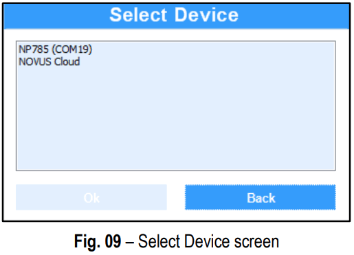
The first time you read a device, you must select the device to be connected. Simply double click on the desired device or, once it is selected, click on the Ok button. This device will be adopted as the default option for the next times the software performs the communication process.
8.3 CONFIGURING WITH NXPERIENCE
To configure the device, it must be connected to a USB port on the computer.
When clicking on the Configure button, the following screen is displayed:

The Create Configuration button creates a configuration from scratch, without needing the device. This configuration can be saved in a file for future use or can be recorded to a connected device.
The Open Configuration button reads a configuration file already created.
The Read Device button reads the current device configuration. When selecting this option, all features available for configuration will be displayed, as shown in the Fig. 11: 
![]() General: On this tab, the user can assign an identification name to the device and define the configuration parameters for the serial interface. Additionally, the device model, serial number, firmware version and the maximum and minimum pressure range of the sensor can be identified.
General: On this tab, the user can assign an identification name to the device and define the configuration parameters for the serial interface. Additionally, the device model, serial number, firmware version and the maximum and minimum pressure range of the sensor can be identified.![]() Input: On this tab, the user can select the system of measures to be used by the device, in addition to configuring the offset and digital filter for the pressure sensor input.
Input: On this tab, the user can select the system of measures to be used by the device, in addition to configuring the offset and digital filter for the pressure sensor input.![]() Output: On this tab, the user can configure the transmission analog output and the alarm output.
Output: On this tab, the user can configure the transmission analog output and the alarm output.![]() Diagnostics: On this tab, the user can check if the device is functioning properly by forcing the pressure readings and forcing the alarm output.
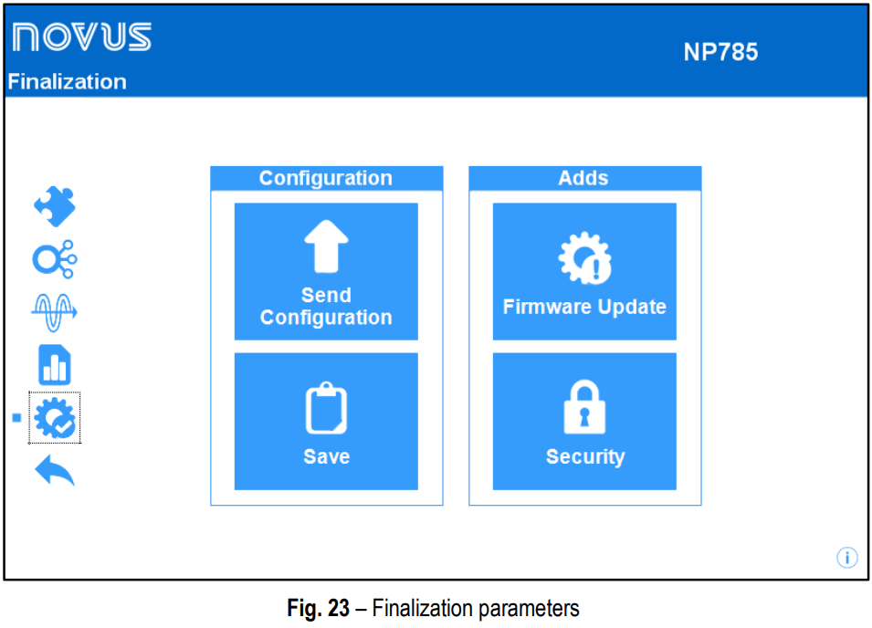
Diagnostics: On this tab, the user can check if the device is functioning properly by forcing the pressure readings and forcing the alarm output.![]() Finalization: On this tab, the user can send the configuration to the device, save the configurations in a file, update the device firmware and configure a password to protect the device.
Finalization: On this tab, the user can send the configuration to the device, save the configurations in a file, update the device firmware and configure a password to protect the device.![]() Back: Returns to NXperience home screen.
Back: Returns to NXperience home screen.
8.3.1 GENERAL PARAMETERS
By clicking on the ![]() icon, you can view information of the device being configured and the serial interface configuration parameters.
icon, you can view information of the device being configured and the serial interface configuration parameters.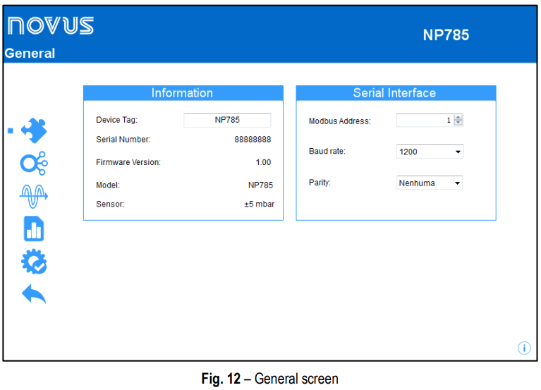
In the Device Tag parameter, you can name the device to be configured to make it easily identifiable within a multi-device network. Serial Number, Firmware Version, and Model are non-editable parameters that are read by the software and directly from the device.
In order for the NP785 Ultra Low Differential Pressure Transmitter to be recognized as a slave device in a Modbus network, you must assign a unique Modbus Address in the network and configure the Baud Rate and Parity.
8.3.2 INPUT PARAMETERS
By clicking on the![]() icon, you can configure the pressure sensor input.
icon, you can configure the pressure sensor input.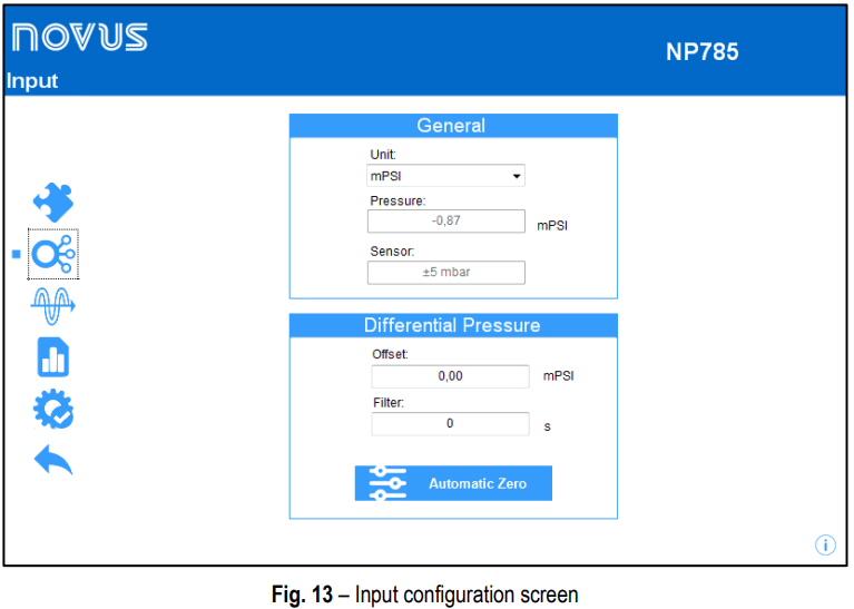
In the Unit parameter, you can select the units mbar, Mpsi, in H2O, mm H2O or pascal. By default, the unit of device is set to mbar.
The Pressure parameter informs the differential pressure of the device when the window opens.
The device also provides Offset and Filter adjustments, allowing not only small corrections to the sensor readings, but also to reduce the speed of response of the sensor.
The Automatic Zero configuration allows automatic offset adjustments. Make sure the pressure points are depressurized and click ![]() to make the adjustment.
to make the adjustment.
8.3.3 OUTPUT PARAMETERS
By clicking on the![]() icon, you can configure the transmission analog output and the alarm output.
icon, you can configure the transmission analog output and the alarm output.
8.3.3.1 TRANSMISSION OUTPUT CONFIGURATION
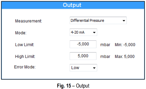
The Measurement parameter allows the differential pressure quantity reading.
The analog output Mode allows you to select the electrical standard to be used for the transmission: 0-10 V or 4-20 mA. The electrical signal of the output will be proportional to the selected magnitude, respecting the values configured in the Lower Limit and in the Upper Limit parameters.
In case of sensor failure, the quantity to be transmitted by the analog output will go into Error Mode. For the error condition, you must select the High, Low or Low-High state (check Table 03).
8.3.3.2 ALARM OUTPUT CONFIGURATION
To select the alarm output to be configured, you must click on the button ![]() and enable it by sliding the enable switch to the right.
and enable it by sliding the enable switch to the right.
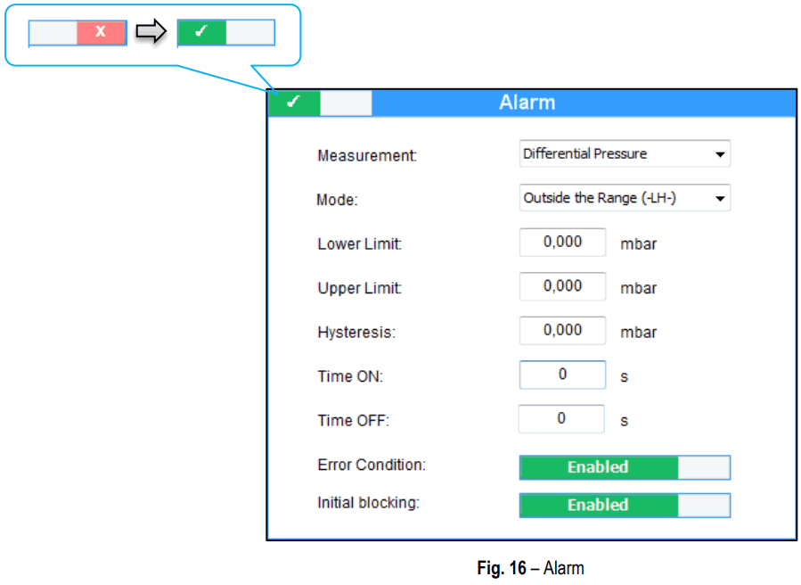
The alarm output may be timed by the Time On and Time Off parameters.
If the equipment is configured in the Value Lower than SPLo, Value Higher than SPHi, Inside the Range or Outside the Range modes, the Error Condition parameter allows you to configure a safe state of the alarm output in case of sensor failure. Thus, the output will be on or off depending on the value set in this parameter.
Upper Limit and Lower Limit are the differential pressure values that act as alarm activation conditions that, together with the Hysteresis, define the barrier to be exceeded so that the channel exits the alarm situation. For more information about the alarm configuration, check the Alarm Configuration section.
8.3.4 DIAGNOSTICS
To access this section, the device must be connected to the USB port and the Read Configuration option must be selected.
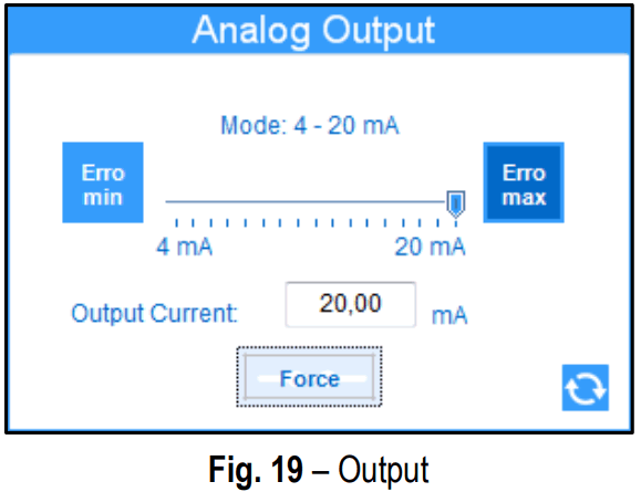
By clicking on the icon, you can check if the device is functioning properly by forcing the pressure readings. You can force a value either on the sensor reading or directly on the output.
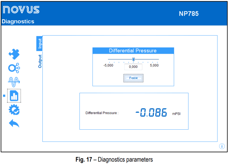
In the input diagnostics, you can view the differential pressure instantaneous value and force a value to it. To force a value, you must type the desired value in the field or run the slider to the desired value within the model pressure range and press the button.
In the output diagnostics, you can force the output in order to verify the correct operation of the device and test the settings applied to the NP785 Differential Pressure Transmitter.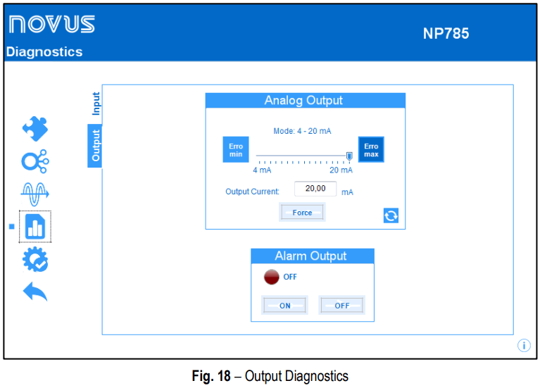
To force a value at a transmission analog output, use the slider or type de desired value directly into the edit field and then press the button![]() .
.
From this moment, the NP785 Ultra Low Differential Pressure Transmitter will force the adjusted value into the transmission output and the button used to perform the forcing will change to![]() . If pressed again, the forced value will no longer be applied to the output.
. If pressed again, the forced value will no longer be applied to the output.
 For each analogue output, it is also possible to force the transmission of an error value by clicking the
![]() and
and![]() buttons. These values depend on the mode (0-10 V or 4-20 mA) configured for each output.
buttons. These values depend on the mode (0-10 V or 4-20 mA) configured for each output.
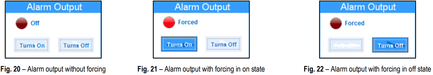
The alarm output allows forcing the condition on and off. In some cases, it is possible that an alarm output is activated due to an alarm condition.
Thus, it may be desirable to force the off state so that it is possible to identify any faults in the electrical installation or in the device configuration.
The images below shows the forcing interface of the alarm output in the three possible conditions: No forcing, forcing on ON and forcing in OFF state.
8.3.5 FINALIZATION
By clicking on the![]() icon, you can send the configuration to the device, save the configurations in a file, update the device firmware and configure a password to protect it.
icon, you can send the configuration to the device, save the configurations in a file, update the device firmware and configure a password to protect it.
TECHNICAL SPECIFICATION
| NP785-05 MODEL | NP785-20 MODEL | ||
| Measuring Range | -5 to 5 mbar | -20 to 20 mbar | |
| Burst Pressure | 200 mbar | 400 mbar | |
| Proof Pressure* | 100 mbar | 300 mbar | |
| Accuracy | 1 % of maximum range F.S.** | 1 % of maximum range F.S.** | |
|
Sensor Resolution (per unit) | 7.630E-4 mbar | 3.052E-3 mbar | |
| 1.107E-2 mpsi | 4.426E-2 mpsi | ||
| 3.063E-4 inH2O | 1.226E-3 inH2O | ||
| 7.780E-3 mmH2O | 3.112E-2 mmH2O | ||
| 7.630E-2 Pa | 3.052E-1 Pa | ||
| Granularity of Pressure Recorders (per unit) | 0.001 mbar | 0.001 mbar | |
| 0.01 mpsi | 0.01 mpsi | ||
| 0.001 inH2O | 0.001 inH2O | ||
| 0.01 mmH2O | 0.01 mmH2O | ||
| 0.1 Pa | 0.1 Pa | ||
| Start-Up Time | < 2 s | ||
| Operating Temperature | -5 to 65 °C | -20 to 85 °C | |
| Storage Temperature | -20 to 85 °C | ||
| Power Supply Voltage | · Power supply from PWR terminals: 12 Vdc to 30 Vdc; · USB cable power: 4.75 Vdc to 5.25 Vdc. Internal protection against reverse polarity of the supply voltage. | ||
| Power Supply Current | < 45 mA ± 10 % @ 24 Vdc | ||
| Input | Two sockets for the pneumatic hose connection of 4 or 6 mm internal diameter. | ||
| Output | They may be configured independently to operate with signals 0-10 V or 4-20 mA. · 0-10 V o Maximum current: 2 mA; o Resolution: 0.003 V. · 4-20 mA o Maximum load: 500 R; o Resolution: 0.006 mA. | ||
| Protection Rating | IP 20 | ||
| Housing | ABS + PC | ||
| Electromagnetic Compatibility | EN/IEC 61326-1 | ||
| NXperience | 10, 8 / 8.1 (32 and 64 bits), 7, Vista and XP. configurator software. Menus in Portuguese, Spanish, French and English. | ||
| Certifications | CE MARK This is a Class A product. In a domestic environment, this product may cause radio interference in which case the user may be required to take adequate measures. | ||
* Proof Pressure is defined as the maximum pressure at which the device can be subjected and which still maintains its performance within specifications after returning to the operating range.
** F.S .: Full scale at 25 °C.
Table 12 – Technical Specifications
WARRANTY
Warranty conditions are available on our website www.novusautomation.com/warranty.
![]()


