Dwyer 636 Series Fixed Range Pressure Transmitter Instruction Manual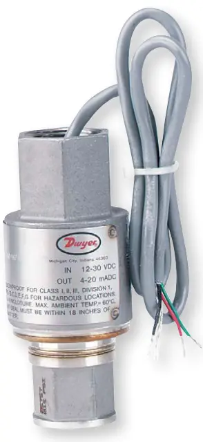
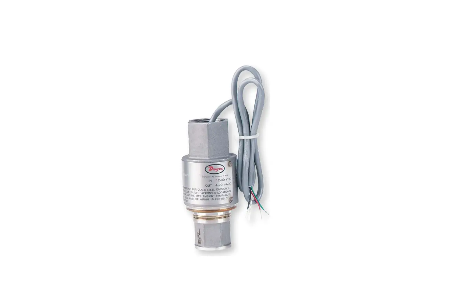
The Series 636 Fixed Range Pressure Transmitter converts liquid, gas or vapor pressure into a 4-20 mA DC or 1-5 VDC (636LP) output signal. All 316 stainless steel construction makes it compatible with most corrosive media. This explosion proof control is FM approved for use in hazardous locations and it meets NACE Standards for offshore applications. It is also weatherproof, capable of resisting a direct water spray. With these quality features and ±0.3% full-scale accuracy, the Series 636 is an exceptional value.
The design is based on a sensitive piezoresistive sensing element consisting of four diffused strain gages. They form a bridge circuit which varies its resistance when stressed by the process pressure. Small size and light weight eliminate the need for complicated mounting hardware and mechanical supports. With simple in-line wiring, installation is quick and inexpensive. Slim profile enables mounting in spaces too tight for many other transmitters.
MODEL CHART | |||
| Model | Output | Operating Range, psi | Operating Range, bar |
| 636-0 | 4-20 mA | 0 to 15 | 0 to 1 |
| 636-1 | 4-20 mA | 0 to 30 | 0 to 2 |
| 636-2 | 4-20 mA | 0 to 100 | 0 to 7 |
| 636-3 | 4-20 mA | 0 to 300 | 0 to 20 |
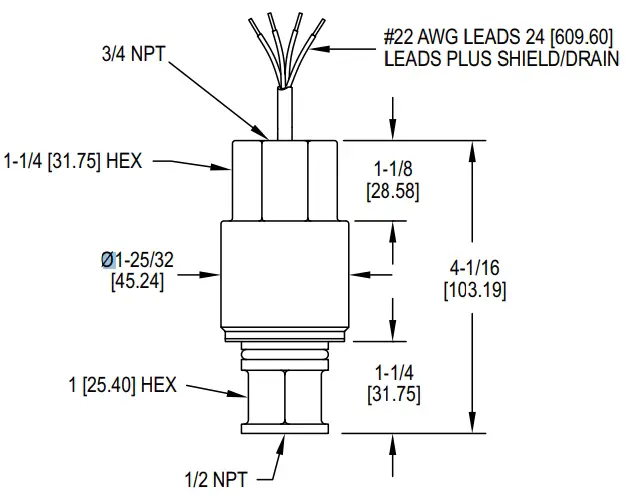
Figure 1
SPECIFICATIONS
- Service: Liquid, gas or vapor.
- Wetted Materials: 316L SS.
- Fill Fluid: DC 200 silicone (standard).
- Accuracy: ±0.30% of calibrated span including linearity hysteresis and repeatability (BFSL) at 25°C (77°F) and 12 VDC excitation.
- Stability: ±0.5% of upper range limit for six months.
- Temperature Limits: Electronics (ambient): -40 to 140°F (-40 to 60°C);
- Process interface: -40 to 212°F (-40 to 100°C).
- Pressure Limits: 300% upper range limit.
- Compensated Temperature Range: -20 to 180°F (-29 to 82°C).
- Thermal Effect: (includes zero and span). Between -20 and 180°F (-29 and 82°C). ±2.0% per 50°F (28°C).
- Power Requirements: 12-30 VDC (636), 8-14 VDC (636LP), reverse polarity protection.
- Output Signal: 4-20 mA DC, limited to 30 mA DC (636), 1-5 VDC (636LP).
- Zero and Span Adjustments: Null: 4.0 mA ±2% span (636),1 VDC ±1% span (636LP); Span: 16.0 mA ±1% span (636), 4 VDC ±1% span (636LP).
- Loop Resistance: 900 Ω max @ 30 V.
- Electrical Connection: 3/4˝ female NPT 24˝ (61 cm), 22 AWG.
- Process Connection: 1/2˝ female NPT.
- Enclosure Rating: NEMA 4 (IP56).
- Weight: 0.83 Ib (374 g).
- Compliance: CSA, FM.
FM and CSA approved explosion-proof for Class I, Division 1, Groups B, C, and D, Class II Groups E, F, and G Class III.
INSTALLATION
Care should be taken during installation to prevent condensate accumulation in the conduit compartment or sediment accumulation in the diaphragm chamber. See Figure 2 for suggested piping arrangements in several typical situations. Use pipe joint compound or Teflon® thread tape to assure a leak-proof process connection.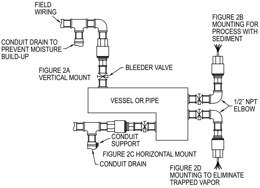
Figure 2
ELECTRICAL CONNECTIONS
CAUTION
Do not exceed specified supply voltage rating. Permanent damage not covered by warranty will result. This unit is not designed for AC line voltage operation. Power must be off while wiring connections are being made.
An external power supply delivering 12-30 VDC with a minimum current capability of 40 mA DC (per transmitter) or 8-14 VDC if using model 636LP, must be used to power the control loop. See Figure 3.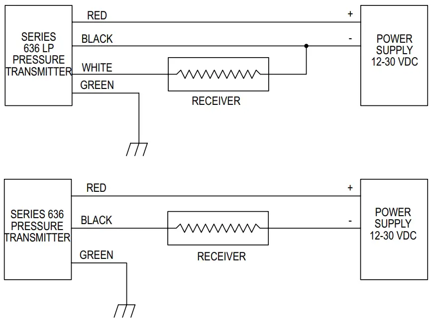
Figure 3
To comply with good electrical practice, it is recommended that the transmitter be grounded. This can be accomplished through either the green wire or the transmitter case. To avoid a “ground loop” condition, DO NOT use both. The shield/drain wire is not connected to the case. This shield/drain is normally tired to ground at the receiver for optimal noise rejection.
The range of appropriate loop resistance, including the receiver load resistance for the DC power supply being used is limited to that expressed by the graph in Figure 4.
Loop Resistance: 900 Ω max. @ 30 V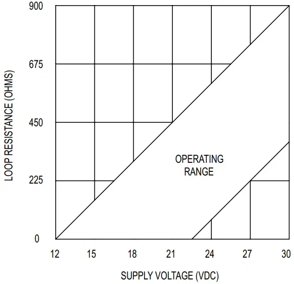
Figure 4
MAINTENANCE
After final installation of the Series 636 Fixed Range Pressure Transmitter, no routine maintenance is necessary. These transmitters are not field serviceable and should be returned to the factory, freight prepaid, if repair is needed. Be sure to include a clear description of the problem plus any applications information available.
Support
©Copyright 2021 Dwyer Instruments, Inc.
P.O. BOX 373
MICHIGAN CITY, INDIANA 46360, U.S.A.
Phone: 219-879-8000
Fax: 219-872-9057
www.dwyer-inst.com
e-mail: [email protected]