
Dwyer P-626-CB-1 Series 626 628-CB Industrial Pressure Transmitters
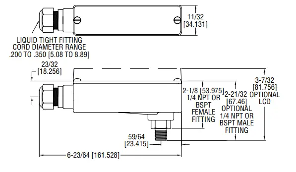
DIMENSION
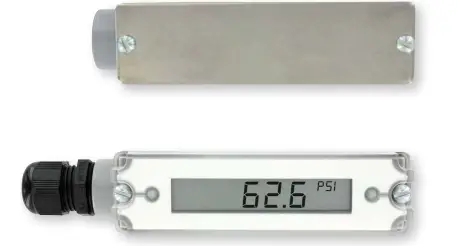
The Series 626 and 628 Pressure Transmitters monitor the pressure of compatible gases and liquids with 0.25% full-scale accuracy for 626 models or 1.0% full-scale accuracy for 628 models. The design employs a pressure sensor that can convert a single positive pressure into a standard 4-20 mA output. The Series 626 and 628 are designed to meet NEMA 4X (IP66) construction.
| PRESSURE LIMITS | ||
| Range | *Maximum Pressure | Over Pressure |
| 0 to 5 psi | 10 psi | 50 psi |
| 0 to 15 psi | 30 psi | 150 psi |
| 0 to 30 psi | 60 psi | 300 psi |
| 0 to 50 psi | 100 psi | 300 psi |
| 0 to 100 psi | 200 psi | 500 psi |
| 0 to 150 psi | 300 psi | 750 psi |
| 0 to 200 psi | 400 psi | 1000 psi |
| 0 to 300 psi | 600 psi | 1500 psi |
| 0 to 500 psi | 1000 psi | 2500 psi |
| 0 to 600 psi | 1200 psi | 3000 psi |
| 0 to 1000 psi | 2000 psi | 5000 psi |
| 0 to 1500 psi | 3000 psi | 5000 psi |
| 0 to 3000 psi | 6000 psi | 7500 psi |
| 0 to 5000 psi | 7500 psi | 10000 psi |
| 0 to 8000 psi | 10000 psi | 12000 psi |
| Pressures exceeding the maximum pressure limit may cause a calibration shift of up to ±3% of full-scale. | ||
SPECIFICATIONS
- Service: Compatible gases and liquids.
- Wetted Materials: Type 316 SS.
- Accuracy: 626: 0.25% FS, 0.20% RSS; 628: 1.0% FS, 0.5% RSS; 626 absolute
- ranges: 0.5% FS, 0.35% RSS (includes linearity, hysteresis, and repeatability).
- Temperature Limits: 0 to 200°F (-18 to 93°C).
- Compensated Temperature Limits: 0 to 175°F (-18 to 79°C).
- Pressure Limits: See chart.
- Thermal Effect: 626: ±0.02% FS/°F; 628: ±0.04% FS/°F (includes zero and span).
- Power Requirements: 2-wire: 10-30 VDC.
- Output Signal: 2-wire: 4-20 mA.
- Response Time: 300 msec.
- Loop Resistance: Current output: 0 to 1000 Ω (max), Rmax = 50(Vps-10).
- Current Consumption: 38 mA (max).
- Electrical Connections: Quick connect wire joints. 1/2˝ female NPT conduit.
- Process Connections: 1/4˝ female or male NPT.
- Enclosure Rating: Designed to meet NEMA 4X (IP66) for non-LCD models.
- Mounting Orientation: Not position sensitive.
- Weight: 10 oz (283 g).
- Compliance: CE.
INSTALLATION
- Location: Select a location where the temperature of the unit will be between 0 and 175°F (-18 to 79°C). Distance from the receiver is limited only by total loop resistance. The tubing feeding pressure to the instrument can be practically any length required, but long lengths will increase response time slightly.
- Position: The transmitter is not position-sensitive. However, all standard models are originally calibrated with the unit in a position with the pressure connection downward. Although they can be used at other angles, for best accuracy, it is recommended that units be installed in the position calibrated at the factory.
- Pressure Connection: Use a small amount of plumber’s tape or other suitable sealants to prevent leaks. Be sure the pressure passage inside the port is not blocked.
- Electrical Connections: Wire Length – The maximum length of wire connecting the transmitter and receiver is a function of wire size and receiver resistance. Wiring should not contribute to more than 10% of the receiver resistance to total loop resistance. For extremely long runs (over 1000 ft or 305 m), choose receivers with higher resistance to minimize the size and cost of connecting leads. Where the wiring length is under 100 feet (30.5 m), wire as small as 22 AWG can be used.
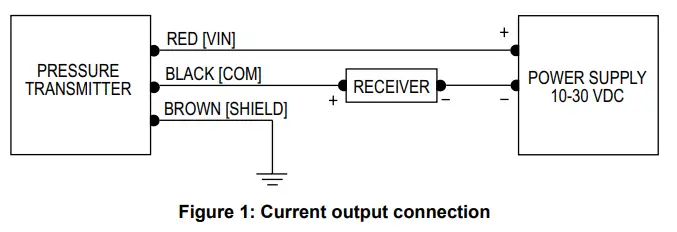
CURRENT (4-20 mA) OUTPUT OPERATION
An external power supply delivering 10-30 VDC with a minimum current capability of 40 mA DC (per transmitter) is required to power the control loop. See Figure 1 for the connection of the power supply, transmitter, and receiver. The range of appropriate receiver load resistance (RL) for the DC power supply voltage available is expressed by the formula:
- RL Max = Vps – 10
- 20 mA DC
A shielded cable is recommended for control loop wiring.
Electrical connections to the Series 626/628-CB pressure transmitters are made to the terminal block located inside the housing. Remove the screws and lift off the cover. Lift off the terminal block for wiring. The wire is shown in Figure 1. Use Figure 1 for the current output connection. If ordering pre-wired cable, black wire is negative [-] and red wire is positive [+].
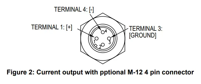
M-12 Pin Connector with Current Output
For the optional M-12 4 pin connector, wire to pins as shown in Figure 2.
| MODEL CHART | ||||||||
| Example | 626 | -02 | -CB | -P1 | -E2 | -S8 | -NIST | 626-02-CB-P1-E2-S8-NIST |
| Series | 626 628 | 0.25% FS accuracy 1.0% FS accuracy | ||||||
| Range | 06 07 08 09 10 11 12 13 14 22 15 16 18 19 26 | 0 to 5 psi 0 to 15 psi 0 to 30 psi 0 to 50 psi 0 to 100 psi 0 to 150 psi 0 to 200 psi 0 to 300 psi 0 to 500 psi 0 to 600 psi 0 to 1000 psi 0 to 1500 psi 0 to 3000 psi 0 to 5000 psi 0 to 8000 psi | ||||||
| Housing | CB | Conduit box housing | ||||||
| Process Connection | P1 P2 P3 P4 | 1/4˝ male NPT 1/4˝ female NPT 1/4˝ male BSPT 1/4˝ female BSPT | ||||||
| Electrical Connection | E1 E2 E3 E5 E9 | Cable gland with 3´ prewired cable Cable gland with 6´ prewired cable Cable gland with 9´ prewired cable 1/2˝ female NPT conduit M-12 4 pin connector (not UL) | ||||||
| Signal Output | S1 S8 | 4 to 20 mA Selectable 0-5, 1-5, 0-10, or 2-0 VDC | ||||||
| Options | AT LCD NIST
SPCL | Aluminum tag LCD display NIST traceable calibration certificate Special cleaning for oxygen use | ||||||
| Note: Pressures exceeding the working pressure limit may cause a calibration shift of up to ±3% of full-scale. | ||||||||
MAINTENANCE/REPAIR
Upon final installation of the Series 626/628-CB Industrial Pressure Transmitter, no routine maintenance is required. The Series 626/628-CB is not fielded serviceable and is not possible to repair the unit. Field repair should not be attempted and may void the warranty.
WARRANTY/RETURN
Refer to “Terms and Conditions of Sale” in our catalog and on our website. Contact customer service to receive a Return Goods Authorization number before shipping the product back for repair. Be sure to include a brief description of the problem plus any additional application notes.
©Copyright 2022 Dwyer Instruments, Inc.
DWYER INSTRUMENTS, INC.
- ADDRESS: P.O. BOX 373 MICHIGAN CITY, INDIANA 46360, U.S.A.
- Phone: 219-879-8000
- Fax: 219-872-9057
- www.dwyer-inst.com
- e-mail: [email protected]


