PPI neuro 202 Enhanced Universal Single Loop Process Controller User Manual
| INPUT/OUTPUT CONFIGURATION PARAMETERS : PAGE 12 | ||
Parameters | Settings (Default Value) | |
Control Action | 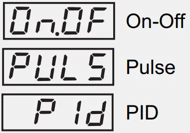 | |
Control Logic | (Default : Reverse)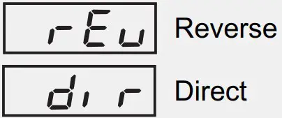 | |
Setpoint Low Limit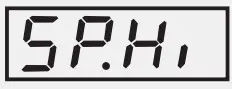 | Min. Range to Setpoint High for the selected Input Type (Default : -199) | |
Setpoint High Limit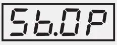 | Setpoint Low to Max. Range for the selected Input Type (Default : 1376) | |
Sensor Break Output Power % | 0 to 100(Default : 0) | |
Input Type | Refer Table 1 (Default : Type K) | |
| PV Units | °C°F(Default : °C)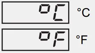 | |
| Signal Low | Input Type Settings Default0 to 20 mA 0.00 to Signal High 0.004 to 20 mA 4.00 to Signal High 4.00Reserved 0.0 to Signal High 0.00 to 80 mV 0.00 to Signal High 0.000 to 1.25 V 0.000 to Signal High 0.0000 to 5 V 0.000 to Signal High 0.0000 to 10 V 0.00 to Signal High 0.001 to 5 V 1.000 to Signal High 1.000 | |
| Signal High | Input Type Settings Default0 to 20 mA Signal Low to 20.00 20.004 to 20 mA Signal Low to 20.00 20.00Reserved Signal Low to 80.00 80.000 to 80 mV Signal Low to 80.00 80.000 to 1.25 V Signal Low to 1.250 1.2500 to 5 V Signal Low to 5.000 5.0000 to 10 V Signal Low to 10.00 10.001 to 5 V Signal Low to 5.000 5.000 | |
PV Resolution | Refer Table 1(Default : 1) | |
PV Range Low} | -1999 to 9999(Default : 0) | |
PV Range High | -1999 to 9999(Default : 1000) | |
| Offset for PV | For DC mA/mV/V :1 to 9999 counts For Thermocouples/RTD : 1 to 999 or 0.1 to 999.9(Default : 0) | |
Digital Filter Time Constant | 0.5 to 60.0 Seconds (in steps of 0.5 Seconds)(Default : 2.0 Sec.) | |
CONTROL PARAMETERS : PAGE 10
| Parameters | Settings (Default Value) |
Proportional Band | 1 to 9999 counts (Default : 500) |
Integral Time | 0 to 3600 Seconds (Default : 100 Sec.) |
Derivative Time | 0 to 600 Seconds (Default : 16 Sec.) |
Cycle Time | 0.5 to 100.0 Seconds (in steps of 0.5 secs.) |
Relative Cool Gain | 0.1 to 10.0 (Default : 1.0) |
Cool Cycle Time | 0.5 to 100.0 Seconds (in steps of 0.5 secs.) (Default : 10.0 sec.) |
Hysteresis | 1 to 9999 counts (Default : 2) |
Pulse Time} | Pulse ON Time to 120.0 Seconds (Default : 2.0 sec.) |
Pulse On Tim | 0.1 to Value set for Pulse Time (Default : 1.0) |
Cool Hysteresis | 1 to 9999 counts (Default : 2) |
Cool Pulse Time | Cool ON Time to 120.0 Seconds (Default : 2.0) |
Cool Pulse ON Time | 0.1 to Value set for Cool Pulse Time (Default : 1.0) |
Heat Power Low | 0 to Heat Power High (Default : 0 |
Heat Power High | Heat Power Low to 100 (Default : 100) |
Cool Power Low | 0 to Cool Power High (Default : 0) |
Cool Power High | Cool Power Low to 100 (Default : 100) |
SUPERVISORY PARAMETERS : PAGE 13
| Parameters | Settings (Default Value |
Self-Tune Command | (Default : No) |
Overshoot Inhibi | (Default : Disable) |
Overshoot Inhibit Facto | 1.0 to 2.0 (Default : 1.0) |
SP Adjustment on Lower Readout | (Default : Enable) |
SP Adjustment on Operator Page | (Default : Enable) |
Manual Mode | (Default : Disable)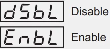 |
Alarm SP Adjustment on Operator Page | (Default : Disable)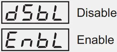 |
Standby Mode | (Default : Disable)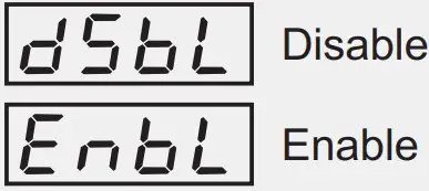 |
Profile Abort Command on Page-1 | (Default : Disable)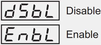 |
Controller ID Number | 1 to 127 (Default : 1) |
Baud Rate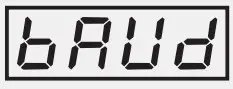 | (Default : 9.6)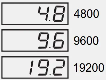 |
Communication Parity | (Default : Even)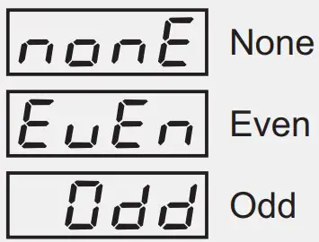 |
Communication Write Enable | (Default : Yes)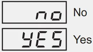 |
OP1, OP2 & OP3 FUNCTION PARAMETERS : PAGE 15
| Parameters | Settings (Default Value) |
Output-1 Type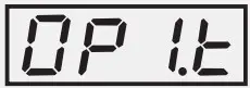 | (Default : Relay)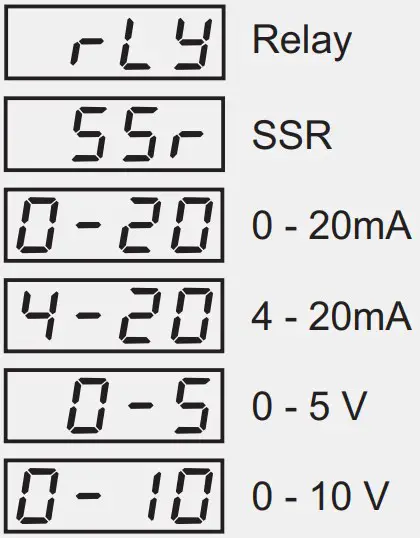 |
Output-2 Function Selection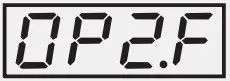 | (Default : None)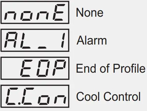 |
Alarm-1 Logic | (Default : Normal |
Output-2 Type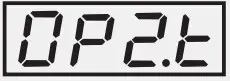 | (Default : Relay)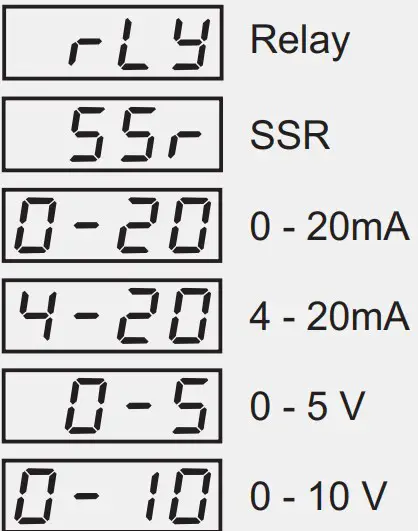 |
OP2 Event Status | (Default : ON)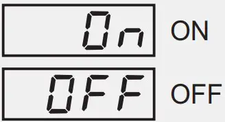 |
OP2 Event Time Units | (Default : Seconds)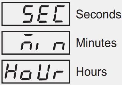 |
OP2 Event Time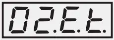 | 0 to 9999 (Default : 0) |
Output-3 Function Selection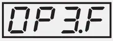 | (Default : Alarm)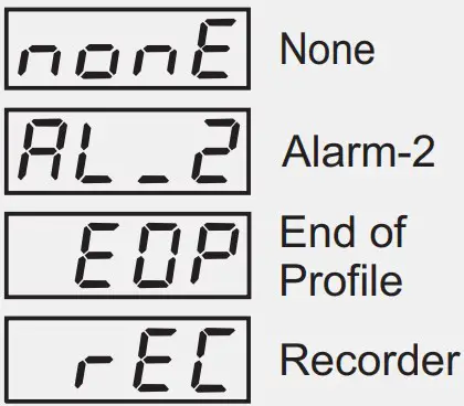 |
Alarm-2 Logic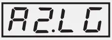 | (Default : Normal)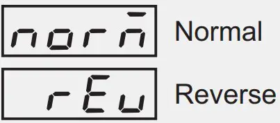 |
OP3 Event Status | (Default : ON)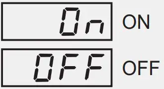 |
OP3 Event Time Units | (Default : Seconds)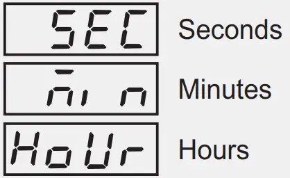 |
OP3 Event Time | (Default : 0) 0 to 9999 |
Recorder Output Typ | (Default : 0 to 20mA)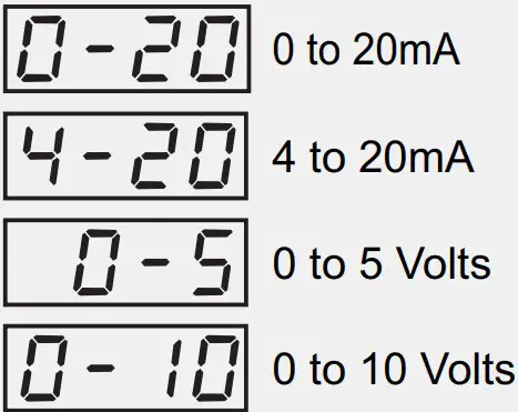 |
| ALARM AND RETRANSMISSION (RECORDER) PARAMETERS : PAGE 11 | |
| Parameters | Settings (Default Value) |
| Alarm-1 Type
| 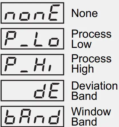 |
| Alarm-1 Setpoint | Min. to Max. Range specified for the selected Input Type (Default : Min or Max Range) |
| Alarm-1 Deviation Band
| For DC mA/mV/V : -1999 to 9999 counts For Thermocouples/RTD : -999 to 999 or -1.999 to 999.9 (Default : 5) |
| Alarm-1 Window Band | For DC mA/mV/V : 3 to 9999 counts For Thermocouples/RTD : 3 to 999 or 0.3 to 999.9 (Default : 5) |
| Alarm-1 Hysteresis | For DC mA/mV/V : 1 to 9999 counts For Thermocouples/RTD : 1 to 999 or 0.1 to 999.9 (Default : 2) |
| Alarm-1 Inhibit | (Default : No) 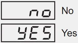 |
Alarm-2 Type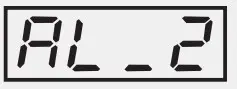 | 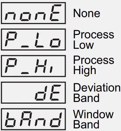 |
| ON-LINE ALTERATIONS : PAGE 1 | |
| Parameters | Settings (Default Value) |
End of Profile Acknowledge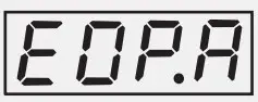 |  |
Profile Start Command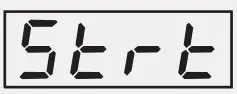 |  |
Profile Abort Command | |
Profile Pause Command |  |
Segment Skip Command | No Yes(Default : No) |
Segment Time Interval | 0 to 9999 Minutes |
Segment Holdback Type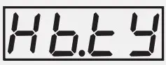 | None |
| Up | |
| Down | |
| Both | |
Segment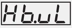 | For DC mA/mV/V : |
| Band Value | 1 to 9999 counts |
| For Thermocouples/RTD :1 to 999 or 0.1 to 999.9 | |
Profile Repeat Counter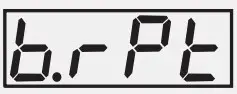 | 1 to 9999 |
| Option | What it means | Range (Min. to Max.) | Resolution |
| Type J Thermocouple | 0 to +960°C / +32 to +1760°F | Fixed 1°C / 1°F | |
| Type K Thermocouple | -200 to +1376°C / -328 to +2508°F | ||
| Type T Thermocouple | -200 to +385°C / -328 to +725°F | ||
| Type R Thermocouple | 0 to +1770°C / +32 to +3218°F | ||
| Type S Thermocouple | 0 to +1765°C / +32 to +3209°F | ||
| Type B Thermocouple | 0 to +1825°C / +32 to +3092°F | ||
| Type N Thermocouple | 0 to +1300°C / +32 to +2372°F | ||
| Reserved for customer specific Thermocouple type not listed above. The type shall be specified in accordance with the ordered (optional on request) Thermocouple type. | |||
| 3-wire, RTD Pt100 | -199 to +600°C / -328 to +1112°For–199.9 to 600.0°C / -199.9 to 999.9°F | User settable 1°C / 1°For0.1°C / 0.1°F | |
| 0 to 20mA DC current | -1999 to +9999 units | User settable 1 / 0.1 / 0.01/0.001 units | |
| 4 to 20mA DC current | |||
| Reserved | |||
| 0 to 80mV DC voltage | |||
| 0 to 1.25V DC voltage | |||
| 0 to 5.0V DC voltage | |||
| 0 to 10.0V DC voltage | |||
| 1 to 5.0V DC voltage | |||
FRONT PANEL LAYOUT
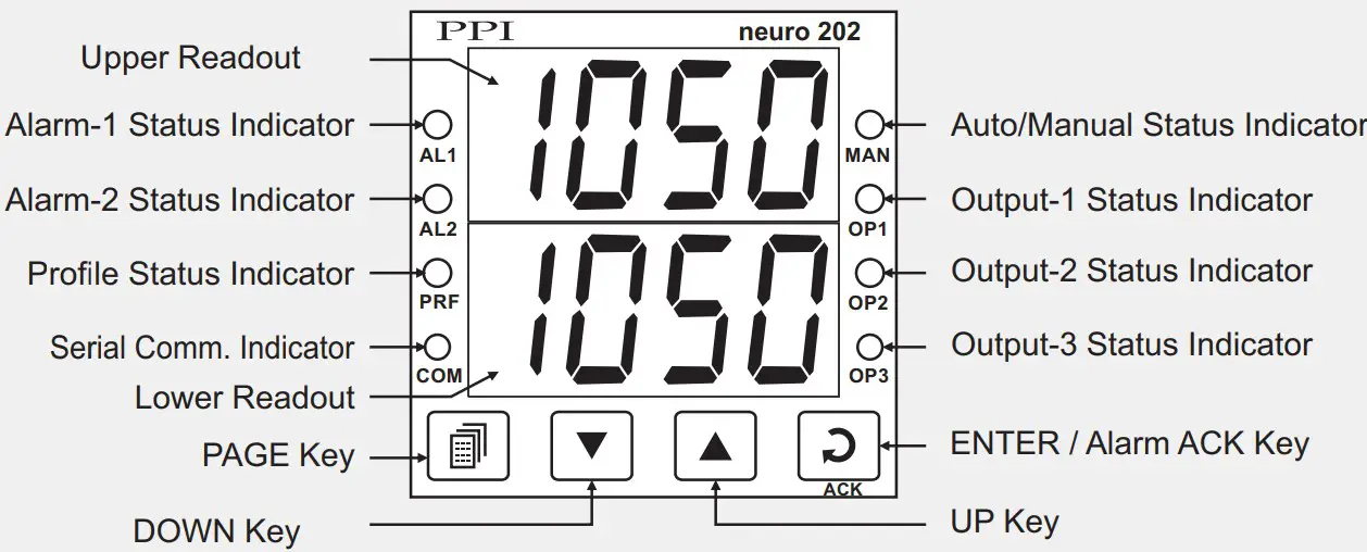
| Symbol | Key | Function |
| PAGE | Press to enter or exit set-up mode. | |
| DOWN | Press to decrease the parameter value. Pressing once decreases the value by one count; keeping pressed speeds up the change. | |
| UP | Press to increase the parameter value. Pressing once increases the value by one count; keeping pressed speeds up the change. | |
| ENTER / ACK | Set up Mode : Press to store the set parameter value and to scroll to the next parameter on the PAGE.Run Mode : Press to acknowledge any pending Alarm(s).This also turns off the Alarm relay. |
| Message | PV Error Type |
| Over-range(PV above Max. Range) | |
| Under-range(PV below Min. Range) | |
| Open(Sensor open / broken) |
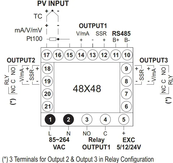
ELECTRICAL CONNECTIONS