![]() INSTALLATION MANUAL
INSTALLATION MANUAL
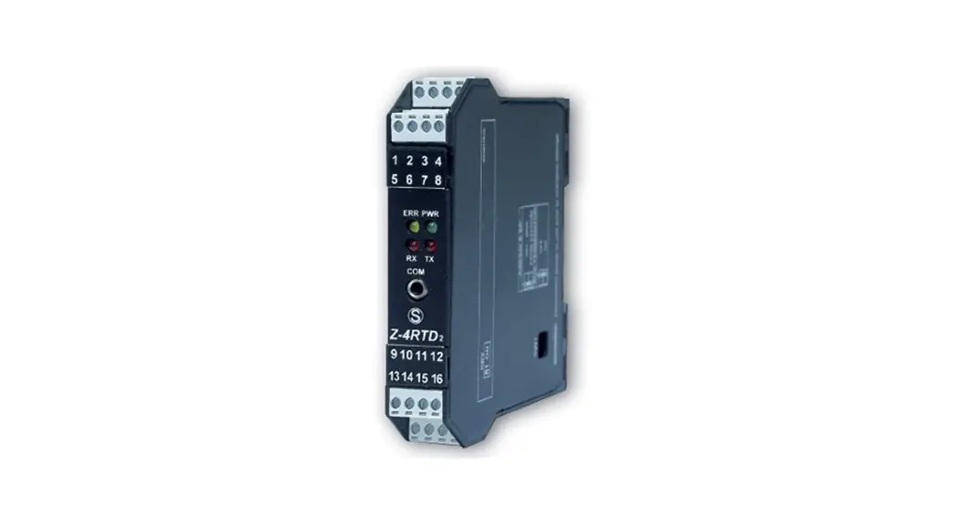
Z-4RTD2-SI
PRELIMINARY WARNINGS
The word WARNING preceded by the symbol indicates conditions or actions that put the user’s safety at risk. The word ATTENTION preceded by the symbol indicates conditions or actions that might damage the instrument or the connected equipment. The warranty shall become null and void in the event of improper use or tampering with the module or devices supplied by the manufacturer as necessary for its correct operation, and if the instructions contained in this manual are not followed.
 | WARNING: The full content of this manual must be read before any operation. The module must only be used by qualified electricians. Specific documentation is available via QR-CODE shown on page 1. |
| The module must be repaired and damaged parts replaced by the Manufacturer. The product is sensitive to electrostatic discharges. Take appropriate measures during any operation. | |
 | Electrical and electronic waste disposal (applicable in the European Union and other countries with recycling). The symbol on the product or its packaging shows the product must be surrendered to a collection center authorized to recycle electrical and electronic waste. |
 https://www.seneca.it/products/z-4rtd2-si
DOCUMENTATION Z-4RTD2-SI![]()
SENECA s.r.l.; Via Austria, 26 – 35127 – PADOVA – ITALY; Tel. +39.049.8705359 – Fax +39.049.8706287
CONTACT INFORMATION
| Technical support | [email protected] | Product information | [email protected] |
This document is the property of SENECA srl. Copies and reproduction are prohibited unless authorized.
The content of this document corresponds to the described products and technologies.
Stated data may be modified or supplemented for technical and/or sales purposes.
MODULE LAYOUT
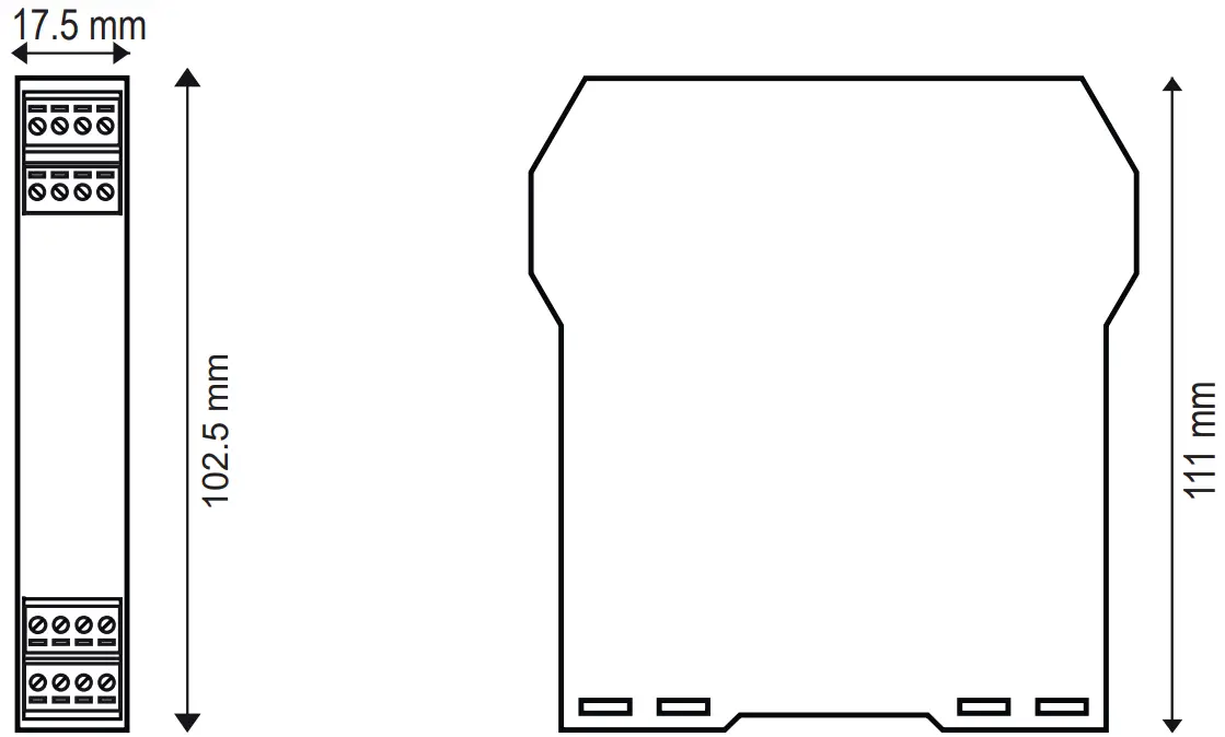
Dimensions: 17.5 x 102.5 x 111 mm
Weight: 100 g
Container: PA6, black
SIGNALS VIA LED ON FRONT PANEL
| LED | STATUS | LED meaning |
| PWR | ON | The device is powered correctly |
| FAIL | ON | Instrument in error state |
| RX | Flashing | Data receipt on port #1 RS485 |
| TX | Flashing | Data transmission on port #1 RS485 |
TECHNICAL SPECIFICATIONS
| CERTIFICATIONS |   https://www.seneca.it/products/z-4rtd2-si/doc/CE_declaration |
| POWER SUPPLY | 10 ÷ 40Vdc; 19 ÷ 28Vac; 50-60Hz; Max 0.8W |
| ENVIRONMENTAL CONDITIONS | Operating temperature: -25°C ÷ +70°C Humidity: 30% ÷ 90% non condensing Storage temperature: -30°C ÷ +85°C Altitude: Up to 2000 m above sea level Protection rating: IP20 |
| ASSEMBLY | 35mm DIN rail IEC EN60715 |
| CONNECTIONS | Removable 3.5 mm pitch terminal block, 1.5 mm2 max cable section |
| COMMUNICATION PORTS | 4-way removable screw terminal block; max. section 1.5mmTION 2 ; step: 3.5 mm IDC10 rear connector for IEC EN 60715 DIN bar, Modbus-RTU, 200÷115200 Baud Micro USB on the front, Modbus protocol, 2400 Baud |
| INSULATION | 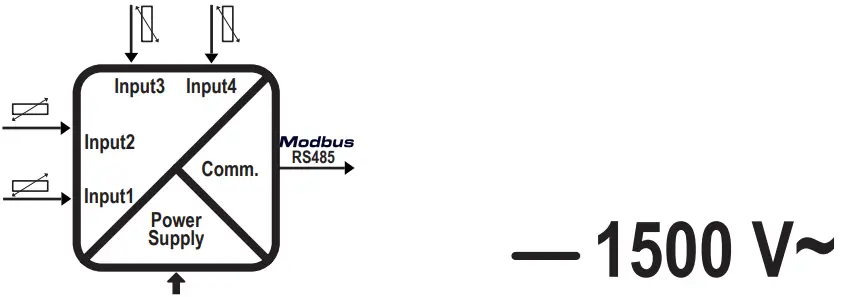 |
| ADC | Resolution: 24 bit Calibration precision 0.04% of full scale Class / Prec. Base: 0.05 Temperature drift: < 50 ppm/K Linearity: 0,025% of full scale |
N.B.: A delayed fuse with a maximum rating of 2.5 A must be installed in series with the power supply connection, near the module.
SETTING THE DIP-SWITCHES
The position of the DIP-switches defines the Modbus communication parameters of the module: Address and Baud Rate
The following table shows the values of the Baud Rate and the Address according to the setting of the DIP switches:
| DIP-Switch status | |||||
| SW1 POSITION | BAUD | SW1 POSITION | ADDRESS | POSITION | TERMINATOR |
| 1 2 3 4 5 6 7 8 | 3 4 5 6 7 8 | 10 | |||
| 9600 | #1 | Disabled | |||
| 19200 | #2 | Enabled | |||
| 38400 | • • • • • • • • • | #… | |||
| 57600 | #63 | ||||
| From EEPROM | From EEPROM | ||||
Note: When DIP – switches 1 to 8 are OFF, the communication settings are taken from programming (EEPROM).
Note 2: The RS485 line must be terminated only at the ends of the communication line.
| FACTORY SETTINGS | |||||||
| 1 | 2 | 3 | 4 | 5 | 6 | 7 | 8 |
| LEGEND | |
| ON | |
| OFF | |
The position of the dip-switches defines the communication parameters of the module.
The default configuration is as follows: Address 1, 38400, no parity, 1 stop bit.
| CH1 | CH2 | CH3 | CH4 | |
| Sensor Type | PT100 | PT100 | PT100 | PT100 |
| Type of data returned, measured in: | °C | °C | °C | °C |
| Connection | 2/4 WIRES | 2/4 WIRES | 2/4 WIRES | 2/4 WIRES |
| Acquisition rate | 100ms | 100ms | 100ms | 100ms |
| LED signal of channel failure | YES | YES | YES | YES |
| The value loaded in case of fault | 850 °C | 850 °C | 850 °C | 850 °C |
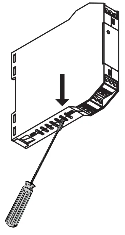
FIRMWARE UPDATE
Firmware update procedure:
- Disconnect the device from the power supply;
- Holding down the firmware update button (positioned as shown in the figure on the side), reconnect the device to the power supply;
- Now the instrument is in update mode, connect the USB cable to the PC;
- The device will be displayed as an “RP1-RP2” external unit;
- Copy the new firmware into the “RP1-RP2” unit;
- Once the firmware file has been copied, the device will automatically reboot.
INSTALLATION REGULATIONS
The module has been designed for vertical installation on a DIN 46277 rail. For optimal operation and long life, adequate ventilation must be provided. Avoid positioning ducting or other objects that obstruct the ventilation slots. Avoid mounting modules over heat-generating equipment. Installation in the bottom part of the electrical panel is recommended.
ATTENTION These are open-type devices and intended for installation in an end enclosure/panel offering mechanical protection and protection against spread of fire.
ELECTRICAL CONNECTIONS
CAUTION
To meet the electromagnetic immunity requirements:
– use shielded signal cables;
– connect the shield to a preferential instrumentation earth system;
– separate shielded cables from other cables used for power installations (transformers, inverters, motors, etc…).
ATTENTION
Use only copper or copper-clad aluminum or AL-CU or CU-AL conductors
Power supply and Modbus interface are available using the Seneca DIN rail bus, via the IDC10 rear connector, or the Z-PC-DINAL2-17.5 accessory.
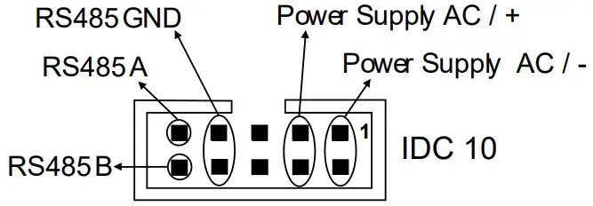
Rear Connector (IDC 10)
The illustration shows the meanings of the various IDC10 connector pins if signals are to be sent via them directly.
INPUTS:
the module accepts temperature probes with 2, 3, and 4 wire connections.
For the electrical connections: screened cables are recommended.
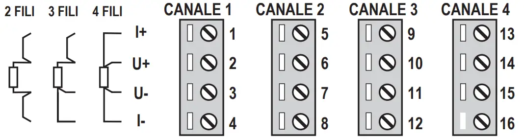
| 2 WIRES | This connection can be used for short distances (< 10 m) between module and probe. This connection introduces a measurement error equal to the resistance of the connection cables. |
| 3 WIRES | A connection to be used for medium distances (> 10 m) between module and probe. The instrument performs the compensation on the average value of the resistance of the connection cables. To ensure correct compensation, the cables must have the same resistance. |
| 4 WIRES | A connection to be used for long distances (> 10 m) between module and probe. It offers maximum precision, in view of the fact that the instrument reads the resistance of the sensor independently of the resistance of the cables. |
| INPUT PT100EN 607511A2 (ITS-90) | INPUT PT500 EN 607511A2 (ITS-90) | ||
| MEASURING RANGE | I -200 = +650°C | MEASURING RANGE | I -200 + +750°C |
| INPUT PT1000 EN 60751/A2 (ITS-90) | INPUT NI100 DIN 43760 | ||
| MEASURING RANGE | -200 + +210°C | MEASURING RANGE | -60 + +250°C |
| INPUT CU50 GOST 6651-2009 | INPUT CU100 GOST 6651-2009 | ||
| MEASURING RANGE | I -180 + +200°C | MEASURING RANGE | I -180 + +200°C |
| INPUT Ni120 DIN 43760 | INPUT NI1000 DIN 43760 | ||
| MEASURING RANGE | I -60 + +250°C | MEASURING RANGE | I -60 + +250°C |
MI00581-0-EN
INSTALLATION MANUAL


