
SENECA R-8AI-8DIDO IO module analog inputs 8 digital

PRELIMINARY WARNINGS
The word WARNING preceded by the symbol indicates conditions or actions that put the user’s safety at risk. The word ATTENTION preceded by the symbol indicates conditions or actions that might damage the instrument or the connected equipment. The warranty shall become null and void in the event of improper use or tampering with the module or devices supplied by the manufacturer as necessary for its correct operation, and if the instructions contained in this manual are not followed.
WARNING
The full content of this manual must be read before any operation. The module must only be used by qualified electricians. Specific documentation is available using the QR CODE. The module must be repaired and damaged parts replaced by the Manufacturer. The product is sensitive to electrostatic discharges. Take appropriate measures during any operation. Electrical and electronic waste disposal applicable in the European Union and other countries with recycling. The symbol on the product or its packaging shows the product must be surrendered to a collection centre authorized to recycle electrical and electronic waste.
R-8AI-8DIDO DOCUMENTATION
 R-8AI-8DIDO-P DOCUMENTATION

MODULE LAYOUT
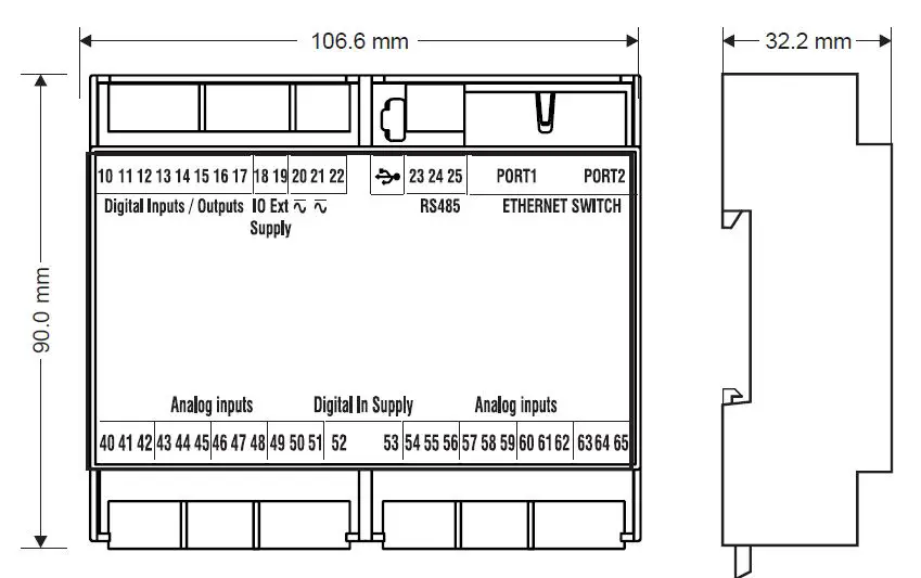
- Weight: 170 g
- Enclosure: UL94-V0 self extinguishing..
- PC/ABS material black.
SIGNALS VIA LED ON FRONT PANEL
| LED | STATUS | LED meaning |
| PWR | On | Device powered |
| Off | Device not powered | |
| IO1/IO8 | On | Digital input/output active |
| Off | Digital input/output not active | |
| OUT SUP | On | Digital inputs/outputs powered |
| Off | Non-digital inputs/outputs powered | |
| STS (Status) | On | IP address set |
| Flashing | Waiting for the IP address from the DHCP | |
| COM R-8AI-8DIDO-P version only | On | Verification of RS485 connection |
| Flashing | Data packet transmission over RS485 | |
| FAIL | On | Digital output in FAIL |
| Off | Digital output OK | |
| RX R-8AI-8DIDO version only | On | RS485 port wiring error |
| Flashing | Reception of data packet completed on RS485 | |
| TXR-8AI-8DIDO version only | Flashing | Reception of data packet completed on RS485 |
| ETH TRF Yellow | Flashing | Packet transit on Ethernet port |
| ETH LNK Green | Flashing | Ethernet port connected |
TECHNICAL SPECIFICATIONS
| CERTIFICATIONS |  https://www.seneca.it/products/r 8ai 8dido/doc/CE declaration |
|
INSULATION |  |
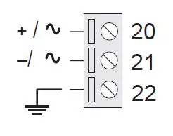
| POWER SUPPLY | Voltage: 10÷40 Vdc; 19÷28 Vac; 50÷65 Hz; Absorption: 3 W |
| ENVIRONMENTAL CONDITIONS | Operating temperature: from -25°C to +65 °C Humidity: 10%– 90% non condensing. Storage temperature: from -30°C to +85 °C Protection rating: IP20 |
| ASSEMBLY | 35mm DIN rail IEC EN60715 |
| CONFIGURATION | With integrated WEB Server R-8AI-8DIDO version only |
| CONNECTIONS COMMUNICATION PORTS | 3.5 mm pitch terminal block, 1.5 mm2 max cable section 1 micro USB port for programming R-8AI-8DIDO version only 2 Ethernet (with LAN fault-bypass function 100 base T on RJ45 RS485 port on terminals R-8AI-8DIDO version only |
| AUXILIARY VOLTAGE OUTPUT | Max voltage/current: 12 Vdc / 20 mA |
| DIGITAL INPUTS | Number of channels: 8; Voltage: Threshold ON: > 9 V; Threshold OFF: < 4 V; Vmax: 24 V Impedance 9 kΩ |
| DIGITAL OUTPUTS | Number of channels: 8, MOSFET, PNP Max voltage/current: 0.2 A / 24 V |
|
ANALOGUE INPUT | Number of channels: 8; Type: voltage, current, thermocouple, thermoresistance Measuring range: Voltage: -30 V ÷ -30 V; -120m V ÷ +120 mV Current: -24 mA ÷ +24 mA Thermocouple: J, K, T, E, N, R, S, B, L. Thermoresistance: PT100: -200 °C ÷ +200 °C only for cold junction offset |
ELECTRICAL CONNECTIONS
The upper power supply limits must not be exceeded, as this could cause serious damage to the module. Switch the module off before connecting inputs and outputs. To meet the electromagnetic immunity requirements use shielded signal cables; connect the shield to a preferential instrumentation earth system; separate shielded cables from other cables used for power installations (transformers, inverters, motors, etc.
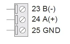
| POWER SUPPLY | RS485 SERIAL PORT
Connection to the RS485 port. Polarity is not standardised and in some devices may be inverted. | CURRENT mA Passive transmitter,with external power supply | |
 |
| ||
| The relative dip switch goes to the ON position | |||
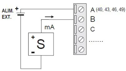
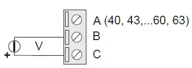
ANALOGUE INPUTS
The device has 8 analogue inputs that can be configured via DIP SDWITCH
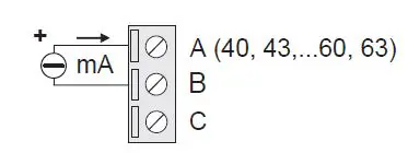
| mA Transmitter active
The relative dipswitch goes to the ON position | VOLTAGE V ±30V
The relative dip-switch goes to the OFF position | THERMOCOUPLE Tc mV
The relative dip-switch goes to the OFF position | ||
| DIGITAL INPUTS PNP | DIGITAL INPUTS PNP | DIGITAL OUTPUTS PNP With external power
externally to function properly. | ||
With external power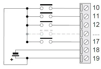 | With internal power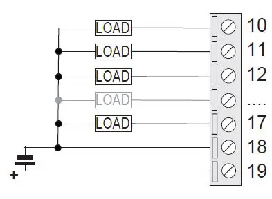 | |||
CAUTION
The input for the RTD thermoresistance is available only for the first channel. For channels 2 to 8 it is not available.
WARNING
The product is not suitable for connection to a dangerous voltage conductor. The maximum allowable voltage is 50 Vac.
THERMORESISTANCE
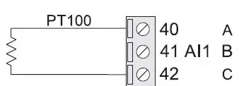
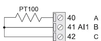
The relative dip-switch goes to the OFF position. Function valid only for analogue input 1.
INSTRUCTIONS FOR ANALOGUE INPUTS
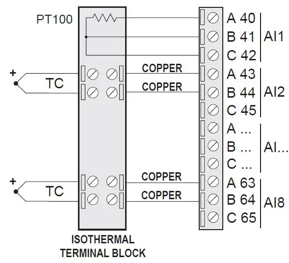
The analogue inputs of this device are designed to measure voltages/currents on floating circuits that is not electrically connected to each other. It is also possible to measure
currents/voltages on non-floating circuits, with a potential difference between negative terminals not exceeding 200 mV. In the case of measurement with thermocouples it is possible to obtain correct measurements even if they are applied to common metal parts. The temperature measurement using thermocouples can be affected by measurement errors due to the determination of the cold junction temperature carried out near the terminal. To eliminate any measurement errors it is necessary to wir the thermocouples on an isothermal terminal board separate from the device.Input No. 1 set as Pt100 will then be used to measure the cold junction temperature of said terminal block.
FEATURE SUMMARY
| ANALOGUE INPUTS | ||||||
| Range | Resolution | Impedance | Precision | Temperature drift | Ext. current | |
| Voltage (V) | -30+30 Vdc | 1 mV | > 200 kohm | 0.1% f.s. | 100 ppm | |
| Voltage (mV) | -120+120 mV | 4 uV | > 10 Mohm | 0.1% f.s. | 100 ppm | |
| Current (mA) | -24..-+24 mA | 0.8 uA | 20 Ohm | 0.2% f.s. | 100 ppm | |
| Thermocouple | -120+120 mV | 4 uV | > 10 Mohm | 0.1% f.s. | 100 ppm | |
| PT100 | -200..200 °C | 0.05 °C | 0.5°C | 50 ppm | 0.5 mA | |
| THERMOCOUPLE TYPE | |||||||
| Range °C | Resolution °C | Impedance Mohm | Precision f.s. | Temperature Drift | Standard | cold junction error °C | |
| J | -210..1200 | 0.1 | > 10 | 0.1% | 100ppm | EN 60584 | 2 |
| K | -200..1372 | 0.1 | > 10 | 0.1% | 100ppm | EN 60584 | 2 |
| T | -200..400 | 0.1 | > 10 | 0.1% | 100ppm | EN 60584 | 2 |
| E | -200..1000 | 0.1 | > 10 | 0.1% | 100ppm | EN 60584 | 2 |
| N | -200..1300 | 0.1 | > 10 | 0.1% | 100ppm | EN 60584 | 2 |
| R | -50..1768 | 0.3 | > 10 | 0.1% | 100ppm | EN 60584 | 2 |
| S | -50..1768 | 0.5 | > 10 | 0.1% | 100ppm | EN 60584 | 2 |
| B | 250..1820 | 0.5 | > 10 | 0.1% | 100ppm | EN 60584 | 2 |
| L | -200..800 | 0.1 | > 10 | 0.1% | 100ppm | GOST:8.585 | 2 |
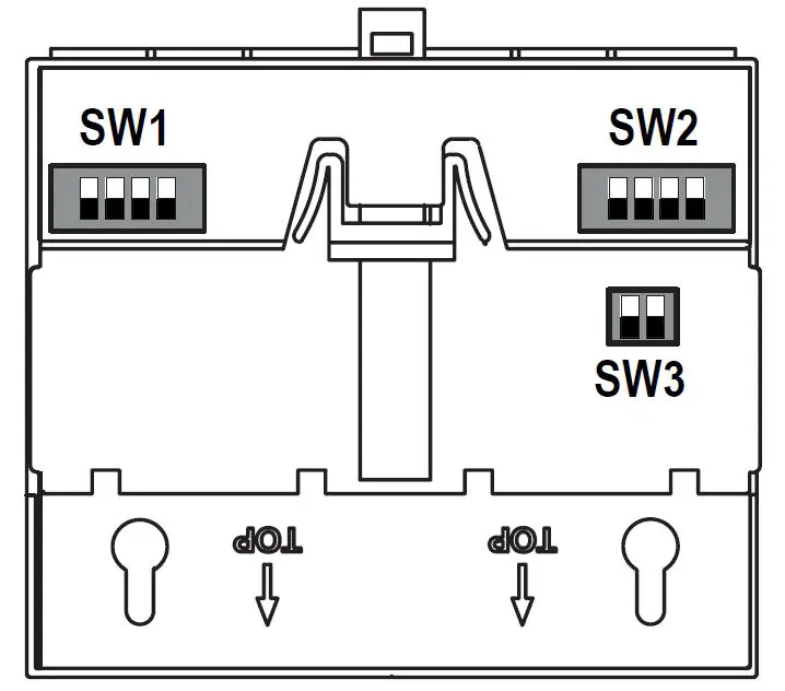
SETTING THE DIP SWITCHES
The DIP-SWITCHES on the back of the device have the following functions:
DIP-SWITCH SW1 AND SW2
ANALOGUE INPUT/OUTPUT CONFIGURATION
| SW1 | SW2 | ||||||
| 1 | 2 | 3 | 4 | 1 | 2 | 3 | 4 |
| AI1 | AI2 | AI3 | AI4 | AI5 | AI6 | AI7 | AI8 |
SW3 DIP-SWITCH
DEFAULT SETTINGS
| SW3 | ||
| DI1 | ON | DEFAULT SETTINGS |
| DIP1 | ON | |
DIP SWITCH positions
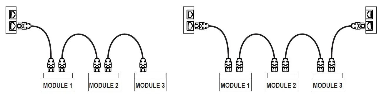
DAISY CHAIN ETHERNET CONNECTION
CAUTION
IT IS NOT ALLOWED TO CREATE LOOPS WITH ETHERNET CABLES. Using the daisy chain connection it is not necessary to use switches to connect the devices.
The following examples show the correct connections.
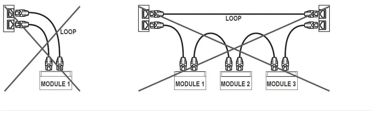
There must be no loops in the Ethernet cabling, otherwise the communication will not work. The modules and switches must be connected eliminating any loops. The following examples show the incorrect connections.
 The LAN fault bypass function allows you to keep the connection between the two Ethernet ports of the device ON, in the event of a power failure. If a device turns off, the chain is not interrupted and the devices downstream of the switched-off one will still be accessible. This function has a limited duration: the connection remains active for a few days, typically .The fault-bypass function requires that the sum of the lengths of the two cables connected to the switched off module is less than 100m
ETHERNET CONNECTION RULES
For the Ethernet cabling between the devices, the use of the unshielded CAT5 or CAT5e cable is required.
FACTORY IP ADDRESS
The default module IP address is static: 192. 168. 90. 101
WEB SERVER
To access the maintenance Web Server with the 192.168.90.101 factory IP address Default user: admin; Default password: admin http://192.168.90.101
CAUTION
DO NOT USE DEVICES WITH THE SAME IP ADDRESS IN THE SAME ETHERNET NETWORK.


