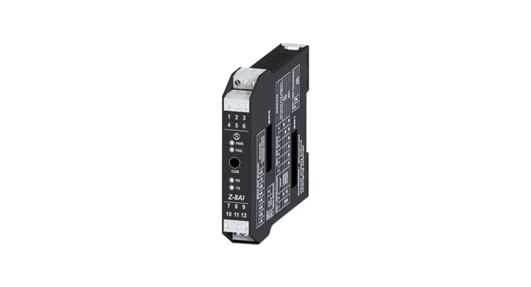
![]() Z-8AI
Z-8AI
INSTALLATION MANUAL
PRELIMINARY WARNINGS
The word WARNING preceded by the symbol![]() indicates conditions or actions that put the user’s safety at risk. The word ATTENTION preceded by the symbol
indicates conditions or actions that put the user’s safety at risk. The word ATTENTION preceded by the symbol![]() indicates conditions or actions that might damage the instrument or the connected equipment. The warranty shall become null and void in the event of improper use or tampering with the module or devices supplied by the manufacturer as necessary for its correct operation, and if the instructions contained in this manual are not followed.
indicates conditions or actions that might damage the instrument or the connected equipment. The warranty shall become null and void in the event of improper use or tampering with the module or devices supplied by the manufacturer as necessary for its correct operation, and if the instructions contained in this manual are not followed.
 | WARNING: The full content of this manual must be read before any operation. The module must only be used by qualified electricians. Specific documentation is available using the QR-CODE shown on page 1. |
 | The module must be repaired and damaged parts replaced by the Manufacturer. The product is sensitive to electrostatic discharges. Take appropriate measures during any operation. |
 | Electrical and electronic waste disposal (applicable in the European Union and other countries with recycling). The symbol on the product or its packaging shows the product must be surrendered to a collection centre authorized to recycle electrical and electronic waste. |
MODULE LAYOUT
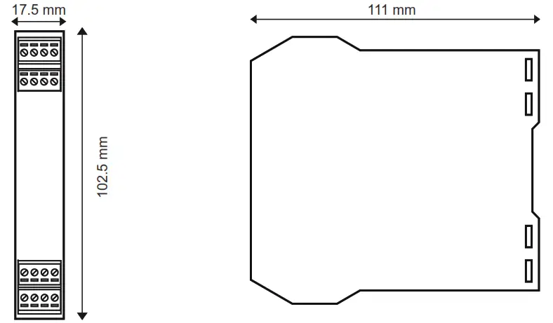
Dimensions LxHxD 17.5 x 102.5 x 111 mm; Weight: 110 g; Enclosure: PA6, black
SIGNALS VIA LED ON FRONT PANEL
| LED | STATUS | LED meaning |
| PWR Green | ON | The device is powered correctly |
| FAIL yellow | Flashing | Anomaly or fault |
| RX Red | Flashing | Receipt of packet completed |
| RX Red | ON | Anomaly / Check connection |
| TX Red | Flashing | Transmission of packet completed |
TECHNICAL SPECIFICATIONS
| CERTIFICATIONS |  https://www.seneca.it/products/z-8ai/doc/CE_declaration https://www.seneca.it/products/z-8ai/doc/CE_declarationNote UL: use in environments with pollution degree 2 or lower. The power supply unit must be class 2. |
| INSULATION | 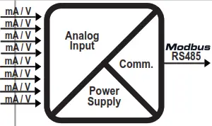 |
| ENVIRONMENTAL CONDITIONS | Temperature: -20 ÷ + 65°C (-10 ÷ +55 °C UL) Humidity: 30% ÷ 90% non condensing. Altitude: up to 2000m above sea level Storage temperature: -20 ÷ + 85°C Protection degree: IP20. |
| ASSEMBLY | 35mm DIN rail IEC EN60715 in vertical position. |
| CONNECTIONS | 3-way removable screw terminals, pitch 5mm Rear connector IDC10 for DIN bar 46277 front micro USB |
| POWER SUPPLY | Voltage: 10 ÷ 40Vdc; 19 ÷ 28Vac; 50 ÷ 60Hz; Absorption: Max. 3.5W |
| INPUTS | |
| Voltage input: | Bipolar with F.S. programmable at +2Vdc and +10Vdc Input impedance >100kOhm |
| Current input: | Bipolar with F.S. Programmable at +20mA with 50Ohm internal shunt selectable via DIP-switch. Available power supply: 90 + 90mA at 13Vdc. |
| Number of channels: | 8 |
| Input resolution: | 15 bit + sign. |
| Input protection: | ± 30Vdc or 25mA |
| Precision voltage and current: | Starting: 0.1 of full scale Linearity : 0.03% of scale. Zero: 0.05% of scale. TC: 100 ppm, EMI: <1 % |
| Sampling time | 120 ms/channel or 60 ms/channel |
| Measurement update time (sampling rate: 10ms) | 1 channel enabled (update time for 1 channel) 4 channels enabled (update time for 4 channels) 8 channels enabled (update time for 8 channels) |
CONFIGURATION OF FACTORY SETTINGS
| All DIP-switches in | OFF position |
| Communication parameters of ModBUS protocol: | 38400 8, N, 1 Address 1 |
| Communication parameters of micro USB front port | 2400 8, N, 1 Address 1 |
| Channel input from 1 to 8: | VOLTAGE ± 10Vdc |
| Numerical representation of the input measurement: | ± 10000mV |
| Sampling time: | 120ms |
SETTING THE DIP-SWITCHES
The position of the DIP-switches defines the Modbus communication parameters of the module: Address and Baud Rate The following table shows the Baud Rate and Address values according to the DIP-switch setting:
| DIP-Switch status | |||||
| SW1 POSITION | BAUD RATE | SW1 POSITION | ADDRESS | POSITION | TERMINATOR |
| 1 2 3 4 5 6 7 8 | 3 4 5 6 7 8 | 10 | |||
| 9600 | #1 | Disabled | |||
| 19200 | #2 | Enabled | |||
| 38400 | ………………………… | #… | |||
| 57600 |  | #63 | |||
 | From EEPROM |  | From EEPROM | ||
Note: When DIP switches 1 to 8 are OFF, the communication settings are taken from programming (EEPROM).
Note 2: The RS485 line must be terminated only at the ends of the communication line.
| SW2 INGRESSI ANALOGICI | ||||||||
| 1 | 2 | 3 | 4 | 5 | 6 | 7 | 8 | CHANNEL |
| CURRENT INPUT | ||||||||
| VOLTAGE INPUT | ||||||||
| LEGEND | |
| ON | |
| OFF | |
The settings of the dip-switches must be compatible with the settings on the registers. The description of the registers is available in the USER MANUAL.
ELECTRICAL CONNECTIONS
Power supply and Modbus interface are available using the Seneca DIN rail bus, via the IDC10 rear connector, or the Z-PC-DINAL-17.5 accessory.
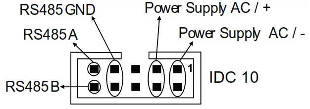
Back connector (IDC 10)
The illustration shows the meanings of the various IDC10 connector pins if signals are to be sent via them directly.
INPUTS
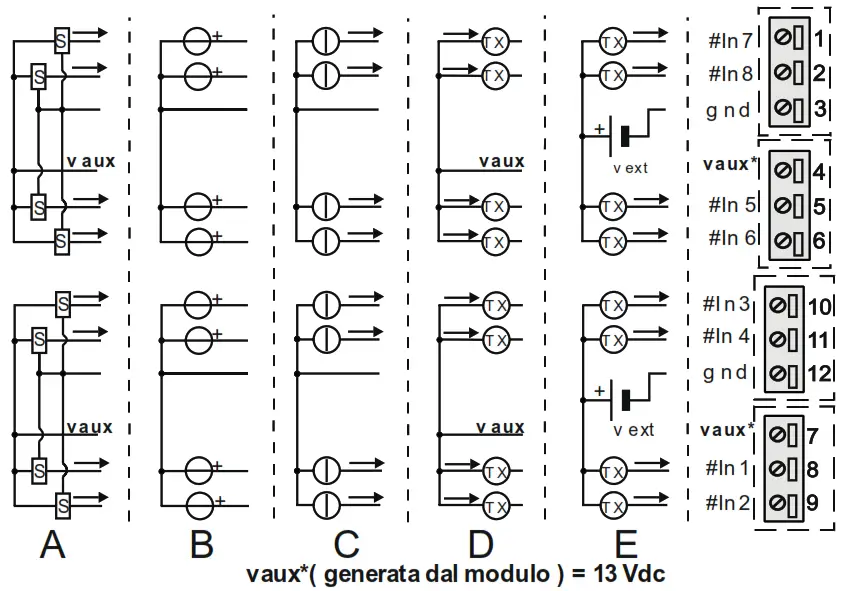
A) Voltage input with sensor supply from the MODULE (13 Vdc)
B) Voltage input with sensor supply NOT coming from the MODULE
C) Current input with sensor supply NOT coming from the MODULE
D) Current input with sensor supply from the MODULE (13 Vdc)
E) Current input with sensor EXTERNAL power supply![]() ATTENTION
ATTENTION
The upper power supply limits must not be exceeded, as this might cause serious damage to the module. Switch the module off before connecting inputs and outputs.
To meet the electromagnetic immunity requirements:
- use shielded signal cables;
- connect the shield to a preferential instrumentation earth system;
- separate shielded cables from other cables used for power installations (inverters, motors, induction ovens, etc…).
- install a fuse with a MAX capacity of 2.5A near the module.
- make sure that the power supply voltage to the module does not exceed: 40Vdc or 28Vac, otherwise the module will be damaged.
![]()
![]() SENECA s.r.l.; Via Austria, 26 – 35127 – PADOVA – ITALY;
SENECA s.r.l.; Via Austria, 26 – 35127 – PADOVA – ITALY;
Tel. +39.049.8705359 – Fax +39.049.8706287
CONTACT INFORMATION
Technical support
[email protected]
Product information
[email protected]
This document is the property of SENECA srl. Copies and reproduction are prohibited unless authorised.
The content of this document corresponds to the described products and technologies.
Stated data may be modified or supplemented for technical and/or sales purposes. www.seneca.it/products/z-8ai


