SENECA UL94-V0 Gateway Radio Instruction Manual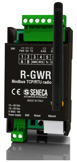
PRELIMINARY WARNINGS
The word WARNING preceded by the symbol ![]() indicates conditions or actions that put the user’s safety at risk.
indicates conditions or actions that put the user’s safety at risk.
The word ATTENTION preceded by the symbol ![]() indicates conditions or actions that might damage the
indicates conditions or actions that might damage the
instrument or the connected equipment. The warranty shall become null and void in the event of improper use or tampering with the module or devices supplied by the manufacturer as necessary for its correct operation, and if the instructions contained in this manual are not followed.
![]() WARNING: The full content of this manual must be read before any operation. The module must only be used by qualified electricians. Specific documentation is available via QR-CODE shown on page 1.
WARNING: The full content of this manual must be read before any operation. The module must only be used by qualified electricians. Specific documentation is available via QR-CODE shown on page 1.
 The module must be repaired and damaged parts replaced by the Manufacturer. The product is sensitive to electrostatic discharges. Take appropriate measures during any operation.
 Electrical and electronic waste disposal (applicable in the European Union and other countries with recycling). The symbol on the product or its packaging shows the product must be surrendered to a collection centre authorized to recycle electrical and electronic waste.
DOCUMENTATION R-COMM
ENECA s.r.l.; Via Austria, 26 – 35127 – PADOVA – ITALY; Tel. +39.049.8705359 – Fax +39.049.8706287
CONTACT INFORMATION
Technical support: [email protected]
Product information: [email protected]
This document is the property of SENECA srl. Copies and reproduction are prohibited unless authorised.
The content of this document corresponds to the described products and technologies.
Stated data may be modified or supplemented for technical and/or sales purposes.
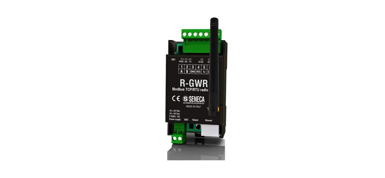
MODULE LAYOUT
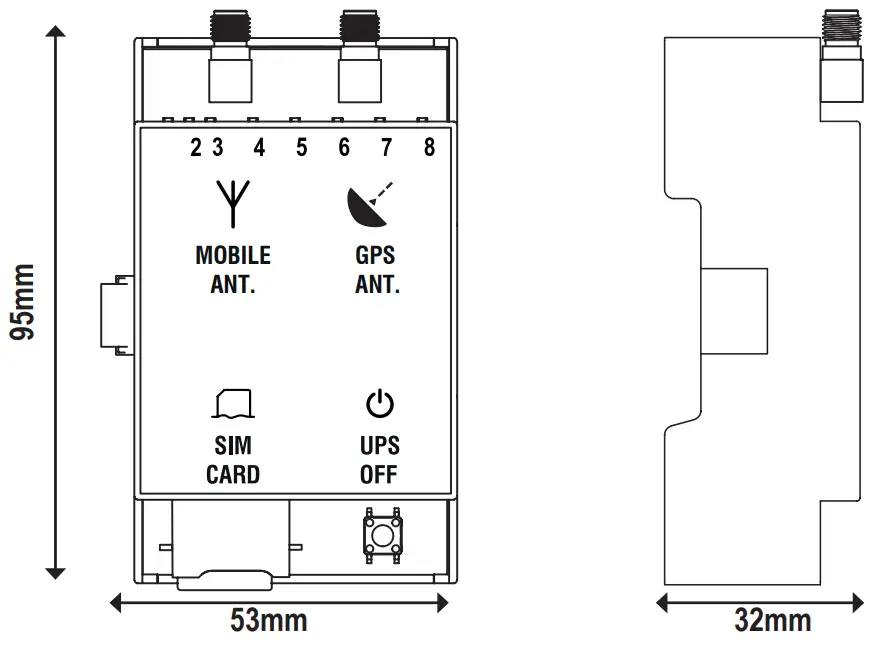
Weight: 80 g;
Enclosure: UL94-V0 self-extinguishing PC/ABS material, black. 95mm
SIGNALS VIA LED ON FRONT PANEL
| LED | STATUS | LED meaning |
| On | Signal level reporting |
| Flashing | Modem not correctly adjusted | |
| NET | On | Modem adjusted on 4G network |
| Flashing | Modem adjusted on 2G or 3G network | |
| Off | Modem off or not adjusted | |
| DATA | On | Data connection enabled and correctly adjusted |
| Flashing | Data connection enabled but in error | |
| Off | Data connection disabled | |
| GPS | On | GPS signal present |
| Off | GPS signal absent | |
| BAT | On | Battery connected and working properly |
| Flashing | Low or faulty battery | |
| Off | Battery not in use (UPS not active) | |
| PWR | On | Module powered / successful connection |
| Off | Module not powered / instrument not connected |

TECHNICAL SPECIFICATIONS
| CERTIFICATIONS |
|
| POWER SUPPLY | Through connection with the main module |
| BACKUP BATTERY (R-COMM-B-4GWW ONLY) | Nickel battery AA dimension 1250mAh; 3.6V |
| ENVIRONMENTAL CONDI- TIONS | Temperature: -25°C ÷ +65°C Humidity: 30% ÷ 90% non-condensing Storage temperature: -30 °C ÷ + 85 °C Protection rating: IP20 |
| ASSEMBLY | DIN rail 35 mm IEC EN60715 or wall with screws |
| CONNECTIONS | 1 SIM-CARD slot 1 SMA connector for GPS antenna 1 SMA connector for 4G/LTE antenna |
| 4G MODEM FREQUENCIES | Global coverage Model 4G/LTE LTE-FDD: B1/B2/B3/B4/B5/B7/B8/B12/B13/B18/ B19/B20/B25/B26/B28 LTE-TDD: B38/B39/B40/ B41 WCDMA: B1/B2/B4/B5/B6/B8/B19/GSM: B2/B3/B5/B |
| OUTPUT POWER | GSM900: 32.75dBm, DCS1800: 29.07dBm, WCDMC: 23.13dBm, 23.27 dBm, LTE: 23.1dBm, 23.2dBm, 21.7dBm, 23.19dBm, 23.14dBm, 23.7dBm, 23.39dBm. |
| GNSS | GPS / GLONASS / BeiDou (compass) / Galileo / QZSS |
| SIM CARD SLOT | Push-push type for mini SIM card 15 X 25 mm |


N.B.: To purchase the “GPS antenna” accessory, access the website www.seneca.it and go to the product page.
Button used to switch the UPS off:
The button is located on the underside of the instrument.
To shut down the UPS of the device, simply press the OFF button, in doing so the power supplied by the battery pack for the UPS will be disabled.
To switch off the R-PASS main module, it is necessary to disconnect the power cables from the terminals.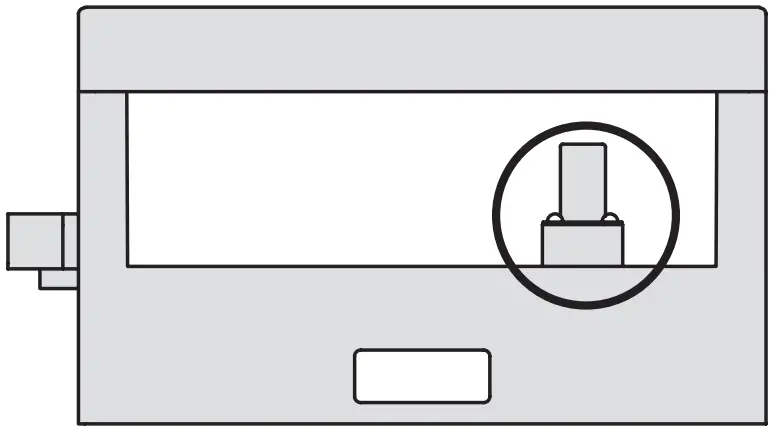
CONNECTION TO THE MAIN MODULE
Installation:
To connect the R-COMM accessory module to the R-PASS main module, position the instrument on the DIN rail as shown in the procedure below, then slide the module until it is fully engaged with the side connector.
After the correct connection, the PWR led turns on to show the power supply.
![]() CAUTION
CAUTION
The connection of the R-COMM accessory module must be made with the R-PASS main module turned off.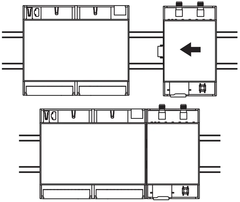
N.B.: For an ideal operation of the module, the use of a DIN rail clamp is recommended.
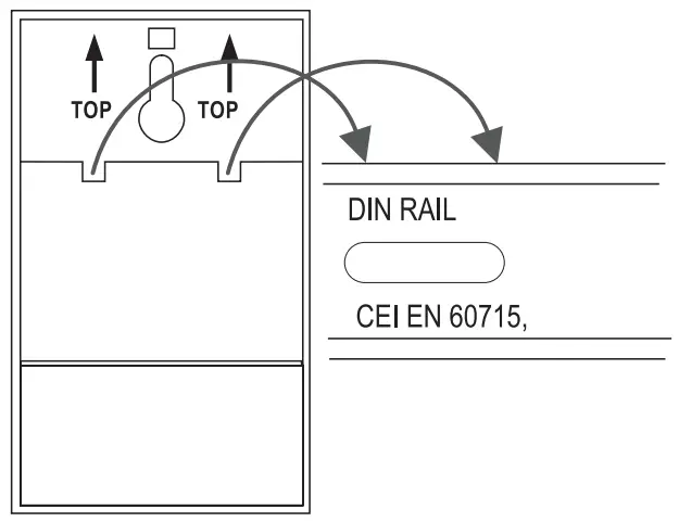
INSTALLATION ON DIN-IEC EN 60715 RAIL
Installation:
Position the device on the OMEGA rail resting the upper teeth from top to bottom.
Push the lower part towards the rail until the locking system engages.
Removal:
After switching off the module, with the help of a slotted screwdriver, unlock the locking system located on the underside of the instrument.