SENECA Z-8TC-SI Analog I-O Module Installation Guide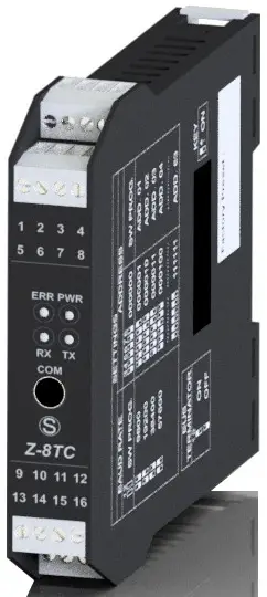
PRELIMINARY WARNINGS
The word WARNING preceded by the symbol ![]() indicates conditions or actions that put the user’s safety at risk.
indicates conditions or actions that put the user’s safety at risk.
The word ATTENTION preceded by the symbol indicates conditions or actions that might damage the instrument or the connected equipment. The warranty shall become null and void in the event of improper use or tampering with the module or devices supplied by the manufacturer as necessary for its correct operation, and if the instructions contained in this manual are not followed.
![]() WARNING: The full content of this manual must be read before any operation. The module must only be used by qualified electricians. Specific documentation is available via QR-CODE.
WARNING: The full content of this manual must be read before any operation. The module must only be used by qualified electricians. Specific documentation is available via QR-CODE.
![]() The module must be repaired and damaged parts replaced by the Manufacturer. The product is sensitive to electrostatic discharges. Take appropriate measures during any operation.
The module must be repaired and damaged parts replaced by the Manufacturer. The product is sensitive to electrostatic discharges. Take appropriate measures during any operation.
Electrical and electronic waste disposal (applicable in the European Union and other countries with recycling). The symbol on the product or its packaging shows the product must be surrendered to a collection centre authorized to recycle electrical and electronic waste.
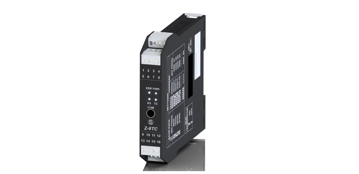
MODULE LAYOUT
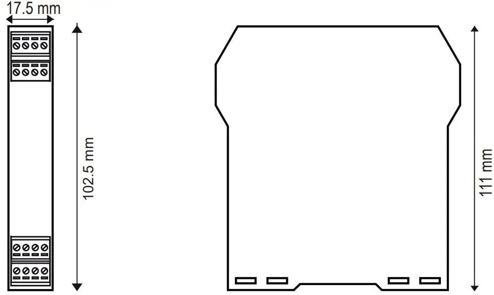
- Dimensions: 17.5 x 102.5 x 111 mm
- Weight: 100 g
- Container: PA6, black
SIGNALS VIA LED ON FRONT PANEL
| LED | STATUS | LED meaning |
| PWR | ON | The device is powered correctly |
| FAIL | ON | Instrument in error state |
| RX | Flashing | Data receipt on port #1 RS485 |
| TX | Flashing | Data transmission on port #1 RS485 |
TECHNICAL SPECIFICATIONS
| CERTIFICATIONS |  https://www.seneca.it/products/z8tc-si/doc/CE_declaration  https://www.seneca.it/products/z8tc-si-lab/doc/CE_declaration  |
| POWER SUPPLY | Voltage: 10 ÷ 40Vdc; 19 ÷ 28Vac; 50-60 Hz; absorption: 0.6W max |
| ENVIRONMENTAL CONDITIONS | Operating temperature: -25°C ÷ +70°C. Humidity: 30% ÷ 90% non condensing. Storage temperature: -30°C ÷ +85°C Altitude: Up to 2000 m above sea level Protection rating: IP20 |
| ASSEMBLY | 35mm DIN rail IEC EN60715 |
| CONNECTIONS | 4-way removable terminal block, 3.5mm pitch, 1.5 mm2 cable section max |
| COMMUNICATION PORTS | IDC10 rear connector for IEC EN 60715 DIN bar, ModBUS-RTU, 1200÷115200 Baud Micro USB on the front, ModBUS protocol, 2400 Baud |
| INSULATION | 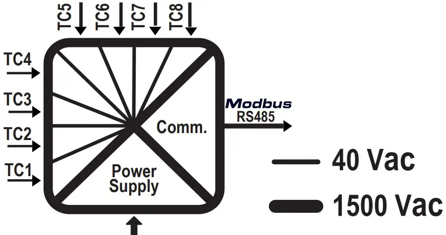 |
| COMMUNICATION PORTS | RS485 on IDC10 connector |
| PROTOCOL | ModBUS- RTU |
| TC INPUTS | No. of channels: 8; Type of thermocouples: J, K, E, N, S, R, B, T, L (individually activated and configurable in pairs) |
N.B.: A delayed fuse with a maximum rating of 2.5 A must be installed in series with the power supply connection, near the module.
SUPPORTED INPUT SPECIFICATIONS
| SENSOR | ACCURACY (AT 23°C) | SOLUTION | MEASURING RANGE | STANDARD |
| J | ± (0.03% + 0.2°C) (**) | 0.5µV (~0.01°C @ 0°C) | -210 ÷ +1200°C | EN 60584-1:1997 |
| K | ± (0.03% + 0.2°C) (**) | 0.5µV (~0.02°C @ 0°C) | -200 ÷ +1372°C | EN 60584-1:1997 |
| R | ± (0.03% + 0.3°C) (**) | 0.5µV (~0.1°C @ 0°C) | -50 ÷ +1768°C | EN 60584-1:1997 |
| S | ± (0.03% + 0.3°C) (**) | 0.5µV (~0.1°C @ 0°C) | -50 ÷ +1768°C | EN 60584-1:1997 |
| T | ± (0.03% + 0.1°C) (**) | 0.5µV (~0.01°C @ 0°C) | -200 ÷ +400°C | EN 60584-1:1997 |
| B | ± (0.03% + 0.3°C) (**) | 0.5µV (~0.2°C @ 0°C) | +250 ÷ +1820°C (*) | EN 60584-1:1997 |
| E | ± (0.03% + 0.2°C) (**) | 0.5µV (~0.01°C @ 0°C) | -200 ÷ +1000°C | EN 60584-1:1997 |
| N | ± (0.03% + 0.2°C) (**) | 0.5µV (~0.02°C @ 0°C) | -200 ÷ +1300°C | EN 60584-1:1997 |
| L | ± (0.03% + 0.15°C) (**) | 0.5µV (~0.01°C @ 0°C) | -200 ÷ +800°C | Gost 8.585-2001 |
| mV | 0.03% + 15µV | 0.5µV | ± 150 mV |
(*) Up to 250°C a zero temperature value is assumed.
(**) Acquisition speed 100ms, no cold junction compensation.
![]() CAUTION
CAUTION
Even at constant room temperature, the declared accuracies are achieved after at least 30 minutes from switching on the device.
| SPAN mV | ±150mV. |
| IMPEDANCE | > 4MΩ. |
| ADC | 24 bit. |
| TEMPERATURE DRIFT | < 100ppm/K. |
| COLD JUNCTION ERROR | <1°C. |
| TEST CURRENT | <100nA. |
| CMRR | 70dB @ 100ms |
| DMRR | 60 dB. |
SETTING THE DIP-SWITCHES
The position of the DIP-switches defines the Modbus communication parameters of the module: Address and Baud Rate The following table shows the values of the Baud Rate and the Address according to the setting of the DIP-switches:
| DIP-Switch status | ||||
| SW1 POSITION | BAUDRATE | SW1 POSITION | POSITION | FUNCTION |
| 1 2 3 4 5 6 7 8 | 3 4 5 6 7 8 | 9 | BOOTLOADER | |
 ———– ———– | 9600 |  | Enabled | |
 ———– ———– | 19200 |  | Disabled | |
 ——- ——- | 38400 | 10 | TERMINATOR | |
| 57600 |  | Enabled | ||
 | From |  | Disabled | |
| EEPROM | ||||
Note: When DIP – switches 1 to 8 are OFF, the communication settings are taken from programming (EEPROM).
Note 2: The RS485 line must be terminated only at the ends of the communication line.
| FACTORY SETTINGS | |||||||
| 1 | 2 | 3 | 4 | 5 | 6 | 7 | 8 |
| KEY | |
| ON | |
| OFF | |
The position of the dip-switches defines the communication parameters of the module. The default configuration is as follows: Address 1, 38400, no parity, 1 stop bit.
INSTALLATION REGULATIONS
The module has been designed for vertical installation on a DIN 46277 rail. For optimal operation and long life, adequate ventilation must be provided. Avoid positioning ducting or other objects that obstruct the ventilation slots. Avoid mounting modules over heat-generating equipment. Installation in the bottom part of the electrical panel is recommended.
![]() CAUTION
CAUTION
These are open type devices intended for installation in a final casing/panel that offers mechanical protection and protection against the spread of fire.
ELECTRICAL CONNECTIONS
![]() CAUTION
CAUTION
To meet the electromagnetic immunity requirements:
- use shielded signal cables;
- connect the shield to a preferential instrumentation earth system;
- separate shielded cables from other cables used for power installations (transformers, inverters, motors, etc.).
Power supply and Modbus interface are available using the Seneca DIN rail bus, via the IDC10 rear connector, or the Z-PC-DINAL-17.5 accessory.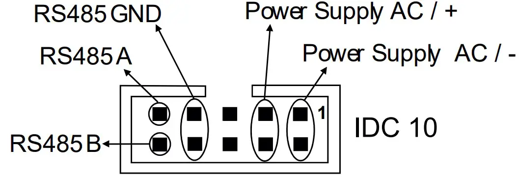
Back connector (IDC 10)
The illustration shows the meanings of the various IDC10 connector pins if signals are to be sent via them directly
Z-8TC-SI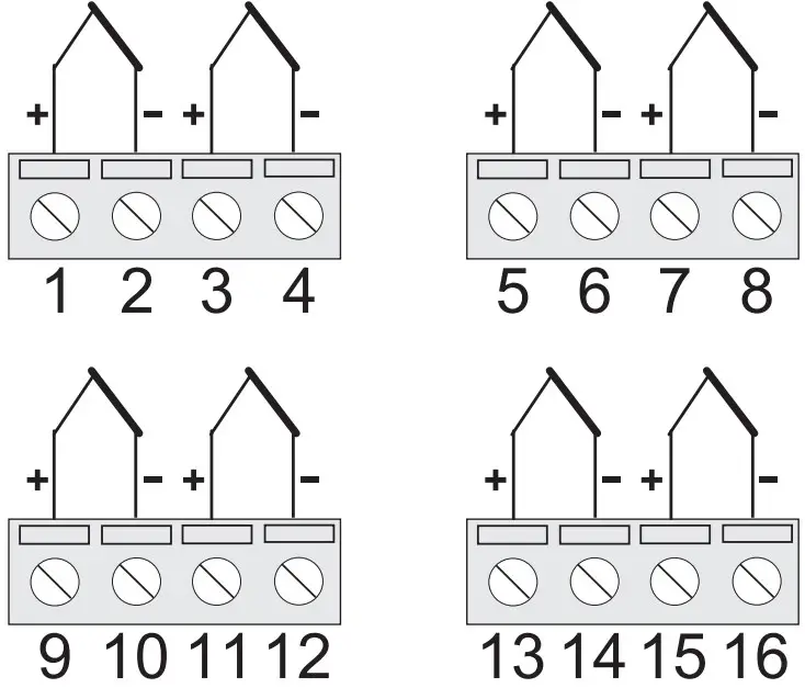
Z-8TC-SI-LAB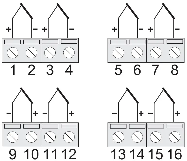
MODBUS CONNECTION RULES
- Install the modules in the DIN rail (120 max)
- Connect the remote modules using cables of an appropriate length. The following table shows cable length data:
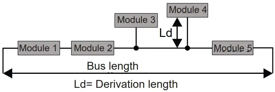
- Bus length: maximum length of the Modbus network according to the Baud Rate. This is the length of the cables that connect the two farthest modules (see Diagram 1).
- Derivation length: maximum length of a derivation 2 m (see Diagram 1).
Bus length Derivation length 1200 m 2 m 
For maximum performance, it is recommended to use special shielded cables manufactured specifically for RS485 communication.
CONTACT INFORMATION
Technical support: [email protected]
Product information: [email protected]
This document is the property of SENECA srl. Copies and reproduction are prohibited unless authorised. The content of this document corresponds to the described products and technologies. Stated data may be modified or supplemented for technical and/or sales purposes.


