SENECA Z-KEY-MBUS Protocol Converter Installation Guide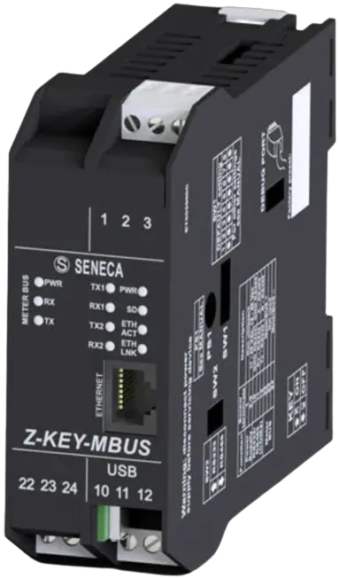
PRELIMINARY WARNINGS
The word WARNING preceded by the symbol ![]() indicates conditions or actions that put the user’s safety at risk.
indicates conditions or actions that put the user’s safety at risk.
The word ATTENTION preceded by the symbol ![]() indicates conditions or actions that might damage the instrument or the connected equipment. The warranty shall become null and void in the event of improper use or tampering with the module or devices supplied by the manufacturer as necessary for its correct operation, and if the instructions contained in this manual are not followed.
indicates conditions or actions that might damage the instrument or the connected equipment. The warranty shall become null and void in the event of improper use or tampering with the module or devices supplied by the manufacturer as necessary for its correct operation, and if the instructions contained in this manual are not followed.
| WARNING: The full content of this manual must be read before any operation. The module must only be used by qualified electricians. Specific documentation is available via QR-CODE shown on page 1. |
| The module must be repaired and damaged parts replaced by the Manufacturer. The product is sensitive to electrostatic discharges. Take appropriate measures during any operation. |
| Electrical and electronic waste disposal (applicable in the European Union and other countries with recycling). The symbol on the product or its packaging shows the product must be surrendered to a collection centre authorized to recycle electrical and electronic waste. |


DOCUMENTATION
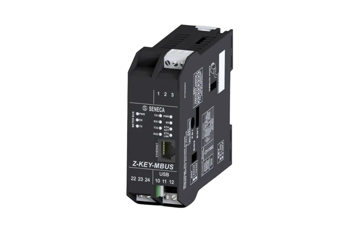
MODULE LAYOUT
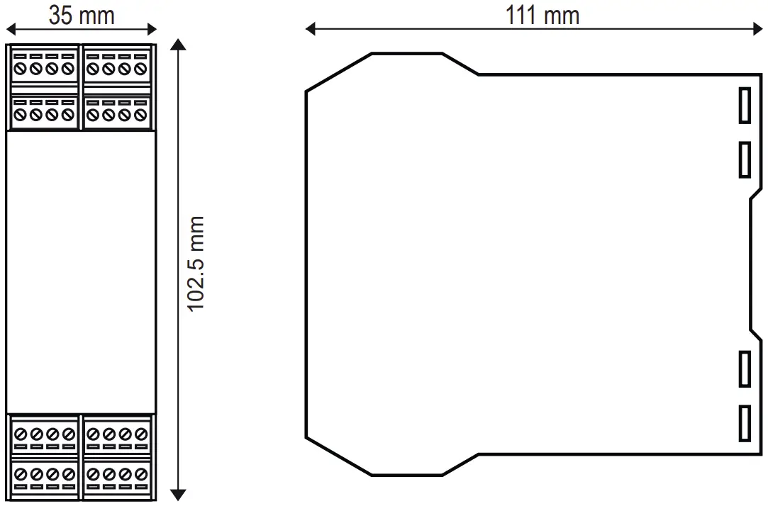
Dimensions: 35 x 102.5 x 111 mm,
Weight: 190 g;
Enclosure: PA6, black
SIGNALS VIA LED ON FRONT PANEL
| LED | STATUS | LED meaning |
| PWR | ON | The device is powered correctly |
| COM Only Z- KEY MBUS-P | Flashing | Profinet communication active |
| Off | No Profinet communication | |
| TX1 | Flashing | Data transmission on port #1 RS485 |
| RX1 | Flashing | Data receipt on port #1 RS485 |
| TX2 | Flashing | Data transmission on port #2 RS485/RS232 |
| RX2 | Flashing | Data reception on port #2 RS485/RS232 |
| ETH ACT Green | Flashing | Packet transmission on Ethernet port |
| ETH LNK Yellow | ON | Ethernet connection present |
TECHNICAL SPECIFICATIONS
| CERTIFICATIONS | https://www.seneca.it/products/z-key-mbus/doc/CE_declaration |
| INSULATION | 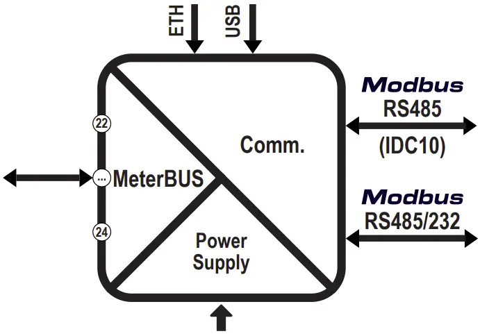 |
| ENVIRONMENTAL CONDITIONS | Temperature: -25 °C – +65 °C; Humidity: 30% – 90% non condensing. Altitude: Up to 2000 m above sea level Storage temperature: -30 °C – +85 °C; Degree of protection: IP20 |
| ASSEMBLY | IEC EN60715, 35mm DIN rail in vertical position. |
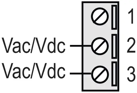
| POWER SUPPLY | Voltage: 11-40 Vdc; 19-28 Vac; 50-60 Hz; Absorption: Typical: 3,5W, max. 6.5 W |


| CONNECTIONS | 3-way removable screw terminals, pitch 5 mm Rear connector IDC10 for DIN bar 46277 RJ45 front connector |
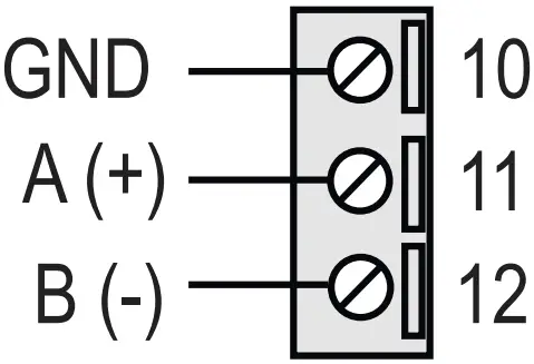
| COMMUNICATION PORTS | RS242 or RS485 switchable on terminal 10 – 11 – 12 (serial port 2) Maximum Baud rate 115 k, maximum cable length RS232 < 3m RS485 IDC10 rear connector: Maximum Baud rate 115 k. (serial port 1) RJ45 front Ethernet connector: 100 Mbit/s, maximum distance 100 m Side micro USB port |
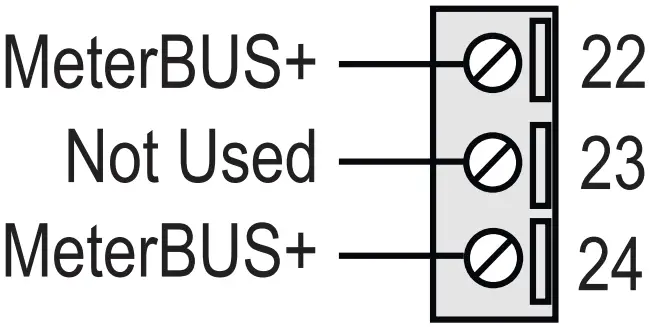
| M-Bus PORT (on terminals 22-24) | Number of slaves: maximum 25 devices. Speed: 300 – 38400 bps Voltage: 28Vdc Maximum length: 3000m |
| CONFIGURATION | Configuration and FW update via webserver; Via DIP – SWITCH Via EASY SETUP 2 configuration software |
SETTING THE DIP-SWITCHES
![]() WARNING
WARNING
The DIP-switch settings are read only at boot time. At each change, perform a restart.
SW1 DIP-SWITCH:
Through DIP-SWITCH-SW1 it is possible to set the IP configuration of the device:
| DESCRIPTION | DIP 1 | DIP 2 | DIP 3 | DIP 4 |
| To obtain the configuration from the Flash memory, both SW1 DIP switch selectors must be set to OFF |
|
| RESERVED | RESERVED |
| To reset the device to factory settings both SW1 DIP switches must be set to ON |
|
| RESERVED | RESERVED |
| To force the device’s IP address to the standard value of the SENECA Ethernet products: 192.168.90.101 |
|
| RESERVED | RESERVED |
| Reserved |
|
| RESERVED | RESERVED |


KEY
| 1 | ON |
|
| 0 | OFF |
|


![]() CAUTION
CAUTION
Where present, DIP3 and DIP4 must be set to OFF.
If set differently, the instrument will not work correctly.
RS232/RS485 SETTING: RS232 or RS485 configuration on terminals 10-11-12 (serial port 2)
SW2 | |||
| 1 | ON |
| RS232 ACTIVATION |
| 0 | OFF |
| RS485 ACTIVATION |
FACTORY IP ADDRESS
The default module IP address is static: 192.168.90.101
WEB SERVER
To access the maintenance Web Server with 192.168.90.101 factory IP address enter:
http://192.168.90.101
Default user: admin, Default password: admin
N.B.: For the Z-KEY-MBUS-P version it is first necessary to activate webserver mode.
![]() CAUTION
CAUTION
DO NOT USE DEVICES WITH THE SAME IP ADDRESS IN THE SAME ETHERNET NETWORK.
WEB SERVER AND PROFINET MODE (Z-KEY-MBUS-P)
The device is normally in Profinet mode; in Profinet mode the device can be configured only through the Easy Setup 2 software.
In order to access the internal webserver it is necessary to put the device in Webserver mode using the Easy Setup 2 or Seneca Device Discovery software. It is also possible to change the operating mode by pressing the side button following the procedure:
To force webserver mode:
- Keep the “PS1” button pressed until all the LEDs go off
- Release the button
- The device restarts and the PWR and COM LEDs flash slowly to indicate webserver mode
To force Profinet mode:
- Keep the “PS1” button pressed until all the LEDs go off
- Release the button
- The device restarts and the PWR and COM LEDs stop flashing slowly to indicate Profinet mode
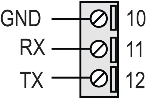
IDC10 CONNECTOR
The illustration shows the meanings of the various IDC10 connector pins if signals are to be sent via them directly.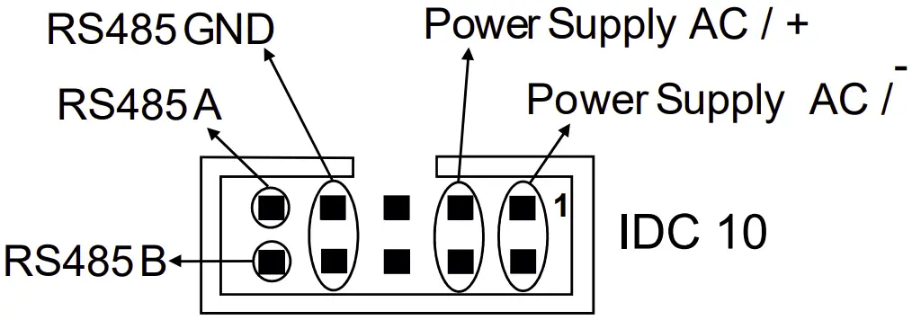
INSTALLATION REGULATIONS
The module has been designed for vertical installation on a DIN 46277 rail. For optimal operation and long life, adequate ventilation must be provided. Avoid positioning ducting or other objects that obstruct the ventilation slots. Avoid mounting modules over heat-generating equipment. Installation in the bottom part of the electrical panel is recommended.
![]() CAUTION
CAUTION
These are open type devices intended for installation in a final casing/panel that offers mechanical protection and protection against the spread of fire.
ELECTRICAL CONNECTIONS
![]() CAUTION
CAUTION
To meet the electromagnetic immunity requirements:
- use shielded signal cables;
- connect the shield to a preferential instrumentation earth system;
- separate shielded cables from other cables used for power installations (transformers, inverters, motors, etc…).
| POWER SUPPLY | RS485 SERIAL PORT SW2 = OFF | RS232 SERIAL PORT SW2 = ON | Meter-Bus PORT |
|
|
|
|
![]() CAUTION
CAUTION
Use only copper or copper-coated aluminum or AL-CU or CU-AL conductors
CONNECTION STANDARDS
| Type of installation | Maximum speed | Connection maximum distance | Connection total length | Type of cable |
| Small in house | 38400 | < 350 m | < 1000 m | 0.5 mm2, R < 30 Ω |
| Large in house | 9600 | < 350 m | < 3000 m | 0.5 mm2, R < 30 Ω |
| Small wide area | 2400 | < 1000 m | < 3000 m | 1.5 mm2, R < 90 Ω |
Meter BUS is a non-polarized bus. For the connection it is possible to use a two-wire shielded telephone cable or an unshielded duplex cable following the indications in the table.
If a shielded cable is used, this must be connected to earth only from the side of the Z-KEY-MBUS instrument.
CONTACT INFORMATION
SENECA s.r.l.; Via Austria, 26 – 35127 – PADOVA – ITALY;
Tel. +39.049.8705359 –
Fax +39.049.8706287
Technical support
[email protected]
Product information
[email protected]