SENECA S117P1 Serial or USB Converters Instruction Manual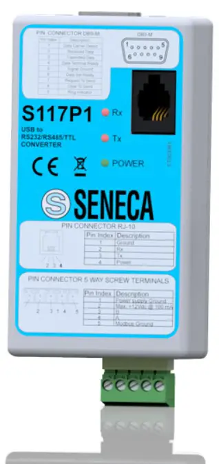
PRELIMINARY WARNINGS
![]() The word WARNING preceded by the symbol indicates conditions or actions that put the user’s safety at risk.
The word WARNING preceded by the symbol indicates conditions or actions that put the user’s safety at risk.![]() The word ATTENTION preceded by the symbol indicates conditions or actions that might damage the instrument or the connected equipment. The warranty shall become null and void in the event of improper use or tampering with the module or devices supplied by the manufacturer as necessary for its correct operation, and if the instructions contained in this manual are not followed.
The word ATTENTION preceded by the symbol indicates conditions or actions that might damage the instrument or the connected equipment. The warranty shall become null and void in the event of improper use or tampering with the module or devices supplied by the manufacturer as necessary for its correct operation, and if the instructions contained in this manual are not followed.
 | WARNING: The full content of this manual must be read before any operation. The module must only be used by qualified electricians. Specific documentation is available via QR-CODE shown on page 1. |
 | The module must be repaired and damaged parts replaced by the Manufacturer. The product is sensitive to electrostatic discharges. Take appropriate measures during any operation. |
 | Electrical and electronic waste disposal (applicable in the European Union and other countries with recycling). The symbol on the product or its packaging shows the product must be surrendered to a collection centre authorized to recycle electrical and electronic waste. |
DOCUMENTATION S117P1
CONTACT INFORMATION
| Technical support | [email protected] | Product information | [email protected] |
This document is the property of SENECA srl. Copies and reproduction are prohibited unless authorised. The content of this document corresponds to the described products and technologies. Stated data may be modified or supplemented for technical and/or sales purposes.
SIGNALS VIA LED ON FRONT PANEL
| LED | STATUS | LED meaning | |
| PWR Green | ON | The device is powered correctly | |
| RX Red | ON flashing | It lights up every time the instrument receives data through the RS485 / RS232 port | |
| TX Red | ON flashing | It lights up every time the instrument transmits data through the RS485 / RS232 port | |
TECHNICAL SPECIFICATIONS
CERTIFICATIONS
![]()
https://www.seneca.it/products/s117p1/doc/CE_declaration

INSULATION
![]() WARNING
WARNING
the maximum working voltage between any terminal and ground must be less than 50 Vac / 75Vdc
ENVIRONMENTAL CONDITIONS | Operating temperature: -20 ÷ + 65°C; Humidity: 10% ÷ 90% non-condensing;Altitude: Up to 2000 m a.s.l.; Storage temperature -40 ÷ +85°; Degree of protection: IP20. |
ASSEMBLY | IEC EN60715, 35mm DIN rail through terminals. |
CONNECTIONS | 5-way removable screw terminals, pitch 5 mm |
POWER SUPPLY | Through PC USB port. |
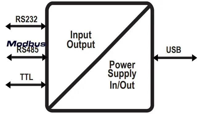
SERIAL COMMUNICATION | RS232 (DB9-M), RS485 (5 poles), TTL (RJ10), USB 1.0, 1.1, 2.0 |
BAUD RATE | 1200bps, 115200bps. |
DIMENSIONS | Width: 90mm; Height: 50mm; Depth: 25mm; Weight: 55 g |
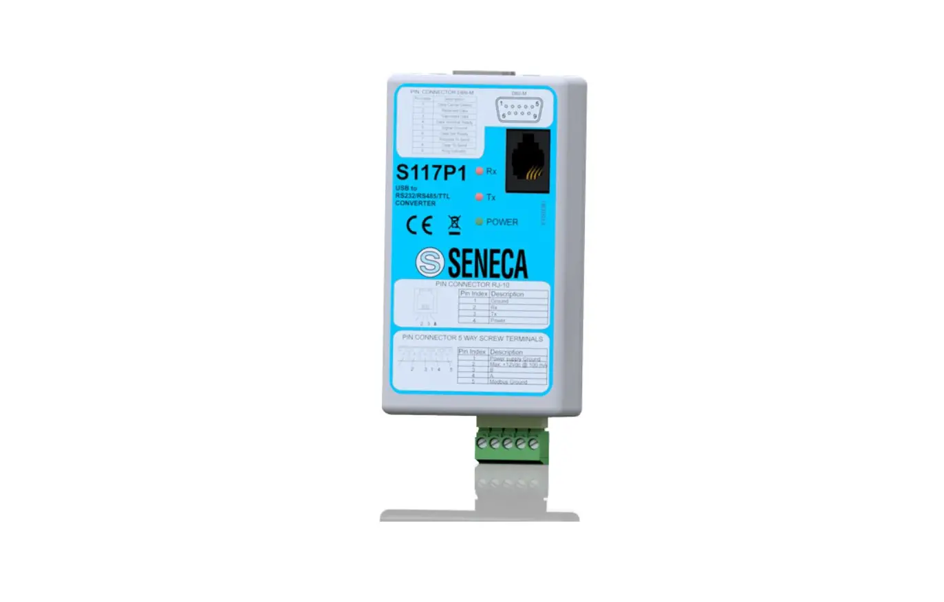
TERMINAL POSITION AND DESCRIPTION
The drawing below shows the functions of the removable screw connector on the side of the S117P1:
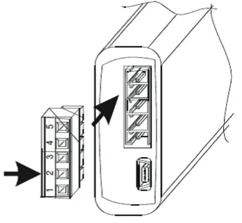
| PIN INDEX | DESCRIPTION |
| 1 | Power Supply Ground |
| 2 | Max: + 12Vdc @ 100 mA |
| 3 | B |
| 4 | A |
| 5 | Modbus Ground |
![]() CAUTION
CAUTION
For long connections or in noisy environments, use a shielded cable for the RS232 and RS485 lines
TROUBLESHOOTING
If problems occur with the use of the converter, check the following points
| PROBLEM | CHECK |
| The “POWER” LED does not come on | Check that the PC’s USB socket provides for the supply of the 5 V needed to power the instrument |
| The “Rx” led remains on continuously | Check that the RS485 or RS232 cables have not been swapped |
| The received data is incorrect | Check the communication speed |


