INSTALLATION MANUAL
Z-LTE-WW
Z-LTE-EU
PRELIMINARY WARNINGS
The word WARNING preceded by the symbol ![]() indicates conditions or actions that put the user’s safety at risk. The word ATTENTION preceded by the symbol
indicates conditions or actions that put the user’s safety at risk. The word ATTENTION preceded by the symbol ![]() indicates conditions or actions that might damage the instrument or the connected equipment. The warranty shall become null and void in the event of improper use or tampering with the module or devices supplied by the manufacturer as necessary for its correct operation, and if the instructions contained in this manual are not followed.
indicates conditions or actions that might damage the instrument or the connected equipment. The warranty shall become null and void in the event of improper use or tampering with the module or devices supplied by the manufacturer as necessary for its correct operation, and if the instructions contained in this manual are not followed.
 | WARNING: The full content of this manual must be read before any operation. The module must only be used by qualified electricians. Specific documentation is available via QR-CODE shown on page 1. |
 | The module must be repaired and damaged parts replaced by the Manufacturer. The product is sensitive to electrostatic discharges. Take appropriate measures during any operation. |
 | Electrical and electronic waste disposal (applicable in the European Union and other countries with recycling). The symbol on the product or its packaging shows the product must be surrendered to a collection centre authorized to recycle electrical and electronic waste. |

DOCUMENTATION


![]()

SENECA s.r.l.; Via Austria, 26 - 35127 - PADOVA - ITALY; Tel. +39.049.8705359 – Fax +39.049.8706287
CONTACT INFORMATION
| Technical support | [email protected] | Product information | [email protected] |
This document is the property of SENECA srl. Copies and reproduction are prohibited unless authorised.
The content of this document corresponds to the described products and technologies.
Stated data may be modified or supplemented for technical and/or sales purposes.
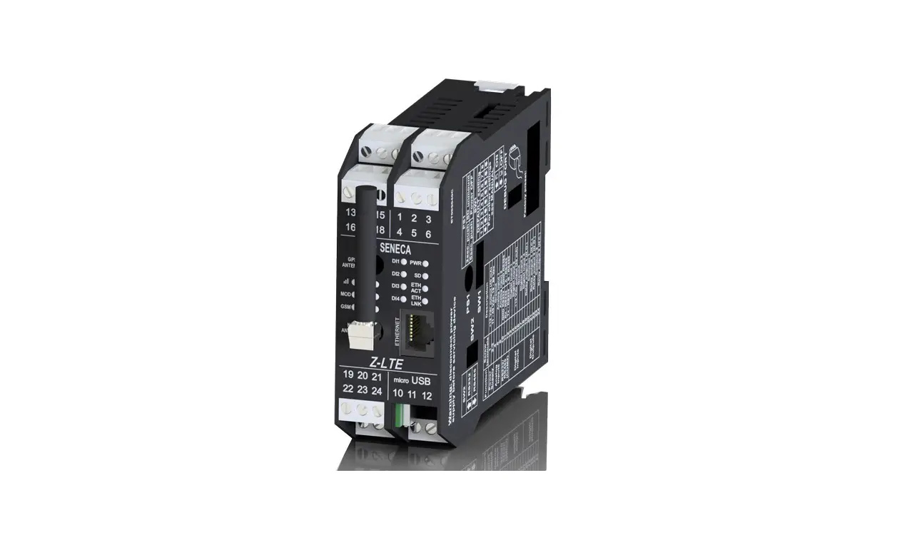
MODULE LAYOUT
Weight: 270 g;
Container: PA6, Black
SIGNALS VIA LED ON FRONT PANEL
LED | STATUS | LED meaning |
| PWR (Green) | ON | Log not active and status waiting for startup |
| Slow flashing | Log active and status in normal operation | |
| Flashing intermittently | Status in operation from backup battery (battery life 1 hour) | |
| Fast flashing | Error, see Webserver diagnostics | |
| Off | Device OFF | |
| ON | Maximum signal (Level 4) |
| Flashing | 3 flashes (Level 3) | |
| 2 flashes (Level 2) | ||
| 1 flash (Level 1) | ||
| Off | Minimum signal | |
| GSM (STATUS) (Yellow) | Short flash | Network search (200ms High / 1800 ms Low) |
| Long flash | Connected (1800 ms High / 200ms Low) | |
| Fast flashing | Data transfer in progress (125ms High / 125ms Low) | |
| On | Voice call | |
| MOD (Yellow) | On | Recorded on 4G network |
| Off | Connected to another network | |
| DO (1 and 2) (Red) | On | Digital output, relay energized |
| Off | Digital output, relay de-energised | |
| DI (from 1 to 4) (Red) | ON (NPN) | Digital input energised (GND closed contact) |
| ON (PNP) | Digital input energised (contact closed to +12 V) | |
| Off | Digital input not energized | |
| COM (Red) | Slow flashing | Activity in the RS485 or RS232 serial interface |
| Off | RS485 or RS232 serial interfaced not used | |
| Fast flashing | Timeout in the RS485 or RS232 communication | |
| SD (Red) | On | SD card inserted correctly |
| Slow flashing | Activity on SD card | |
| Fast flashing | SD card error | |
| Off | No SD card | |
| ETH LNK | Flashing | Connection on RJ45 active |
| ETH ACT | Flashing | Packet transit on Ethernet port |

TECHNICAL SPECIFICATIONS
| CERTIFICAZIONI | Z-LTE-WW Z-LTE-EU
https://www.seneca.it/products/z-lte-ww/doc/CE_declaration |
| INSULATION | 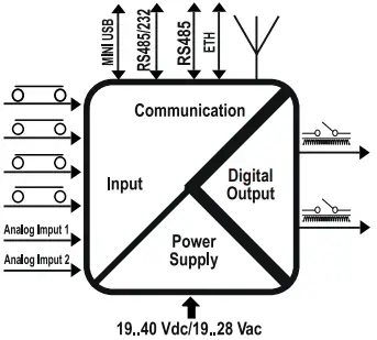
|
| ENVIRONMENTAL CONDITIONS | Temperature: -25– + 50°C / (-10– + 40°C if the internal UPS is used). Humidity: 30%– 90% non condensing. Storage temperature: -30– + 65°C / (-20– + 45°C < 6 months if the internal UPS is used). protection rating: IP20. |
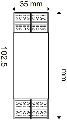
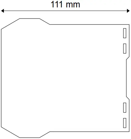
| ASSEMBLY | IEC EN60715, 35mm DIN rail in vertical position. |
| INTERNAL UPS | Rechargeable backup batteries. Duration: up to 1 hour. |
| CONNECTIONS | Removable 3-way screw terminals, 5 mm pitch for cable up to 2.5 mm², Rear IDC10, RJ45 socket, Micro USB socket and 2 SMA for 4G antenna and GPS antenna. |
| POWER SUPPLY | Voltage: 11 ÷ 40Vdc or 19 ÷ 28Vac 50 ÷ 60Hz. Absorption: 8W. |
| DIGITAL INPUTS | Number of channels 4. Configurable PNP or NPN. Voltage OFF<4V, ON>8V (Max. 24Vdc). Max frequency 30Hz. Absorbed current 3mA @ 12Vdc, 10mA @ 24Vdc. |
| TOTALIZERS | 4 x 32-bit totalizers on non-volatile memory |
| COUNTERS: | 4 x 32-bit resettable counters on non-volatile memory. |
| DIGITAL OUTPUTS | Number of channels 2. SPDT free contact relay. Max. voltage 250Vac. Max. current 2A. |
| ANALOGUE INPUTS | Number of channels 2. Configurable mA or Vdc. Voltage input 0 – 30V. precision 0.1% of Full Scale, impedance: 200 kohm. Current input 0– 20mA precision 0.1% of Full Scale, impedance: < 60 ohm. Input protection 40V / 25mA. Resolution 16 bit. |
| COMMUNICATION PORTS | RS485 COM1 on rear IDC10 connector, RS485 or RS232 on terminals M10-M11-M12, Ethernet 100 base T and micro USB on side socket. |
| 4G / LTE WORLD WIDE MODEM (Z-LTE-WW) | For further information, refer to the User Manual. |
| MODEM 4G (Z-LTE-EU) | For further information, refer to the User Manual. |
| GNSS | GPS / GLONASS / BeiDou(compass) / Galileo / QZSS |
| SD CARD SLOT | Push-push type for microSD and microSDHC 32GB max. |
| SIM CARD SLOT | Push-push type for miniSIM card 15 X 25 mm |
| CPU / S.O. | ARM 32bit, operating system: Real Time Multitasking, built-in Webserver and on microSD. |


IDC10 CONNECTOR
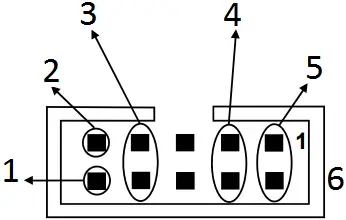
- RS485 B
- RS485 A
- RS485 GND
- Power Supply AC / +
- Power Supply AC / –
- 1 IDC 10
The illustration shows the meanings of the various IDC10 connector pins if signals are to be sent via them directly.
PROCEDURE FOR MODULE SWITCH-OFF
The module is equipped with an integrated UPS that allows it to remain on even in the absence of external power. To turn off the module, first disconnect the external power supply and then press the PS1 button on the right side of the module for at least 6 seconds. When the button is released, the PWR LED turns off to indicate that the module is turned off.
DIP – SWITCH SETTINGS
| DIP-SWITCHES | |||
| SW1 | Default settings: all DIP switches in OFF position. For more information see the USER MANUAL. | ||
| SW2 | RS232 or RS485 settings on terminals 10-11-12 (COM2 serial port) | ||
| RS232 | ON | ||
| RS485 | OFF | ||
ELECTRICAL CONNECTIONS
![]() CAUTION
CAUTION
On first start-up the module must be supplied without any interruptions for at least 72 hours to charge the internal batteries.
Switch the module off with the PS1 button before connecting inputs and outputs.
To meet the electromagnetic immunity requirements:
– use shielded signal cables;
– connect the shield to a preferential instrumentation earth system;
– separate shielded cables from other cables used for power installations (transformers, inverters, motors, etc…).
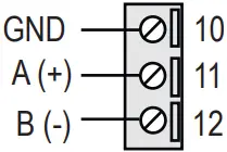
POWER SUPPLY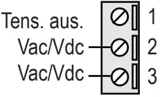 | SERIAL PORT RS485 SW2 = OFF
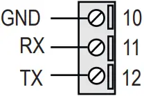
| SERIAL PORT RS232 SW2 = ON
|
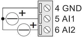
ANALOGUE INPUTS
| Voltage
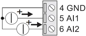
| Active sensor current (4 wires)
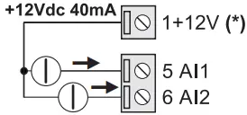
| Passive sensor current (2 wires)
(*) Not available without external power supply | The module has two analogue inputs that can be configured via software as voltage or current. For the configuration software, see the user manual. |
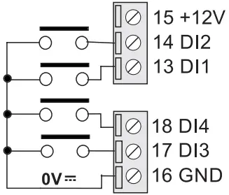
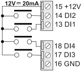
DIGITAL INPUTS
| NPN with internal power
| PNP with internal power
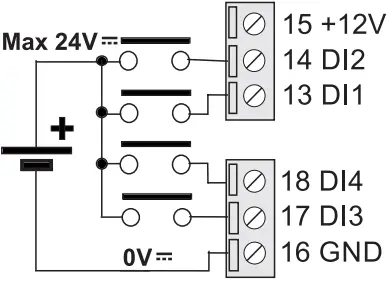
| PNP with external power
|
DIGITAL OUTPUTS
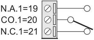 | 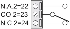 | The module has two digital outputs with free contacts. The figures show the internal relay contacts available. |
MI00514-10-EN INSTALLATION MANUAL


