![]()
User Manual
| Revision | V0.1 | ||
| Date | 2019-7-15 | ||
| Model Name | BL-M8822CU1 | ||
| Product Name | WiFi Module | ||
| Bilian Approve Field | |||
| Engineer | QC | Sales | |
| Customer Approve Field | |||
| Engineer | QC | Manufactory | Purchasing |
Revision history
| Date | Document Revision | Product Revision | Description |
| 2019/07/15 | 0.1 | V0.1 | Preliminary release |
Introduction
General Description
BL-M8822CU1 is a highly integrated module that was built in a 2*2 dual-band wireless LAN radio and Bluetooth radio. It combines a WLAN MAC, a 2T2R capable WLAN base band, and RF in a single chip. It supports IEEE 802.11a/b/g/n/ac standard and provides the highest PHY rate up to 867Mbps, offering featurerich wireless connectivity and reliable throughput from an extended distance.
Note: The above pictures are for reference only
Features
- Operating Frequencies : 2.4~2.4835GHz and 5.15~5.85GHz
- Host Interface is USB
- IEEE Standards : IEEE 802.11a/b/g/n/ac
- Wireless data rate can reach up to867Mbps
- Connect to external antenna through IPEX connectors
- Power Supply: VBAT 3.3V±0.3V main power supply
Applications
- MID
- IP Camera
- STB
- Smart TV
- E-book
- Other devices which need to be supported by wirelessnetwork
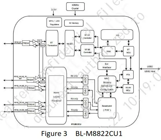
Functional Block Diagram
Product Technical Specifications
General Specifications
| Item | Description |
| Product Name | BL-M8822CU1 |
| Main Chip | RTL8822CU-CG |
| Host Interface | USB2.0 for WiFi and Bluetooth |
| IEEE Standards | IEEE 802.11a/b/g/n/ac |
| Operating Frequencies | 2.4-2.4835GHz, 5.180-5.835 GHz |
| Modulation | WiFi : 802.11b DSSS: CCK, DQPSK, DBPSK 802.11g OFDM: 64-QAM,16-QAM, QPSK, BPSK 802.11n OFDM: 64-QAM,16-QAM, QPSK, BPSK 802.11ac OFDM: 256-QAM, 64-QAM,16-QAM, QPSK, BPSK |
| Working Mode | Infrastructure, Ad-Hoc |
| Wireless Data Rate | WiFi: 802.1lb: 1, 2 ,5.5,11Mbps, 802.11a: 6,9,12,18,24,36,48,54Mbps, 802.11g:6,9,12,18,24,36,48,54Mbps, 802.11n-2.4/5G HT20: MCSO-15, 6.5-144.4Mbps, 802.11n-2.4/5G HT40: MCSO-15, 13″300Mbps, 802.11ac-VHT20:MCS0-8 VHT40, 80:MCS0-9 ,reach up to 867Mbps |
| Rx Sensitivity | -95dBm (Min) |
| Antenna Type | PCB Antenna |
| Dimension(L*W*H) | 27*17.8*3.0mm (LxWxH) I olerance:+/-0.15mm |
| Clock Source | 40MHz |
| Working Temperature | -10t to +70 C |
| Storage Temperature | -40t to +85 `C |
wifi DC Power Consumption
| VDD=3.3V, Ta = 25 °C, unit: mA | ||||
| Supply current | Typ | Max | ||
| RX sense mode(No Link) | 60 | 90 | ||
| 802.11b | 1Mbps | 11Mbps | ||
| Supply current | Typ. | Max. | Typ. | Max. |
| Continuous TX mode | 230 | 244 | 198 | 256 |
| RX mode | 62 | -4 | 65 | 75 |
| 802.11g | 6Mbps | 54Mbps | ||
| Supply current | Typ. | Max. | Typ. | Max. |
| Continuous TX mode | 371 | 606 | 229 | 4X2 |
| RX mode | 62 | 73 | 62 | 77 |
| 802.11n HT20 | MCSO | MCS7 | ||
| Supply current | Typ. | Max. | Typ. | Max. |
| Continuous TX mode | 371 | 596 | 223 | 4-2 |
| RX mode | 61 | 75 | 62 | 78 |
| 802.11n HT20 | MCS 8 | MCS15 | ||
| Supply current | Typ. | Max. | Typ. | Max. |
| Continuous TX mode | 279 | 4in, | 161 | 401 |
| RX mode | 62 | 73 | 62 | 75 |
| 802.11n11140 | MCSO | MCS7 | ||
| Supply current | Typ. | Ma. | Typ. | Max. |
| Continuous TX mode | 332 | 604 | 189 | 476 |
| RX mode | 60 | 74 | 61 | 75 |
| 802.11n H190 | MCS 8 | M4515 | ||
| Supply current | Typ. | Max | Typ. | Max. |
| Continuous TX mode | 242 | 404 | 143 | 410 |
| RX mode | 63 | 75 | 62 | 73 |
| 802.11a | 6Mbps | 54Mbps | ||
| Supply current | Typ. | Max | Typ. | Max. |
| Continuous TX mode | 459 | 712 | 283 | 762 |
| RX mode | 60 | 74 | 58 | 72 |
| 802.11n HT20(SG1 | MCSO | MCS7 | ||
| Supply current | Typ. | Max. | Typ. | Max. |
| Continuous TX mode | 458 | 734 | 277 | 754 |
| RX mode | 62 | 77 | 60 | 71 |
| 802.11n HT20{5G) | MCS8 | MC515 | ||
| Supply current | Typ. | Max. | Typ. | Max. |
| Continuous TX mode | 458 | 734 | 277 | 754 |
| RX mode | 62 | 72 | 60 | 71 |
| 802.13n H190(5G) | MCSO | MC57 | ||
| Supply current | Typ. | Max | Typ. | Max. |
| Continuous TX mode | 416 | 722 | 230 | 728 |
| RX mode | 61 | 75 | 59 | 70 |
| 802.11n H140(5G) | MCS8 | MCS15 | ||
| Supply current | Typ. | Max. | Typ. | Max. |
| Continuous TX mode | 314 | 624 | 182 | 672 |
| RX mode | 60 | 73 | 58 | 69 |
| 802.11acV1111015G) | MCSO | MCS9 | ||
| Supply current | Typ. | Max. | Typ. | Max. |
| Continuous TX mode | 361 | 744 | I90 | 718 |
| RX mode | 58 | 71 | 61 | 74 |
WiFi RF Specification
| TX Power & EVM | WIFi-2.4G: 18.0+1.5dBm&<-15dB@11b 11Mbps 16.0+1.5dBm&<-28dB@11g 54Mbps 16.0+1.5dBm&<-28dB@11n-HT20/40-MCS7 |
| WIiFi-SG: 16.0 + 2dBm&<-28dB@11a 54Mbps 15.0+2dBm&<-28dB@11n-HT20/40-MCS7 14+ 2dBm&<-32dB@11ac-HT80-MCS9 | |
| Receiver Minimum Input Sensitivity@PER | WIFi-2.4G: 11b 1Mbps: -94dBm@PER<8%; 11b 11Mbps:-86dBm@PER<8%; 11g S4Mbps:-74dBm@PER<10%; 11n-HT20-MCS7:-70dBm@PER<10%; 11n-HT40-MCS7:-68dBmM@PER<10%; WIFI-5SG: 11a 54Mbps:-72dBm@PER<10%; 11n-HT20-MCS7:-68dBm@PER<10%; 11n-HT40-MCS7:-66dBmM@PER<10%; 11ac-HT80-MCS9:-S8dBmM@PER<10%; |
ESD CAUTION: Although this module is designed to be as robust as possible, Electrostatic Discharge (ESD) can damage this module. It must be protected from ESD at all times and handled under the protection of ESD.
Pin Assignments
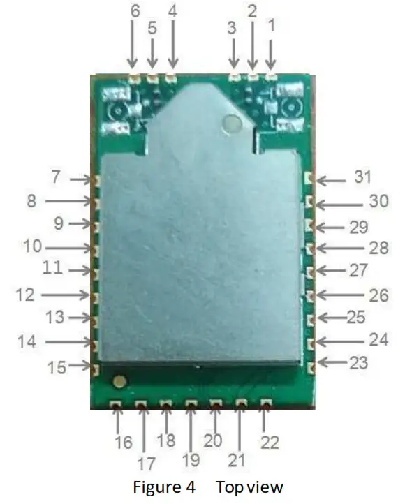
| PIN | Function | Description |
| 1 | GND | Ground connections |
| 2 | WL ANTI | WLAN_ANT(NC) /use IPEX connector |
| 3 | GND | Ground connections |
| 4 | GND | Ground connections |
| 5 | WL ANTO | WLAN_ANT(NC) /use IPEX connector |
| 6 | GND | Ground connections |
| 7 | GND | Ground connections |
| 8 | NC | No connection(floating) |
| 9 | NC | No connection(floating) |
| 10 | GND | Ground connections |
| 11 | GPIOS | For SPI flash data line 5101 use (NC) |
| 12 | GPIO6 | WLAN wake up host /For SPI flash data line $102 use (NC) |
| 13 | GND | Ground connections |
| 14 | NC | No connection(floating) |
| 15 | NC | No connection(floating) |
| 16 | NC | No connection(floating) |
| 17 | NC | No connection(floating) |
| 18 | GND | Ground connections |
| 19 | HSDP | USB 2.0 differential line |
| 20 | HSDM | USB 2.0 differential line |
| 21 | VBAT | 3.3V Main Power Supply |
| 22 | RESET | System reset signal active low |
| 23 | BT_WAKE_HOST | BT wake up host |
| 24 | GPIO7 | HOST wake up WLAN /SPI flash data line 5103(NC) |
| 25 | HOST WAKE BT | HOST wake up BT |
| 26 | EECS | SPI flash chip select pin(NC) |
| 27 | EESK | SPI flash clock pin(NC) |
| 28 | GPIO4 | SPI flash data line S100(NC) |
| 29 | GND | Ground connections |
| 30 | BT ANT | BT ANT |
| 31 | GND | Ground connections |
Typical Application Circuit
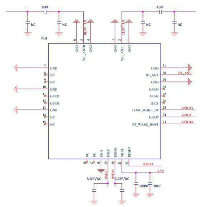
Figure 5
NOTE
a. RF traces need to keep 50 ohm impedance.
b. PIN_22 actives low USB system reset.
c. VBAT 3.3V for main power.
Mechanical Specifications
Module dimension: Typical ( L*W *H): 27mm*17.8mm*3.0mm Tolerance : +/-0.15mm
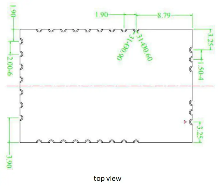
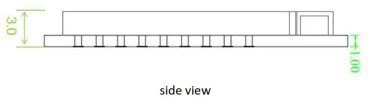
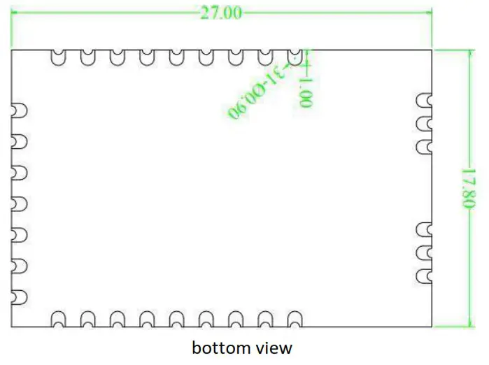 Figure 6 Module dimension (top , side and bottom view)
Antenna specification
Antenna Type:
Ant0: PCB Antenna
Ant1: PCB Antenna
Antenna Gain:
Ant0:
2412MHz to 2462 MHz: 6.07 dBi
5150 MHz to 5250 MHz: 5.02 dBi
5250 MHz to 5350 MHz: 6.15 dBi
5470 MHz to 5725 MHz: 8.46 dBi
5725 MHz to 5850 MHz: 9.23 dBi
Ant1:
2412MHz to 2462 MHz: 5.15 dBi
5150 MHz to 5250 MHz:6.45 dBi
5250 MHz to 5350 MHz: 6.48 dBi
5470 MHz to 5725 MHz: 7.26 dBi
5725 MHz to 5850 MHz: 5.38 dBi
Others
Package Information
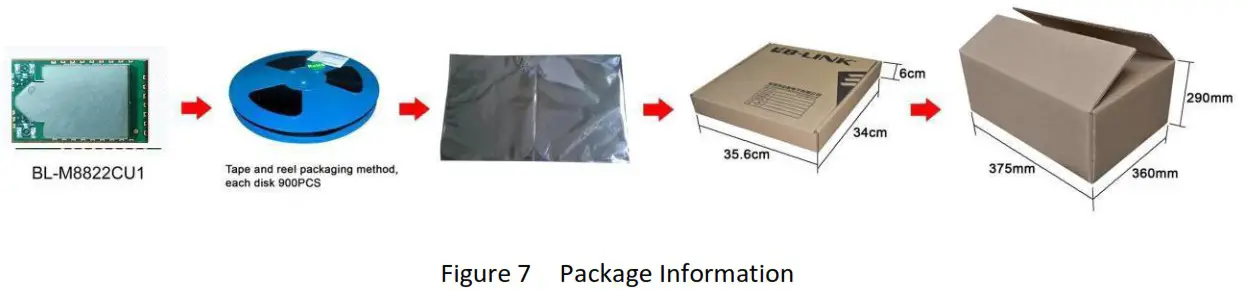
Storage Temperature and Humidity
- Storage Condition: Moisture barrier bag must be stored under 30, humidity under 85% RH. The calculated shelf life for the dry packed product shall be a 12 months from the bag seal date. Humidity indicator cards must be blue, <30%.
- Products require baking before mounting if humidity indicator cards reads > 30% temp < 30, humidity < 70% RH, over 96 hours. Baking condition: 125, 12 hours. Baking times: 1 time.
Recommended Reflow Profile
Reflow soldering shall be done according to the solder reflow profile,Typical Solder Reflow Profile is illustrated in Figures 15. The peak temperature is 245ºC.
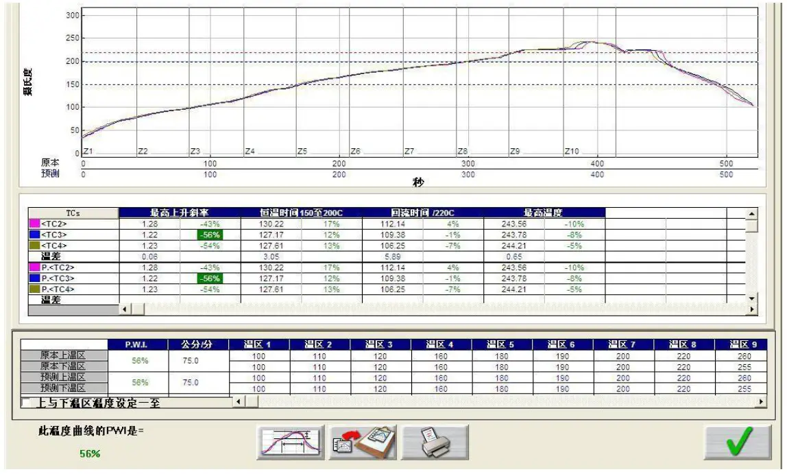
Figure 7 Typical Solder Reflow Profile
U.S. FCC Part 15 Regulatory Information
This device complies with part 15 of the FCC Rules. Operation is subject to the following two conditions: (1) This device may not cause harmful interference, and (2) this device must accept any interference received, including interference that may cause undesired operation.
Any Changes or modifications not expressly approved by the party responsible for compliance could void the user’s authority to operate the equipment.
Note: This equipment has been tested and found to comply with the limits for a Class B digital device, pursuant to part 15 of the FCC Rules. These limits are designed to provide reasonable protection against harmful interference in a residential installation. This equipment generates, uses and can radiate radio frequency energy and, if not installed and used in accordance with the instructions, may cause harmful interference to radio communications. However, there is no guarantee that interference will not occur in a particular installation. If this equipment does cause harmful interference to radio or television reception, which can be determined by turning the equipment off and on, the user is encouraged to try to correct the interference by one or more of the following measures:
- Reorient or relocate the receiving antenna.
- Increase the separation between the equipment and receiver.
- Connect the equipment into an outlet on a circuit different from that to which the receiver is connected.
- Consult the dealer or an experienced radio/TV technician for help.
This modular complies with FCC RF radiation exposure limits set for an uncontrolled environment. This transmitter must not be co-located or operating in conjunction with any other antenna or transmitter. This modular must be installed and operated with a minimum distance of 20 cm between the radiator and the user’s body.
The device shall automatically discontinue transmission in cases of absence of information to transmit, or operational failure. Then it will scan the available radio signals. If this signal is connected before, it will be automatically connected, otherwise manual connections will be necessary.
The devices must be installed and used in strict accordance with the manufacturer’s instructions as described in the user documentation that comes with the product.
The module must be installed in Host. In the event that these conditions cannot be met (for example certain laptop configurations or co-location with another transmitter), then the FCC authorization is no longer considered valid and the FCC ID cannot be used on the final product. In these circumstances, the OEM integrator will be responsible for re-evaluating the end product (including the transmitter) and obtaining a separate FCC authorization.
This device complies with FCC part 15C: 15.247 and 15.407.
This device and its antenna(s) must not be co-located or operating in conjunction with any other antenna or transmitter. The module should be installed at a minimum distance of 20 cm away from a person nearby. The host product manufacturer should state this information to the host instruction manual.
Trace antenna designs – not applicable.
Any final host product with the modular transmitter installed should be under test according to guidance given in KDB 996369 D04. To enter test mode for module, secure CRT command is necessary. When something wrong happens in configuring test modes for host product with module, host product manufacturer should coordinate with module manufacturer for technical support. It is recommended that some investigative measurements should be taken to confirm that host product with module installed does not exceed the spurious emissions limits or band edge limits.
The modular complies with FCC authorised for the specific rule parts (FCC Part 15.247 and 15.407) list on the grant, and that the host product manufacturer is responsible for compliance to any other FCC rules that apply to the host not covered by the modular transmitter grant of certification. The final host product still requires Part 15 subpart B compliance testing with the modular transmitter installed when contains digital circuity.
The device is going to be operated in 5150~5350MHz frequency range. It is restricted indoor environment only.
The end product must carry a label stating “Contains FCC ID: SVNM8822CU1” or shall use e- labeling.
Manufacturer’s name and address: SHENZHEN BILIAN ELECTRONIC CO.,LTD 10~11/F, Building 1A, Huaqiang idea park, Guangming district, Shenzhen. Guangdong, China


