
![]() Dadoutek Electronics DB809S BLE 5 Module
Dadoutek Electronics DB809S BLE 5 Module
Instruction Manual
| Version | Update Time | Editor |
| VI.00 | 2019-3-15 | Alan Jiao |
| VI.10 | 2019-4-17 | Jack Wang |
| V1.11 | 2019-4-22 | Jack Wang |
| V1.12 | 2020-6-16 | Allen. Hu |
| VI.13 | 2020-7-10 | Joe.Zhou |
| V1.14 | 2020-8-17 | Allen Hu |
Product Introduction
Product Overview
DB809S is made by nRF52805 which is the baseline member of the nRF52 Series SoC family. It is built around an ARM® Cortex™-M4 CPU running at 64 MHz. It meets the challenge of bringing Bluetooth 5 feature sets and protocol concurrency to applications at a price point that makes adding Bluetooth 5 connectivity to an application compelling. It is an ideal candidate for less complex applications and also as a Bluetooth 5 connectivity processor in larger applications.
DB809S is an SMD package, and the rapid production of can be realized through the standard SMT equipment. It can give customers a high-reliability connection, especially suitable for automation, large-scale modern mode of production, low cost, convenient application in all kinds of Internet of things terminal hardware.
Detail Param
Performance
Form 1: Performance
| Module | DB809S |
| Soc | nRF52805 WLCSP |
| FLASH | 192KB |
| RAM | 24KB |
| VDD | 1.7V to 3.6V |
| PIN Num | 15 |
| Working FRQ | 2402MHz-2480MHz (BLE)/2360MHz-2500MHz(nRF Private mode) |
| GPIO | 10 |
| ADC | 12-bit, 200 kbps, 2 channels |
| PWM | 4 Channels |
| PDM | 1 |
| TIMER/RTC | 3 x 32bit(Count mode)/2 |
| SPI/I2C/UART | 1 (Master or Slave mode)/ 1 (Master or Slave mode)/1 |
| AES | Hardware |
| RNG | 1 |
| Comparator | 64 level* 2 Channels |
| WatchDog | 1 |
| TX Power | -20 to +4 dBm, 4db steps |
| RF PHY | 1Mbps, 2Mbps BLE mode/1M, 2Mbps Nordic nRF Private mode |
| Current (Chip reference) | TX: 4.6 mA peak current (0 dBm) RX: 4.6 mA peak current 0.3uA (3V VDD) in System OFF mode, no RAM retention |
| Working Temperature | -40°C851: |
| Storage Temperature | 22°C281: |
| Package Size | 10.5*16*3mm |
Mechanical specifications
Picture 1 is the PCB mechanical specifications of the module.
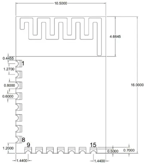
Picture 1: PCB Mechanical Specifications dimensions in millimeters
Form 2
| Length | Width | PCB Height | PAD Size (Bottom) | PIN Gap |
| 10.5mm | 16mm | 2.33mm | 0.7mm*0.8mm | I.27mm |
PIN Description
PIN | PIN On nRF52 | Description |
| 1 | GND | GND |
| 2 | STUDIO | Serial wire debug I/O for debugging and programming |
| 3 | SWCLK | Serial wire debug clock input for debugging and programming |
| 4 | P0.21/PRESET | Digital I/O / Configurable as pin reset |
| 5 | P0.20 | Digital I/O |
| 6 | P0.18 | Digital I/O |
| P0. 16 | , Digital I/O | |
| s | P0.12 | Digital I/O |
| P0.14 | Digital I/O | |
| 10 | P0.05/AIN3 | Analog input /Digital I/O |
| II | P0.04/AIN2 | Analog input /Digital I/O |
| 12 | P0.01/XL2 | General-purpose I/O Connection for 32. 768 kHz crystal (LFXO) |
| 13 | P0.00/XL1 | General-purpose I/O Connection for 32. 768 kHz crystal (LFXO) |
| 14 | VDD | 1.7 V 13.6V (Recommended voltage range) |
| 15 | GND | GND |
Note: Input voltage higher than VCC will destroy the module.
Soldering Reflow Guidelines
Form 4 and picture 2 are reflow conditions and profiles.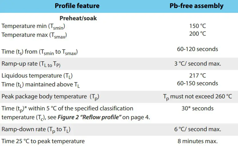
Form4: Reflow conditions
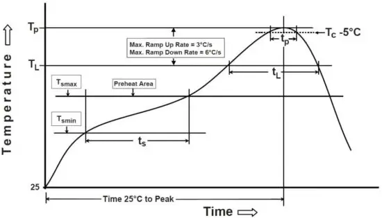 Picture 2: Reflow profile
Attentions
- This module contains CMOS devices, that need to be protected from ESD.
- Module needs to connect GND well, to reduce parasitic inductance.
- If the module needs reflow, pay attention to the reflow profile.
- The area below the ANT of this module, should not use polygon.
- ANT of this module should be far away from another circuit.
- The module should be placed as far as possible away from the other low-frequency circuits or digital circuits.
- Module is plugged into a power supply for recommending the use of magnetic beads in isolation.
- If there are other internal band wireless modules in your product, frequency should be reasonable planning, take the shielding measures, such as reducing the influence of harmonic interference and intermodulation interference.
Sales And Service Network
Headquarter
Shenzhen Headquarter
Add: Rm.1502, FIYTA Tech Building,#002 No.1 SouthernRd, Hi-Tech, Nanshan District, Shenzhen 518057, P.R.China
Tel:86-755-86018818
Fax:86-755-86018808
North China
Beijing Office
Add :Room1006,QuantumPlaza,No.23ZhiChunRoad, Haidian District, Beijing
Tel:86-10-82358601/2/3/4
Fax:86-10-82358605
East China
Shanghai Office
Add :Rm.2005,MingshenCenterBuilding,No.3131,KaixuanRoad,XuhuiDistrict,Shanghai200030,P.
R.China
Tel:86-21-54071701
Fax:86-21-54071702
Southwest China
Chengdu Office
Add: Room1402,Bldg#2,ShuduCenter,No.138,TianfuNo.2Street,MidSection,TianfuAvenue,HighTechDistrict,ChengduCity
Tel:86-28-85355251
Fax:86-28-85350890
This equipment has been tested and found to comply with the limits for a Class B digital device, pursuant to part 15 of the FCC Rules. These limits are designed to provide reasonable protection against harmful interference in a residential installation. This equipment generates, uses, and can radiate radio frequency energy and, if not installed and used in accordance with the instructions, may cause harmful interference to radio communications.
However, there is no guarantee that interference will not occur in a particular installation. If this equipment does cause harmful interference to radio or television reception, which can be determined by turning the equipment off and on, the user is encouraged to try to correct the interference by one or more of the following measures:
- Reorient or relocate the receiving antenna.
- Increase the separation between the equipment and receiver.
- Connect the equipment into an outlet on a circuit different from that to which the receiver is connected.
- Consult the dealer or an experienced radio/TV technician for help.
Caution: Any changes or modifications to this device not explicitly approved by the manufacturer could void your authority to operate this equipment.
This device complies with part 15 of the FCC Rules. Operation is subject to the following two conditions: (1) This device may not cause harmful interference, and (2) this device must accept any interference received, including interference that may cause undesired operation.
The device has been evaluated to meet general RF exposure requirements
This equipment complies with FCC radiation exposure limits set forth for an uncontrolled environment.
This equipment should be installed and operated with a minimum distance of 20cm between the radiator & your body.


