
PLEASE READ BEFORE STARTING INSTALLATION!
User Manual
Performance upgrade
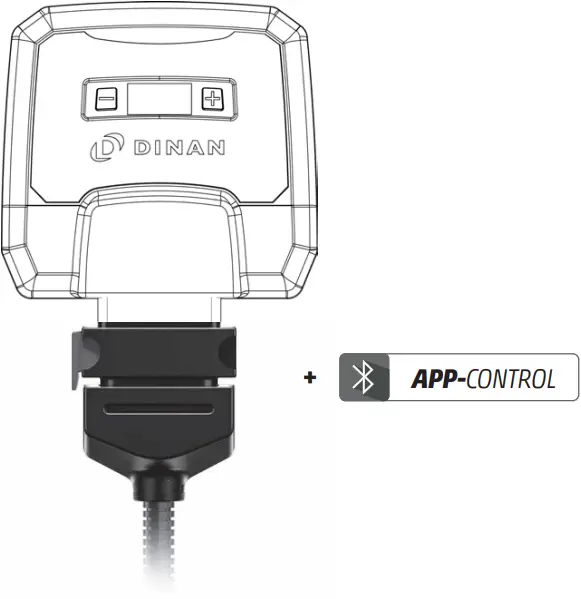
D440-0133: DINANTRONICS X; S63 A

Overview and explanation of symbols
![]() Warnings and important information – please read!
Warnings and important information – please read!![]() General information on installation and use
General information on installation and use![]() Tips to assist installation and use
Tips to assist installation and use
1 Scope of Delivery
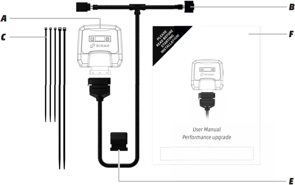
A Performance upgrade
calibrated specifically for your vehicle
B Wiring harness
automobile-grade, compatible with your vehicle (1)
C Cable ties
to mount the Performance upgrade and the wiring harness
2 x long cable ties
3 x short cable ties
E Deactivation plug
returns your engine to stock tune
F User Manual
installation and operation
(1) Picture may differ from delivered product.
2 Overview of the performance upgrade
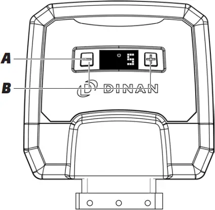

A Digital User Interface for controlling the performance upgrade.
B +/- buttons for changing the mapping (see Fine tuning)
C Power ON light; lights only when the vehicle ignition is on and power is being supplied to the performance upgrade.
D Display showing mapping selected (see Fine tuning).
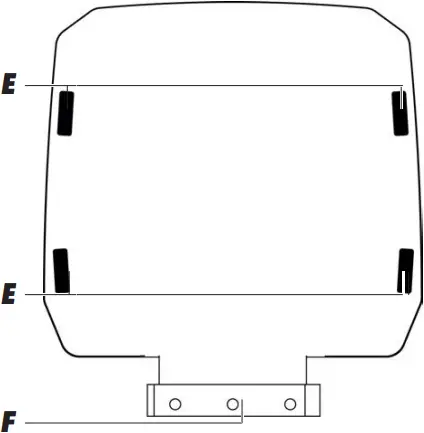
E Slots for cable ties to mount the product
F FCI plug for connecting to the vehicle’s wiring.
3 Installation
Step 1 – Preparation
![]() Before installing the tuning module, please wait for your engine to cool down. Otherwise there is a risk of sustaining burns.
Before installing the tuning module, please wait for your engine to cool down. Otherwise there is a risk of sustaining burns.
 Put on the parking brake (emergency brake) before starting installation.
 If an alarm system is fitted: disable the alarm before starting installation. For further instructions, check the manual of the car manufacturer.
![]() Some cars will not lock completely if the hood is open and electrical consumers are still active. If this is the case with your car, push the hood catch over manually, lock the car again and wait ca. 15 minutes. When you have finished the installation, do not forget to release the catch again by pulling the hood release lever.
Some cars will not lock completely if the hood is open and electrical consumers are still active. If this is the case with your car, push the hood catch over manually, lock the car again and wait ca. 15 minutes. When you have finished the installation, do not forget to release the catch again by pulling the hood release lever.
 Turn the ignition off and lock your vehicle. For cars with “Keyless Go“: after locking the car, place the key out of signal range (about 11 yards or 10 meters from the car).
 After locking the vehicle, wait about 10 minutes before starting Step 2, as all current consumers must have switched themselves off.
 | Generally speaking, you do not require special tools to perform the installation. If you need a tool, we will tell you when you get to the relevant step in these instructions. You will probably find wire cutters useful for clipping off the loose ends of cable ties. |
|
![]() If you do not wait for at least 10 minutes, electrical voltage and signal flow may still be present in the connections. Detaching the connectors while electronic signals still flow, may damage your vehicle.
If you do not wait for at least 10 minutes, electrical voltage and signal flow may still be present in the connections. Detaching the connectors while electronic signals still flow, may damage your vehicle.
![]() Never turn on the ignition while connectors are disconnected. Risk of check light on the dashboard!
Never turn on the ignition while connectors are disconnected. Risk of check light on the dashboard!
![]() Disconnecting the battery may damage your vehicle. Do not disconnect the battery at any time, if not otherwise prompted in the instruction manual.
Disconnecting the battery may damage your vehicle. Do not disconnect the battery at any time, if not otherwise prompted in the instruction manual.
![]() If stock parts must be dismounted, please check vehicle manufacturer manual for tightening torques.
If stock parts must be dismounted, please check vehicle manufacturer manual for tightening torques.
![]() To avoid damages at electronic vehicle components, you have to be sure that you have done all necessary methods for electrostatic discharge.
To avoid damages at electronic vehicle components, you have to be sure that you have done all necessary methods for electrostatic discharge.
![]() Tuning modules are developed, produced and tested for vehicles in stock condition.
Tuning modules are developed, produced and tested for vehicles in stock condition.
![]() Using 3rd-party on-board diagnostic (OBD) scan tools may damage your vehicle. Do not use them.
Using 3rd-party on-board diagnostic (OBD) scan tools may damage your vehicle. Do not use them.
Step 2 – Removing the engine cover
- Remove the engine cover and place it next to the car.
| Generally speaking, you do not require special tools to perform the installation. If you need a tool, we will tell you when you get to the relevant step in these instructions. You will probably find wire cutters useful for clipping off the loose ends of cable ties. |
![]() Using wrong tools or too much force may damage parts of your vehicle. Use appropriate tools. Do not use too much force.
Using wrong tools or too much force may damage parts of your vehicle. Use appropriate tools. Do not use too much force.
Step 3 – Connector locations
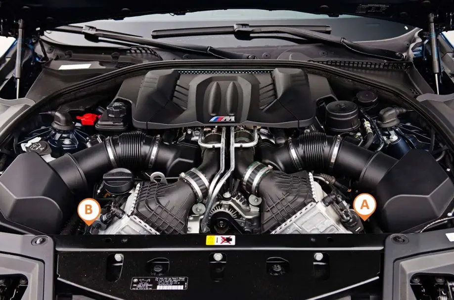
View of longitudinally mounted engine
(A) turbo boost pressure sensor
(B) turbo boost pressure sensor
Step 4 – Connection to turbo boost pressure sensor
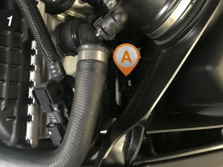
- To begin, locate the turbo boost pressure sensor in your engine bay.
Setup illustration
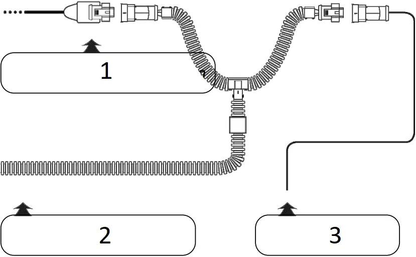
- Turbo boost pressure connection
- Cable from the tuning module
- Cable with disconnected stock connector
- Disconnect the plug from turbo boost pressure sensor.
| If you experience difficulties disconnecting the turbo boost pressure sensor, see Detaching the Connector Correctly (separate document) for assistance. |
- Now connect the end of the wiring harness marked “A” to the disconnected connector and the other end to the sensor.
 | Make sure that the plug’s locking clip engages again. You should hear a sharp CLICK. |
Step 5 – Connection to turbo boost pressure sensor
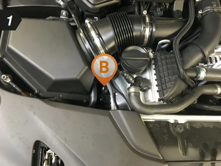
- To begin, locate the turbo boost pressure sensor in your engine bay.
Setup illustration

- Turbo boost pressure connection
- Cable from the tuning module
- Cable with disconnected stock connector
- Disconnect the plug from turbo boost pressure sensor.
| If you experience difficulties disconnecting the turbo boost pressure sensor, see Detaching the Connector Correctly (separate document) for assistance. |
- Now connect the end of the wiring harness marked “B” to the disconnected connector and the other end to the sensor.
| Make sure that the plug’s locking clip engages again. You should hear a sharp CLICK. |
Step 6 – Connecting and first function test
1 Disconnect the deactivation plug from the wiring harness
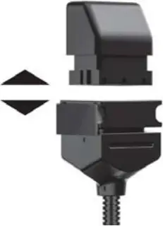
2 Connecting to the wiring harness

 |
|
3 Carrying out function test
- Position the tuning module and the wiring harness safely in the engine bay.
- Switch the ignition on. DO NOT start the engine.
- Check for the following:
– Control lights on the dashboard light up and go out as normal
– The Power ON light on the Digital User Interface of your tuning module lights up (see Overview) - If all the above happens, you can start the engine. It should start as normal and should react to the throttle when idling.
- Switch off the engine and ignition.
|
Step 7 – Fixing the tuning module and wiring harness
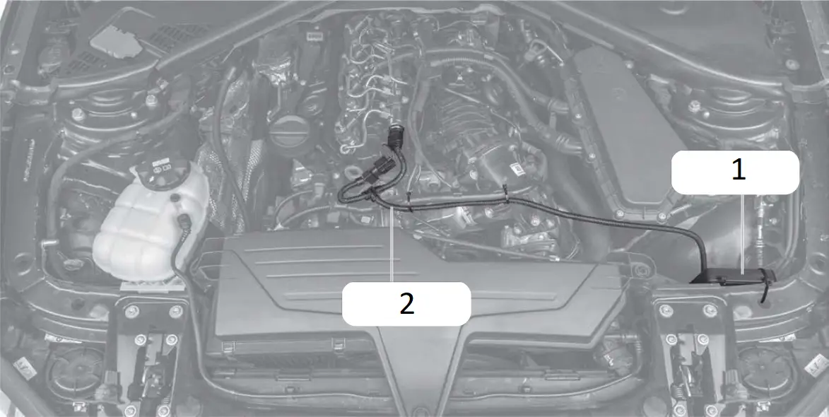
- Tuning module
- Wiring harness
- Before fixing the tuning module in place in the engine bay, ensure that the wiring harness can also be routed and fixed securely without putting it under excessive tension.
- Route the cable along a suitable path (for example, along existing wiring harness) and then fasten it using the supplied cable ties.
|
|
|
|
Step 8 – Completing the installation
- Re-attach the cover of your engine and close the bonnet.
- The installation process is now complete and your tuning module is ready for use.
- Take your car for a test drive.
Last step – Pair the tuning module with your smartphone
According to your operating system (Android and Apple), the steps for connecting the tuning module and your smartphone may vary lease find the most important steps below In general, you should follow the instructions given by your smartphone for the connection.
|
1 Download the free DINANTRONICS X app by scanning the appropriate QR code for your device below.


2 Switch on the ignition of your car. Do not start the engine.
3 Activate the Bluetooth function of your smartphone. 
4 Open the DINANTRONICS X app. 
5 With opening the DINANTRONICS X app for the first time, the installation dialogue for chip tuning by tuning module is shown. Touch ADD PRODUCT and follow the instructions given by your smartphone.

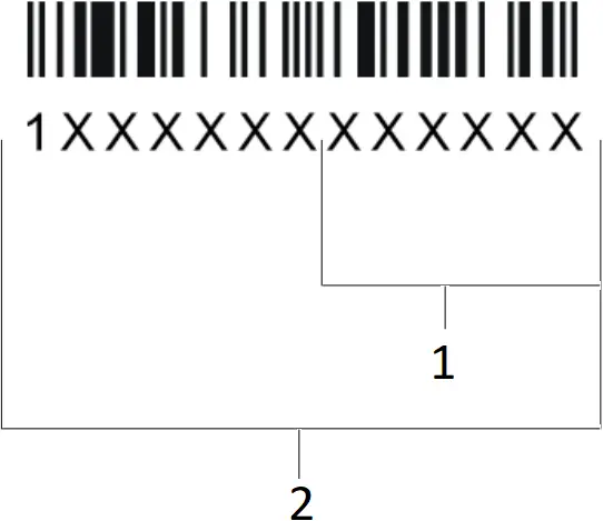
6 You can enter the serial number by hand (touch MANUALLY) or with the barcode scanner of the camera (touch ![]() ). Confirm the entry with NEXT.
). Confirm the entry with NEXT.
| The 13-digit serial number is located on the FCI connector of the tuning module. The Bluetooth PIN consists of the last 6 digits of the serial number. Example:
|

 | Having trouble with connecting your tuning module and your phone’s Bluetooth? *Follow these steps one by one until the pairing is complete:
|
7 As soon as the connection is set up, the installation is completed.
4 Fine tuning
The performance upgrade has been calibrated specifically for the engine in your car, and further adjustment is generally not necessary in order to get the best performance. However, performance tolerances or the condition of the engine sometimes mean that Fine tuning is needed after installing the performance upgrade.
The Digital User Interface of the performance upgrade (see Overview of the performance upgrade) lets you carry out the Fine tuning yourself to get the best from your Dinan-enhanced engine
Fine tuning may be necessary if the following occurs
A Engine idles more roughly than in stock tune.
| Engine runs roughly, knocks or “pinks” under load, or the engine warning light comes on. |

- Mapping step -1
- Mapping step +1
![]() The Fine tuning mappings can be changed using the +/- buttons only when the ignition is switched on but without the engine running.
The Fine tuning mappings can be changed using the +/- buttons only when the ignition is switched on but without the engine running.
- Mapping 5 is the factory setting.
- First activate Mapping 1.
- Take your car for a test drive. If the engine performs as smoothly as you want, i.e. no hesitation or knocking, please activate Mapping 2 and go for another test drive.
- If the engine still performs as smoothly as you want, repeat the previous step.
- If the engine does not perform as smoothly as you want with one of the mappings, go back to the previous mapping – this is the right one for your engine.
| If your engine does not run smoothly with any of the mappings or if the engine control light is permanently on after making all the adjustments (and after switching the ignition off and waiting 15 minutes), please contact our Customer Service (see Contact for details). |
B Making the enhanced performance more noticeable
| If the driver does not experience the extra performance, it means the driver cannot feel the difference from stock tuning. |
- Mapping step -1
- Mapping step +1
![]() The Fine tuning mappings can be changed using the +/- buttons only when the ignition is switched on but without the engine running.
The Fine tuning mappings can be changed using the +/- buttons only when the ignition is switched on but without the engine running.
- Mapping 5 is the factory setting.
- First activate Mapping 6.
- Take your car for a test drive. Activate Mapping 7 only if you do not experience the enhanced performance strongly enough.
- If the engine does not perform as smoothly as you want, activate the next mapping down the scale (e.g. from 6 to 5).
![]() For optimum performance, please use 93 octane fuel when driving in Mapping 6 or 7 (gasoline cars only).
For optimum performance, please use 93 octane fuel when driving in Mapping 6 or 7 (gasoline cars only).
|
|
5 Trouble Shooting
If the Performance upgrade does not function as it should, you can find some initial assistance here. If the suggestions here do not solve the problem, please contact our Customer Service (see Contact).
![]() If you do not wait for at least 10 minutes after locking your car, electrical voltage and signal flow may still be present in the connections. Detaching the connectors while electronic signals still flow, may damage your vehicle.
If you do not wait for at least 10 minutes after locking your car, electrical voltage and signal flow may still be present in the connections. Detaching the connectors while electronic signals still flow, may damage your vehicle.
![]() Using 3rd-party on-board diagnostic (OBD) scan tools may damage your vehicle. Do not use them. Dinan is not liable for damages caused by any 3rd party OBD system.
Using 3rd-party on-board diagnostic (OBD) scan tools may damage your vehicle. Do not use them. Dinan is not liable for damages caused by any 3rd party OBD system.
| Description of problem | What to do |
| No extra performance or performance not noticeable enough I am not satisfied with the performance level of my vehicle. |
|
| Knocking/ rattling The engine knocks or rattles (diesel engine) more under load. It runs less smoothly than in stock tune. |
|
| Jolting With the performance upgrade installed, my car jolts, stutters or hesitates in situations where it did not before. |
|
| Quality of gear shift reduced The shift behaviour and/or the shift quality has worsened since the installation of the performance upgrade. The gearbox sometimes cannot seem to find the right gear. |
|
| Engine fault light or other warning light comes on and stays on after installing the performance upgrade. A warning light on the dashboard comes on and stays on after installation of the performance upgrade.  |
|
| Soot generation My car produces (more) soot since installing the performance upgrade. |
|
| The car does not start The car’s ignition does not work after installing the performance upgrade. |
|
| No noticeable fuel savings I do not notice any fuel savings |
|
Detaching the connector correctly
If you have problems identifying your serial plug, you will find a list of all relevant plugs for your vehicle here.
| CAUTION: If you use too much force your finger may slip off. This could cause injuries. Do not use force to release the connector and please proceed with caution to avoid injuries. |
| NOTICE: Using force or pulling at the cable may damage the connector or the locking clip. Do not use force to release the connector. Pull the plug, not the cable. |
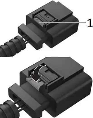
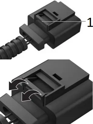
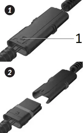
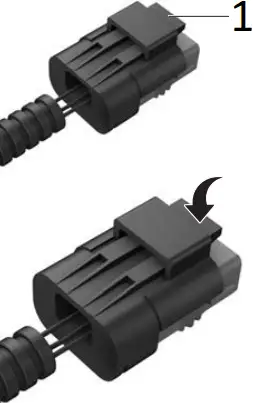
- Locking clip
In the first step, the red locking clip is pulled out. Press the red locking clip, which functions as a lever for loosening the plug and pulling it out.
Because the plug is often connected very tightly to the socket, it is helpful, when pressing the locking clip, to first push the plug towards the connection socket before subsequently pulling on it.
In addition, temperature fluctuations in the engine bay can result in a type of “vacuum effect” between the plug and the socket. This can be solved by lightly “wiggling” the plug.
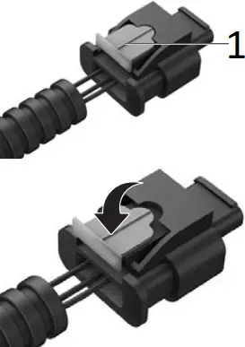
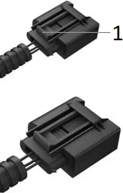
- Locking clip
The plugs are locked into the connection sockets by means of a locking clip. Press the locking clip and pull the plug.
Because the plug is often connected very tightly to the socket, it is helpful, when pressing the locking clip, to first push the plug towards the connection socket before subsequently pulling on it.
In addition, temperature fluctuations in the engine bay can result in a type of “vacuum effect” between the plug and the socket. This can be solved by lightly “wiggling” the plug.
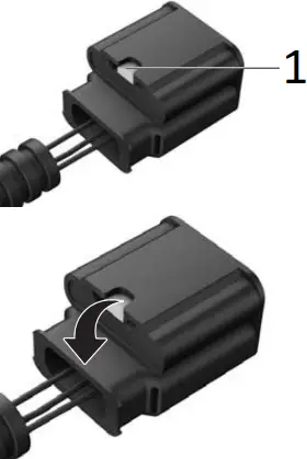
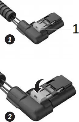
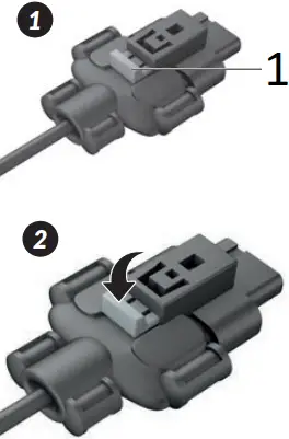
- Locking clip
The first step involves pulling out the bright grey locking clip. Press down on the bright grey locking clip, which serves as a switch for releasing and removing the plug.
Because the plug is often connected very tightly to the socket, it is helpful, when pressing the locking clip, to first push the plug towards the connection socket before subsequently pulling on in.
In addition, temperature fluctuations in the engine bay can result in a type of “vacuum effect” between the plug and the socket. This can be solved by lightly “wiggling” the plug.
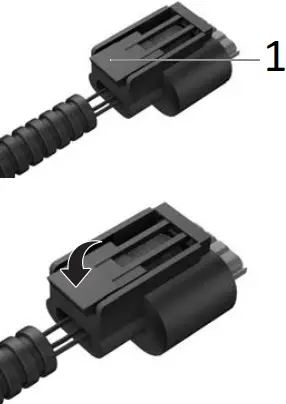
- Locking clip
The plugs are locked into the connection sockets by means of a locking clip. Press the locking clip and pull the plug.
Because the plug is often connected very tightly to the socket, it is helpful, when pressing the locking clip, to first push the plug towards the connection socket before subsequently pulling on it.
In addition, temperature fluctuations in the engine bay can result in a type of “vacuum effect” between the plug and the socket. This can be solved by lightly “wiggling” the plug.
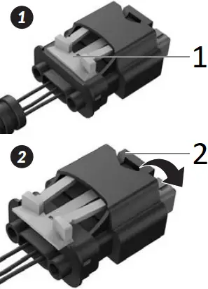
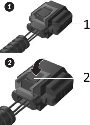
- Locking clip 1
- Locking clip 2
In the first step, the orange locking clip 1 is pulled out. Press the black locking clip 2, which functions as a lever for loosening the plug and pulling it out.
Because the plug is often connected very tightly to the socket, it is helpful, when pressing the locking clip, to first push the plug towards the connection socket before subsequently pulling on it.
In addition, temperature fluctuations in the engine bay can result in a type of “vacuum effect” between the plug and the socket. This can be solved by lightly “wiggling” the plug.
- Locking clip 1
- Locking clip 2
In the first step, the red locking clip 1 is pulled out. Press the black locking clip 2, which functions as a lever for loosening the plug and pulling it out.
Because the plug is often connected very tightly to the socket, it is helpful, when pressing the locking clip, to first push the plug towards the connection socket before subsequently pulling on it.
In addition, temperature fluctuations in the engine bay can result in a type of “vacuum effect” between the plug and the socket. This can be solved by lightly “wiggling” the plug.
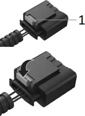
- Locking clip
In the first step, the grey locking clip is pulled out. Press the grey locking clip, which functions as a lever for loosening the plug and pulling it out.
Because the plug is often connected very tightly to the socket, it is helpful, when pressing the locking clip, to first push the plug towards the connection socket before subsequently pulling on it.
In addition, temperature fluctuations in the engine bay can result in a type of “vacuum effect” between the plug and the socket. This can be solved by lightly “wiggling” the plug.
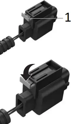
- Locking clip
In the first step, the grey locking clip is pulled out. Press the grey locking clip, which functions as a lever for loosening the plug and pulling it out.
Because the plug is often connected very tightly to the socket, it is helpful, when pressing the locking clip, to first push the plug towards the connection socket before subsequently pulling on it.
In addition, temperature fluctuations in the engine bay can result in a type of “vacuum effect” between the plug and the socket. This can be solved by lightly “wiggling” the plug.
- Locking clip
The plugs are locked into the connection sockets by means of a locking clip. Press the locking clip and pull the plug.
Because the plug is often connected very tightly to the socket, it is helpful, when pressing the locking clip, to first push the plug towards the connection socket before subsequently pulling on it.
In addition, temperature fluctuations in the engine bay can result in a type of “vacuum effect” between the plug and the socket. This can be solved by lightly “wiggling” the plug.
- Locking clip
The plugs are locked into the connection sockets by means of a locking clip. Pull slightly the locking clip and pull the plug.
Because the plug is often connected very tightly to the socket, it is helpful, when pressing the locking clip, to first push the plug towards the connection socket before subsequently pulling on it.
In addition, temperature fluctuations in the engine bay can result in a type of “vacuum effect” between the plug and the socket. This can be solved by lightly “wiggling” the plug.
- Locking clip
The plugs are locked into the connection sockets by means of a locking clip. Press the locking clip and pull the plug.
Because the plug is often connected very tightly to the socket, it is helpful, when pressing the locking clip, to first push the plug towards the connection socket before subsequently pulling on it.
In addition, temperature fluctuations in the engine bay can result in a type of “vacuum effect” between the plug and the socket. This can be solved by lightly “wiggling” the plug.
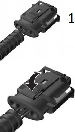
- Locking clip
In the first step, the orange locking clip is pulled out. Press the orange locking clip, which functions as a lever for loosening the plug and pulling it out.
Because the plug is often connected very tightly to the socket, it is helpful, when pressing the locking clip, to first push the plug towards the connection socket before subsequently pulling on it.
In addition, temperature fluctuations in the engine bay can result in a type of “vacuum effect” between the plug and the socket. This can be solved by lightly “wiggling” the plug.
- Locking clip
The plugs are locked into the connection sockets by means of a locking clip. Press the locking clip and pull the plug.
Because the plug is often connected very tightly to the socket, it is helpful, when pressing the locking clip, to first push the plug towards the connection socket before subsequently pulling on it.
In addition, temperature fluctuations in the engine bay can result in a type of “vacuum effect” between the plug and the socket. This can be solved by lightly “wiggling” the plug.
- Locking clip
The first step involves pulling out the bright gray locking clip. Press down on the bright grey locking clip, which serves as a switch for releasing and removing the plug.
Because the plug is often connected very tightly to the socket, it is helpful, when pressing the locking clip, to first push the plug towards the connection socket before subsequently pulling on in.
In addition, temperature fluctuations in the engine bay can result in a type of “vacuum effect” between the plug and the socket. This can be solved by lightly “wiggling” the plug.
Your plug is not listed? Please contact our Customer Service staff.


