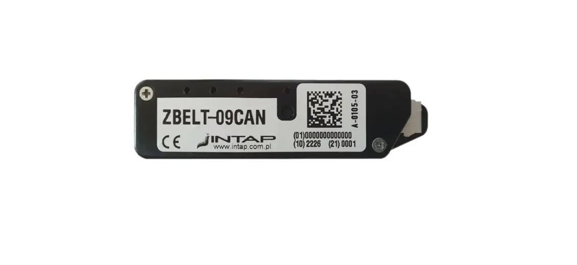
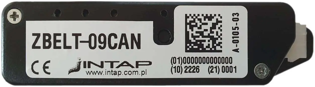
INTAP ZBELT-09CAN Base Module
General information
The ZBELT-09 system is designed to signal the lack of fastening of seat belts in special vehicles not equipped with such a system at the factory. A characteristic feature of the system is wireless communication between devices in the 868MHz band. The system contains two types of devices:
- BELT-09CAN basis module installed in vehicle
- ZBELT-0F seat module installed in the armchair.
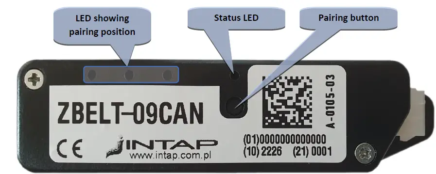
A maximum of 8 seats can be assigned to the driver module. The occupancy status of the seats as well as the fastening status of the seat belts is sent via the CAN bus. The device is equipped with a button used to pair the seat modules.
Base module – Installation in the vehicle
The driver module is installed in a place that provides the possibility of connecting the power supply and CAN BUS of the vehicle control system. Care should also be taken to ensure that this place provides the possibility of radio communication with the seat modules. It is unacceptable to place it in a place that shields electromagnetic waves, i.e. in a metal housing.
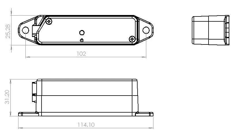
The module is fixed with two screws with a maximum diameter of 5mm.
Base module – Electrical connection
The device is equipped with a male 6-terminal MINI-FIT connector.
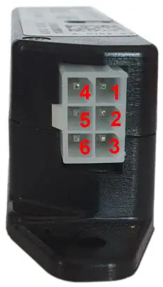
ZBELT-09CAN Signal outputs at the connector
| PIN | Function | Remarks |
| 1 | Ground | |
| 2 | +12V/+24V Power | Constant power supply through 0.5A fuse |
| 3 | Positive input | Optionally +15 signal |
| 4 | CAN – H | CAN High signal |
| 5 | CAN – L | CAN Low signal |
| 6 | Negative input | Optionally speed signal – ground active |
For proper operation of the base module, it is required to connect a constant power supply available after removing the ignition key, ground and CAN communication lines.
Base Module – Device Status
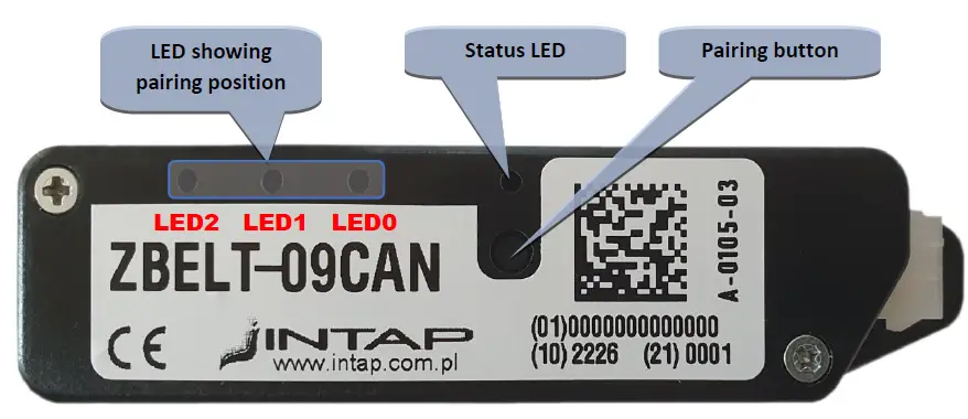
| Pairing LEDs | ||||||
| State | status LED | 2 | 1 | 0 | ||
| Normal operation | Short red flashes = presence of power Short green flash = received radio frame | Dark | ||||
| Pairing | Short red flashes = presence of power Short green flash = received radio frame | 1 | ON | |||
| 2 | ON | |||||
| 3 | ON | ON | ||||
| 4 | ON | |||||
| 5 | ON | ON | ||||
| 6 | ON | ON | ||||
| 7 | ON | ON | ON | |||
| 8 | ON | ON | ON | |||
| Lack of Pairing | Solid red | ON | ||||
| Module reset | Solid red | ON | ON | ON | ||
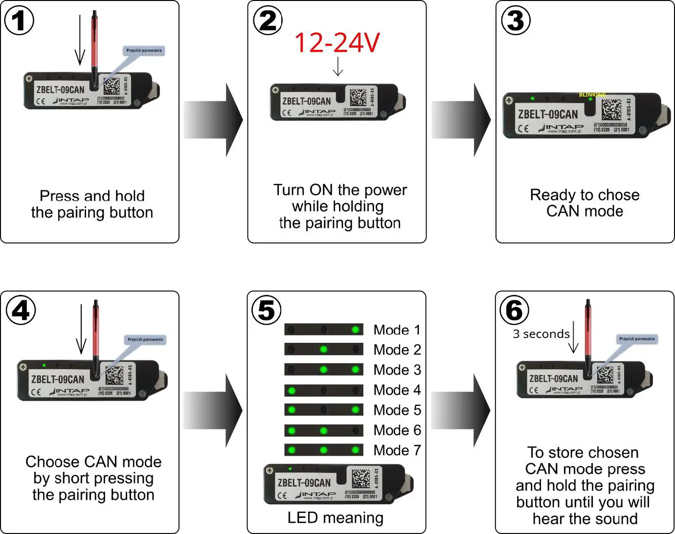
| CAN BUS Mode select | GREEN Fast blinking | Mode 1 | ON | |||
| Mode 2 | ON | |||||
| Mode 3 | ON | ON | ||||
| Mode 4 | ON | |||||
| Mode 5 | ON | ON | ||||
| Mode 6 | ON | ON | ||||
| Mode 7 | ON | ON | ON | |||
The module resets whenever the power is switched on, but it can also be caused by a problem with CAN communication (no frame confirmation) or a module hanging causing the Watchdog system to work.
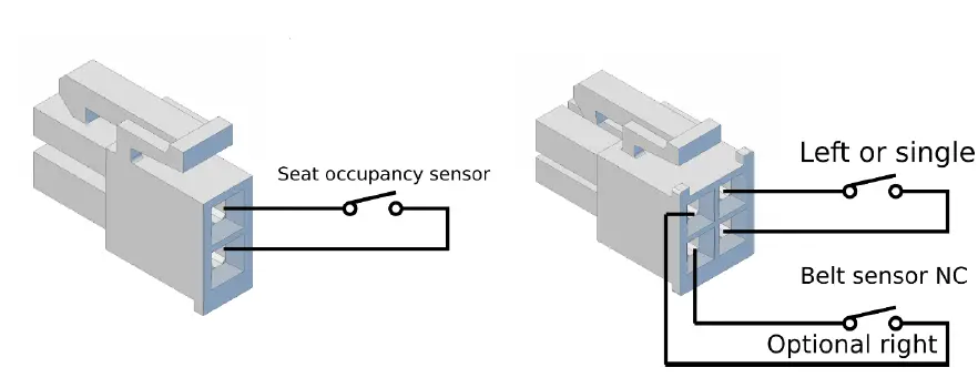
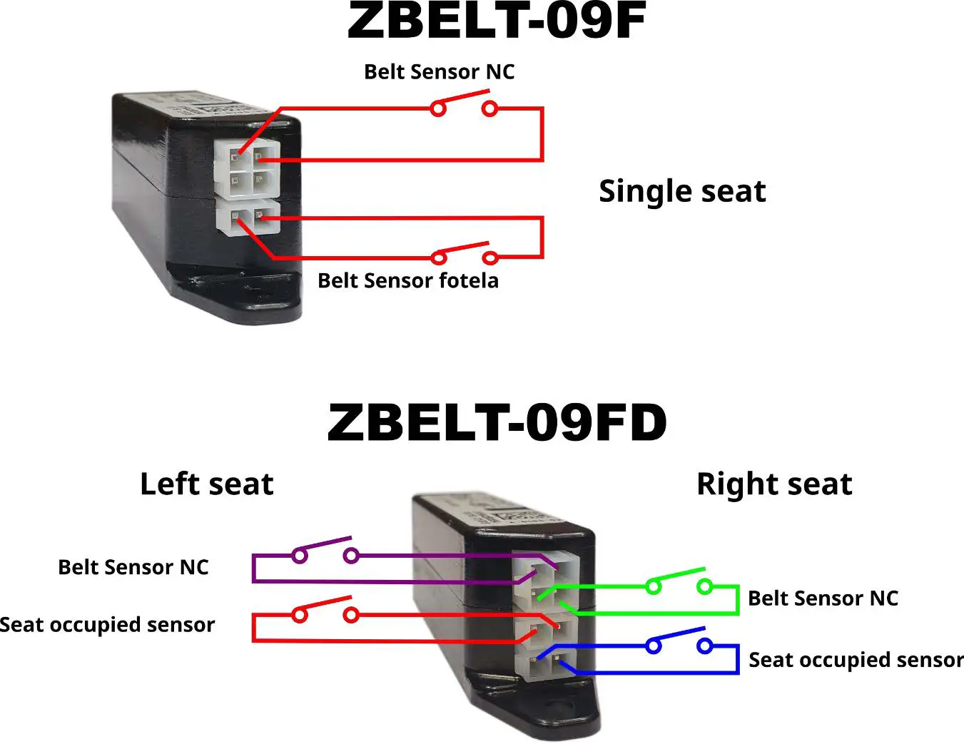
Seat module connections
There are two sensors connected to the seat module:
- Seat occupancy pressure sensor – closed when the seat is occupied
- Micro-switch located in the safety belt buckle – short when the belt is not fastened
Seats pairing process
In order for the system to work properly, it is required to assign the seats to their numbers in the system so that the display system can present them properly.
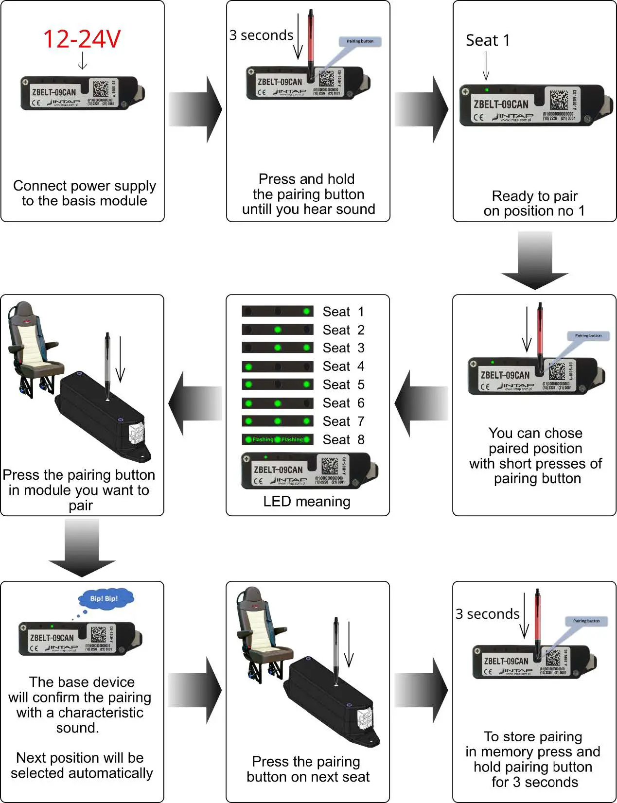
- If you pair an seat in a new location, the system will automatically free up its old position. Multiple pairing of the same chair in subsequent positions will result in their erasing one by one.
- Pairing the seat with another base module will erase the pairing with the current module. So the chair module can be paired with only one base.
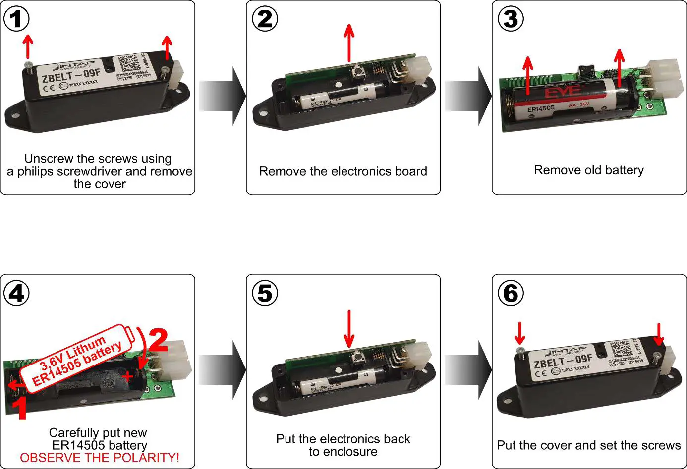
Replacing battery in the seat module
The seat module is powered by a 3,6V lithium battery placed inside the module. The battery should last at least two years. You need to replace it when the driver’s panel indicates low battery by flashing the seat belt symbol.
You should use ER14505 battery type.
Please note that it is NOT popular 1.5V AA battery. Using other battery will damage the module!
To replace battery you have to open seat module. Please follow instructions below.
Technical data
Seat module ZBELT-09F
- Rated supply voltage 3,6V – lithium battery ER14505
- Power consumption ~1.4uA in waking time mode
- Transmitter power ~8dBm ERP
- Radio frequency 868,5MHz
- Type of modulation LORA
- Battery life 4 years
Moduł bazowy ZBELT-09CAN
- Rated supply voltage 12V lub 24V
- Power consumption ~4mA@12V w czuwaniu
- Transmitter power ~11dBm ERP
- Radio frequency 868,5MHz
- Type of modulation LORA
The housings of the ZBELT-09CAN and ZBELT-09F modules are identical:
Installer settings – CAN Bus mode select
The ZBELT-09CAN device can cooperate with various control systems with which the bodybuilder equips the vehicles. In order for the communication to work properly, it is necessary to select the speed of the CAN bus, the type of identifier (11/29bit) and frame IDs. The ZBELT-09 device can operate in one of 7 modes.
| Setting | Bus speed | ID mode | FRAME IDENTIFIERS | ||
| number | SEAT_OCCUPATION | ZBELT_COMMAND | ZBELT_INFO | ||
| 1 | 250kbit | 11bit | 0x75 | 0x76 | 0x77 |
| 2 | 250kbit | 29bit | 0x18F0075 | 0x18F0076 | 0x18F0077 |
| 3 | 500kbit | 11bit | 0x75 | 0x76 | 0x77 |
| 4 | 500kbit | 29bit | 0x18F0075 | 0x18F0076 | 0x18F0077 |
| 5 | Do not use ! Reserved for future use. | ||||
| 6 | |||||
| 7 | |||||
CAN frames format
| Data | SEAT_OCCUPATION | Send Address / ID | SEAT_OCCUPATION_ID | ||||||||
| CYCLE | 1000ms | Speed | |||||||||
| Length | 5 bytes | Transmission direction | ZBELT-09CAN -> USER SYSTEM | ||||||||
| Decryption | Bit 7 | Bit 6 | Bit 5 | Bit 4 | Bit 3 | Bit 2 | Bit 1 | Bit 0 | |||
| Byte 0 | Green LED (seat occupied, belt fastened) | Seat8_green | Seat7_green | Seat6_green | Seat5_green | Seat4_green | Seat3_green | Seat2_green | Seat1_green | ||
| Byte 1 | Red LED (seat occupied, belt not fastened) | Seat8_red | Seat7_red | Seat6_red | Seat5_red | Seat4_red | Seat3_red | Seat2_red | Seat1_red | ||
| Byte 2 | Pairing Status (1=paired, 0=free) | Seat8_pair | Seat7_pair | Seat6_pair | Seat5_pair | Seat4_pair | Seat3_pair | Seat2_pair | Seat1_pair | ||
| Byte 3 | Low Battery warning | Seat8_LBW | Seat7_LBW | Seat6_LBW | Seat5_LBW | Seat4_LBW | Seat3_LBW | Seat2_LBW | Seat1_LBW | ||
| Byte 4 | Pairing in progress seat number | 8bit value – 0x0=not pairing, 0x01=waiting for seat 1 pairing, 0x02=waiting for seat 2 pairing……… | |||||||||
| UWAGI NOTES | |||||||||||
| Data | PAIRING | Send Address / ID | ZBELT_COMMAND_ID | |
| CYCLE | send once | Speed | ||
| Length | 1 bytes | Transmission direction | USER SYSTEM -> ZBELT-09CAN | |
| Byte 0 | Pairing order for seat no … | 8bit value – 0x00 = stop pairing, 0x01 = pair seat 1, 0x02 = pair seat 2, 0x03 = pair seat 3, …… 0x08 – pair seat 8 | ||
| UWAGI NOTES | After receiving the frame, the device waits for the chair module pairing in the position it received. After the module is paired, it returns to normal operation. Pairing the next seat requires another frame. | |||
| Data | PAIRING ERASE | Send Address / ID | ZBELT_COMMAND_ID | |
| CYCLE | send once | Speed | ||
| Length | 7 bytes | Transmission direction | USER SYSTEM -> ZBELT-09CAN | |
| Byte 0 | 0xFF | |||
| Byte 1 | 0x45 = ‘E’ | |||
| Byte 2 | 0x52= ‘R’ | |||
| Byte 3 | 0x41= ‘A’ | |||
| Byte 4 | 0x53= ‘S’ | |||
| Byte 5 | 0x45= ‘E’ | |||
| Byte 6 | 0x00 | |||
| UWAGI NOTES | To erase all paired seats, send the 0x76 frame containing 7 data bytes: 0xff “ERASE” 0x00 | |||
| Data | GET INFO | Send Address / ID | ZBELT_COMMAND_ID | |
| CYCLE | send once | Speed | ||
| Length | 1 bytes | Transmission direction | USER SYSTEM -> ZBELT-09CAN | |
| Byte 0 | 0xFE | |||
| UWAGI NOTES | Device will send one ZBELT_INFO frame. | |||
| Data | GIVE VERSION | Send Address / ID | ZBELT_INFO_ID | |||
| CYCLE | send once | Speed | ||||
| Length | 7 bytes | Transmission direction | ZBELT-09CAN -> USER SYSTEM | |||
| Byte 0 | CAN board firmware version | |||||
| Byte 1 | TRX PCB firmware version | |||||
| Byte 2 | TRX Frequency calibration factor | |||||
| Byte 3 | LSB | 0xF1 | 4 bytes serial numer i.e. 23030001 = 0x015F68F1 | |||
| Byte 4 | 0x68 | |||||
| Byte 5 | 0x5F | |||||
| Byte 6 | MSB | 0x01 | ||||
| UWAGI NOTES | This frame is for information purposes only. Implementation in user system is not necessary. | |||||


![Zkteco Elite Series [ti] Instruction Manual](https://static-data1.manualsee.com/1/img/320/5146398/2022/11/fb4f414223137c521cec43028c1d4580.jpg "Zkteco Elite Series [ti] Instruction Manual")


