PPI AIMS-4-8X Channel Analog to Modbus Converter
Product Information
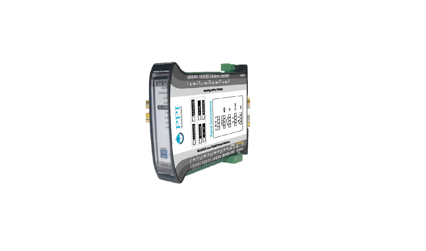
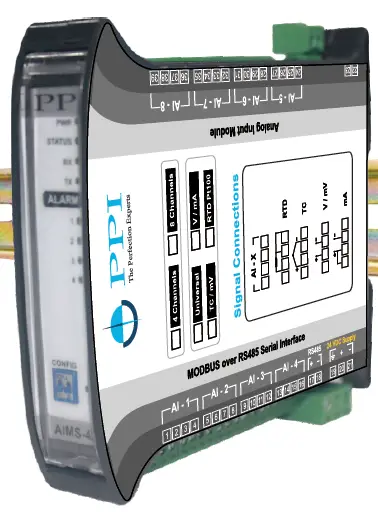
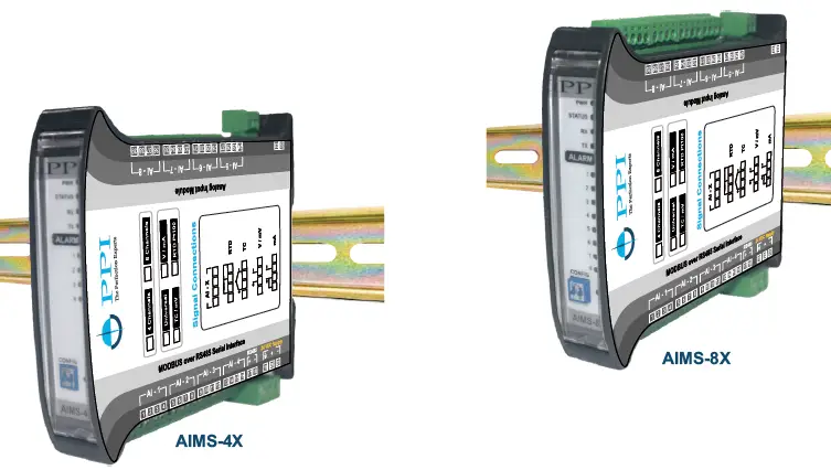
The AIMS-4/8X is a 4/8 channel DIN-rail analog input module with MODBUS over RS485 serial interface. It operates on a 20~32 VDC supply and has input type versions YU, YP, YT, and YD. Each channel is independently configurable for thermocouples, RTD Pt100, volts, mV, and mA. The AIMS-4X and AIMS-8X come with a user manual that contains information on electrical connections, parameters, mechanical dimensions, configuring communication parameter, DC linear signal interface, bottom/top clipping, and process value in ‘float’ data format.
Product Usage Instructions
Electrical Connections
- Observe the Local Electrical Regulations.
- Do not make any connections to the unused terminals for making a tie-point for other wires (or for any other reasons) as they may have some internal connections.
- Run power supply cables separated from the low-level signal cables (like RTD, Thermocouples, DC Linear Current / Voltage etc.). If the cables are run through conduits, use separate conduits for power supply cable and low-level signal cables.
- Use appropriate fuses and switches, wherever necessary, for driving the high voltage loads to protect the module from any possible damage due to high voltage surges of extended duration or short-circuits on loads.
- Take care not to over-tighten the terminal screws while making connections.
- Make sure that the module supply is switched-off while making/removing any connections.
Input Channels
Each of the 4 or 8 input channels are identical from wiring connection viewpoint. For explanation purpose, the 4 terminals pertaining to each channel have been marked as T1, T2 ,T3 & T4 in the following pages. The descriptions below apply to all the channels with no deviations.
Thermocouple
Connect Thermocouple Positive (+) to terminal T2 and Negative
(-) to terminal T3 as shown in Figure 1.2. Use the correct type of
Thermocouple extension lead wires or compensating cable for the
entire distance ensuring the correct polarity throughout. Avoid
joints in the cable.
RTD Pt100, 3-wire
Connect single leaded end of RTD bulb to terminal T2 and the double leaded ends to terminals T3 and T4 (interchangeable) as shown in Figure 1.3. Use copper conductor leads of very low resistance ensuring that all 3 leads are of the same gauge and length. Avoid joints in the cable.
DC Linear Voltage (mV / V)
Use a shielded twisted pair with the shield grounded at the signal source for connecting mV / V source. Connect common (-) to terminal T3 and the signal (+) to terminal T2, as shown in Figure 1.4.
MODELS
Input Type Versions
- U: Each Channel is Independently Configurable for Thermocouples, RTD Pt100, Volts, mV and mA (No Jumper Settings)
- P: All Channels RTD Pt100 (3-Wire)
- T: All Channels Thermocouples / mV
- D: All Channels DC V/mA
ELECTRICAL CONNECTIONS
WARNING: MISHANDLING / NEGLIGENCE CAN RESULT IN PERSONAL DEATH OR SERIOUS INJURY.
- The user must rigidly observe the Local Electrical Regulations.
- Do not make any connections to the unused terminals for making a tie-point for other wires (or for any other reasons) as they may have some internal connections. Failing to observe this may result in permanent damage to the indicator.
- Run power supply cables separated from the low-level signal cables (like RTD, Thermocouples, DC Linear Current / Voltage etc.). If the cables are run through conduits, use separate conduits for power supply cable and low-level signal cables.
- Use appropriate fuses and switches, wherever necessary, for driving the high voltage loads to protect the module from any possible damage due to high voltage surges of extended duration or short-circuits on loads.
- Take care not to over-tighten the terminal screws while making connections.
- Make sure that the module supply is switched-off while making/removing any connections.
CONNECTION DIAGRAM
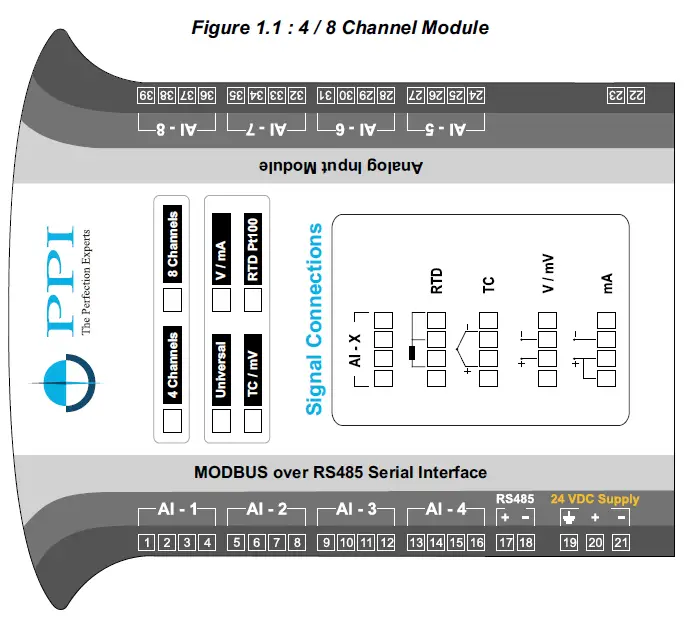
- The Figure 1.1 illustrates Electrical Connection Diagrams. For 4 Channel Version the connectors for AI-5 to AI-8 are not fitted.
INPUT CHANNELS
Each of the 4 or 8 input channels are identical from wiring connection viewpoint. For explanation purpose, the 4 terminals pertaining to each channel have been marked as T1, T2 ,T3 & T4 in the following pages. The descriptions below apply to all the channels with no deviations.
Thermocouple
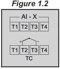
Connect Thermocouple Positive (+) to terminal T2 and Negative (-) to terminal T3 as shown in Figure 1.2. Use the correct type of Thermocouple extension lead wires or compensating cable for the entire distance ensuring the correct polarity throughout. Avoid joints in the cable.
RTD Pt100, 3-wire
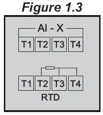
Connect single leaded end of RTD bulb to terminal T2 and the double leaded ends to terminals T3 and T4 (interchangeable) as shown in Figure 1.3. Use copper conductor leads of very low resistance ensuring that all 3 leads are of the same gauge and length. Avoid joints in the cable.
DC Linear Voltage (mV / V)
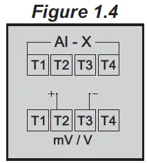
Use a shielded twisted pair with the shield grounded at the signal source for connecting mV / V source. Connect common (-) to terminal T3 and the signal (+) to terminal T2, as shown in Figure 1.4.
DC Linear Current (mA)
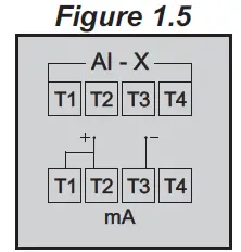
Use a shielded twisted pair with the shield grounded at the signal source for connecting mA source. Connect common (-) to terminal T3 and the signal (+) to terminal T2. Also short terminals T1 & T2. Refer Figure 1.5.
POWER SUPPLY (Terminals 20, 21)
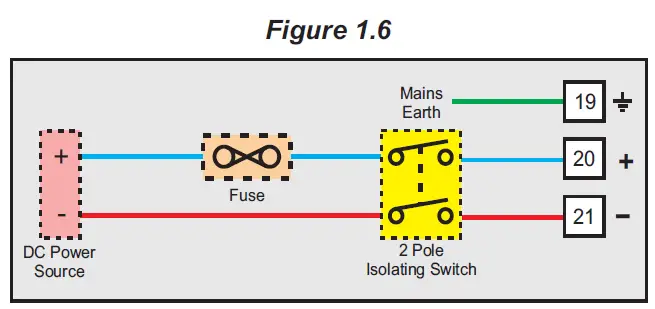
As standard, the Module is supplied with power connections suited for 20 to 32 VDC power source. The accuracy / performance of the Module is not affected by the variations in the supply within specified limits of 20 to 32 VDC. Use wellinsulated copper conductor wire of the size not smaller than 0.5mm² for power supply connections ensuring proper polarity as shown in Figure 1.6. The Module is not provided with fuse and power switch. If necessary, mount them separately. Use a slow blow fuse rated for 0.5A current.
For safety and enhanced electrical noise immunity, it is highly recommended to connect Main Power Supply ‘Earth’ to terminal 19.
SERIAL COMMUNICATION POR
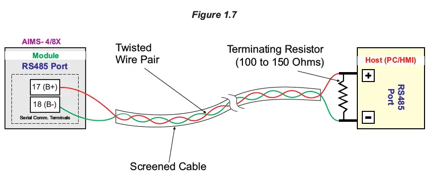
The wiring connections for interfacing the Host (PC/HMI) with AIMS is shown in the figure 1.7. For reliable noise free communication, use a pair of twisted wires inside screened cable. The wire should have less than 100 ohms / km nominal DC resistance (Typically 24 AWG or thicker). Connect the terminating resistor (Typically 100 to 150 ohm) at one end to improve noise immunity.
Note
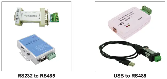
In case of non-availability of RS485 port on Host PC, use appropriate Serial Protocol Converter to match the available serial port on the host like USB to RS485 and RS232 to RS485 (Refer few images below). Please ensure that the appropriate Device Driver for the selected converter is installed on the Host PC.
PARAMETERS
- The Module supports industry standard MODBUS RTU over Serial Protocol for communicating Process Values, Alarm Status & Operation Parameters for various Channels.
- The communication parameter settings and the data packet format have been discussed in Section 4 : Configuring Communication Parameters.
- To minimize the protocol complexity at Master end, all the parameters have been assembled as Registers. The Read Only parameters are specified as Input Registers while the Read/Write parameters are specified as Holding Registers.
- The Table 2.1 describes Input Registers (Read only parameters) and Table 2.2 describes Holding Registers (Read/Write Parameters), respectively. The MODBUS addresses are also specified.
Table 2.1: Input Registers (Read-Only Parameters)
| Parameter Description | MODBUS Address | Values | ||||||||
| Process Value (Note1) Measured Temperature (in °C / °F) for Thermocouple / RTD inputs or Scaled Counts for DC Volts / mA inputs. Note : The Process Values are also available in 32- Bit Single Precision Float format. Refer Appendix-C. | 1561 to 1564 (4 Channels)
1561 to 1568 (8 Channels) | Signed integer values from -30000 to +30000 representing the measured process values. Refer Table 2.3 for the various input types and the corresponding measured ranges. The following constant counts indicate PV Errors.
| ||||||||
| Alarm-1 Status | 1577 | 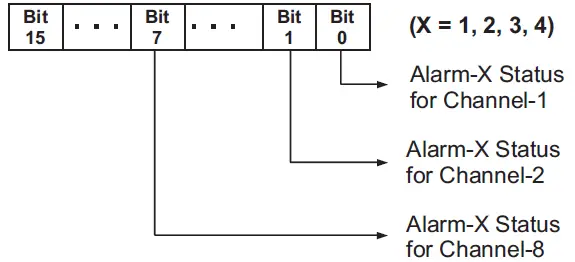
For 4 Channel Version (AIMS-4X), ignore Bit-4 to Bit-15 For 8 Channel Version (AIMS-8X), ignore Bit-8 to Bit-15 | ||||||||
| Alarm-2 Status | 1578 | |||||||||
| Alarm-3 Status | 1579 | |||||||||
| Alarm-4 Status | 1580 | |||||||||
| Ambient Temperature (Applicable only for Versions supporting Thermocouple Inputs)
Room Temperature (in °C) measured by the sensor mounted inside the instrument. | 82 | Signed integer values from -30000 to +30000 representing the measured Ambient Temperature through the semi- conductor sensor mounted on the Module. The measured value is always in °C with 0.1 resolution. For example, 30.0°C is represented as 300. |
Table 2.2: Holding Registers (Read/Write Parameters)
| Parameter Description | MODBUS Address | Settings (Default Value) | ||||||||||||||||||||||||||||||||||||||||||||||||||||||||||||
| Input Type Select Input type in accordance with the type of Thermocouple or RTD sensor or transducer output connected for process value measurement. | 83 to 86 (4 Channels)
83 to 90 (8 Channels) | Applicable for Input Type TC / RTD Pt100 / V / mV / mA
(Default: 0 to 10 V) Applicable for Input Type RTD Pt100
Applicable for Input Type TC / mV
(Default : Type K) |
Applicable for Input Type V / mA
(Default : 0 to 10 V) | ||||||||||||||||
| Temperature Units (Applicable only for Versions supporting Thermocouples & RTD Pt100 Inputs)
Selects temperature measurement units in °C or °F. | 99 to 102 (4 Channels)
99 to 106 (8 Channels) | Conditional Parameter (Note2)
(Default : °C) | ||||||||||||||
| DC Resolution (Note1) (Applicable only for Versions supporting mV / V / mA Inputs)
This parameter value should be used in conjunction with the process value for interpretation of decimal place. For example if the value for this parameter is 0.01 then the measured process value of 3000 should be interpreted as 30.00. | 115 to 118 (4 Channels)
115 to 122 (8 Channels) | Conditional Parameter (Note2)
(Default : 1 Unit for DC Linear input & 0.1 for Thermocouple & RTD) |
| Signal Low (Applicable only for Versions supporting mV / V / mA Inputs) The transmitter output signal value corresponding to Range Low process value. Refer Appendix-A : DC Linear Signal Interface for details. Note : The value should be set as integer counts ignoring decimal value. For e.g. 4.00 mA should be set as 400 counts. | 501 to 504 (4 Channels)
501 to 508 (8 Channels) | Conditional Parameter (Note2)
| ||||||||||||||||||||||||
| Signal High (Applicable only for Versions supporting mV / V / mA Inputs) The transmitter output signal value corresponding to Range High process value. Refer Appendix-A : DC Linear Signal Interface for details. Note : The value should be set as integer counts ignoring decimal value. For e.g. 80.00 mV should be set as 8000 counts. | 517 to 520 (4 Channels)
517 to 524 (8 Channels) | Conditional Parameter (Note2)
| ||||||||||||||||||||||||
| Range Low (Applicable only for Versions supporting mV / V / mA Inputs) The process value corresponding to the Signal Low value from the transmitter. Refer Appendix-A : DC Linear Signal Interface for details. | 131 to 134 (4 Channels)
131 to 138 (8 Channels) | Conditional Parameter (Note2)
-30000 to 30000 (Default : 0) | ||||||||||||||||||||||||
| Range High (Applicable only for Versions supporting mV / V / mA Inputs) The process value corresponding to the Signal High value from the transmitter. Refer Appendix-A : DC Linear Signal Interface for details. | 147 to 150 (4 Channels) 147 to 154 (8 Channels) | Conditional Parameter (Note2)
-30000 to 30000 (Default : 1000) | ||||||||||||||||||||||||
| Offset for PV (Note1) This value is algebraically added to the measured PV to derive the final PV. Final PV = Measured PV + Offset | 163 to 166 (4 Channels)
163 to 170 (8 Channels) | -30000 to 30000 (Default : 0) |
| Parameter Description | MODBUS Address | Settings (Default Value) | ||||||||
| Alarm-1 Type Refer Alarm-4 Type | 179 to 182 (4 Channels) 179 to 186 (8 Channels) |
(Default: None) | ||||||||
| Alarm-2 Type Refer Alarm-4 Type | 243 to 246 (4 Channels) 243 to 250 (8 Channels) | |||||||||
| Alarm-3 Type Refer Alarm-4 Type | 307 to 310 (4 Channels) 307 to 314 (8 Channels) | |||||||||
| Alarm-4 Type None The Alarm function is disabled. Process Low The Alarm is activated upon the PV equaling or falling below the ‘Alarm Set-point’ value. Process High The Alarm is activated upon the PV equaling or rising above the ‘Alarm Set-point’ value. | 371 to 374 (4 Channels) 371 to 378 (8 Channels) | |||||||||
| Alarm-1 Set-point (Note1) Refer Alarm-4 Set-point | 195 to 198 (4 Channels) 195 to 202 (8 Channels) |
Min. to Max. Range specified for the selected Input Type Refer Table 2.3 (Default : Min or Max Range depending on the Alarm type) | ||||||||
| Alarm-2 Set-point (Note1) Refer Alarm-4 Set-point | 259 to 262 (4 Channels) 259 to 266 (8 Channels) | |||||||||
| Alarm-3 Set-point (Note1) Refer Alarm-4 Set-point | 323 to 326 (4 Channels) 323 to 330 (8 Channels) | |||||||||
| Alarm-4 Set-point (Note1) Sets limit for Process-High or Process-Low Alarm. | 387 to 390 (4 Channels) 387 to 394 (8 Channels) |
| Parameter Description | MODBUS Address | Settings (Default Value) | ||||||
| Alarm-1 Hysteresis (Note1) Refer Alarm-4 Hysteresis | 211 to 214 (4 Channels) 211 to 218 (8 Channels) |
1 to 30000 (Default : 20) | ||||||
| Alarm-2 Hysteresis (Note1) Refer Alarm-4 Hysteresis | 275 to 278 (4 Channels) 275 to 282 (8 Channels) | |||||||
| Alarm-3 Hysteresis (Note1) Refer Alarm-4 Hysteresis | 339 to 342 (4 Channels) 339 to 346 (8 Channels) | |||||||
| Alarm-4 Hysteresis (Note1) Sets differential (dead) band between Alarm switching ON and OFF states. | 403 to 406 (4 Channels) 403 to 410 (8 Channels) | |||||||
| Alarm-1 Inhibit Refer Alarm-4 Inhibit | 227 to 230 (4 Channels) 227 to 234 (8 Channels) |
(Default: Disable) | ||||||
| Alarm-2 Inhibit Refer Alarm-4 Inhibit | 291 to 294 (4 Channels) 291 to 298 (8 Channels) | |||||||
| Alarm-3 Inhibit Refer Alarm-4 Inhibit | 355 to 358 (4 Channels) 355 to 362 (8 Channels) | |||||||
| Alarm-4 Inhibit Enable The Alarm activation is suppressed until the PV is within Alarm limits from the time the Module is Powered- on. This allows suppressing the Alarm during the start-up Alarm conditions. Disable The Alarm is not suppressed during the start- up Alarm conditions. | 419 to 422 (4 Channels) 419 to 426 (8 Channels) |
| Enable Bottom Clipping (Applicable only for Versions supporting mV / V / mA Inputs) Refer Appendix-B. | 435 to 438 (4 Channels) 435 to 442 (8 Channels) |
(Default: No) | ||||||
| Bottom Clip Value (Applicable only for Versions supporting mV / V / mA Inputs) Refer Appendix-B. | 451 to 454 (4 Channels) 451 to 458 (8 Channels) |
-30000 to 30000 (Default : 0) | ||||||
| Enable Top Clipping (Applicable only for Versions supporting mV / V / mA Inputs) Refer Appendix-B. | 467 to 470 (4 Channels) 467 to 474 (8 Channels) |
(Default : No) | ||||||
| Top Clip Value (Applicable only for Versions supporting mV / V / mA Inputs) Refer Appendix-B. | 483 to 486 (4 Channels) 483 to 490 (8 Channels) | -30000 to 30000 (Default : 1000) |
Note 1
Thermocouples (J, K, T, R, S, B, N) and RTD Pt100 (3-wire) Inputs
The process value is always measured in 0.1°C/°F resolution. That is, for example, the value 300 means 30.0°C / °F. The same should be followed while setting the values for the parameters that are resolution based (like Zero Offset, Alarm Set-point, Alarm Hysteresis, etc.). That is for example, set 300 counts for 30.0°C / °F.
DC mA/mV/V Inputs
(Also Refer Appendix A : DC Linear Signal Interface)
The measured PV is a Resolution-less Scaled Value derived using the values for the parameters : Signal Low, Signal High, Range Low and Range High. The parameter ‘DC Resolution’ holds the desired resolution that can be used to insert appropriate Decimal Place in the scaled PV. For example, if the DC Resolution value is 2 (0.01) then the scaled value of 3000 can be read as 30.00. Similarly the corresponding parameters like Zero Offset, Alarm Set-point, Alarm Hysteresis, etc., are also resolution less and, if desired, the parameter value for ‘DC Resolution’ should be used for appropriate Decimal Place.
Note 2: Conditional Parameters are those whose usage depend upon the values set for some other parameters. For example; the parameters ‘Signal Low’ & ‘Signal High’ for a selected channel are used only if the input type for the selected channel is DC Input (mV / V / mA). The access to the conditional parameters for Read / Write operation, however, is not restricted.
| Input Type | Range (Min. to Max.) | Resolution | |
| Type J Thermocouple | 0 to +960.0°C / +32.0 to +1760.0°F |
0.1 °C / °F | |
| Type K Thermocouple | -200.0 to +1376.0°C / -328.0 to +2508.0°F | ||
| Type T Thermocouple | -200.0 to +387.0°C / -328.0 to +728.0°F | ||
| Type R Thermocouple | 0 to +1771.0°C / +32.0 to +3219.0°F | ||
| Type S Thermocouple | 0 to +1768.0°C / +32.0 to +3214.0°F | ||
| Type B Thermocouple | 0 to +1826.0°C / +32.0 to +3218.0°F | ||
| Type N Thermocouple | 0 to +1314.0°C / +32.0 to +2397.0°F | ||
| 3-wire, RTD Pt100 | -199.0 to +600.0°C / -328.0 to +1112.0°F | ||
| 0 to 20mA DC current | |||
| 4 to 20mA DC current | 1 | ||
| 0 to 80mV DC voltage | 0.1 | ||
| -30000 to 30000 units | 0.01 0.001 | ||
| 0 to 1.25V DC voltage | |||
| 0 to 5.0V DC voltage | |||
| 0.0001 | |||
| 0 to 10.0V DC voltage | Units | ||
| 1 to 5.0V DC voltage |
MECHANICAL DIMENSIONS
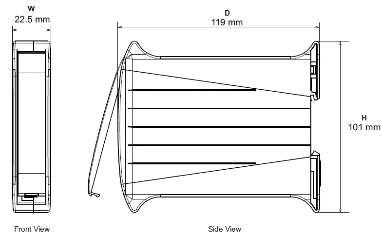
| Width (W) | 22.5 mm |
| Height (H) | 101.0 mm |
| Depth (D) | 119.0 mm |
CONFIGURING COMMUNICATION PARAMETERS
The Module (Analog Interface Module) supports industry standard MODBUS RTU over Serial Protocol for communicating Process Values, Alarm Status & Operation Parameters for various Channels. The Serial Communication Port specification are shown in Table 4.1 below.
| Port | RS485, 2-wire, Half duplex, Start-stop synchronized | |
| Protocol | Modbus RTU | |
|
Communication Parameters | Parameter | Settings |
| Slave ID | 1 to 247 | |
| Baud Rate | 2400, 4800, 9600, 19200, 38400, 57600, 115200 bps | |
| Parity | None (1 or 2 Stop Bits) Even (1 Stop Bit) odd (1 Stop Bit) | |
| Max. No. of Units per Loop | 31 | |
| Maximum Distance | 1200 Meters | |
The Module is shipped from the factory with the following default values for the Communication Parameters.
| Slave ID : 1 | Baud Rate : 9600 bps | Parity : Even |
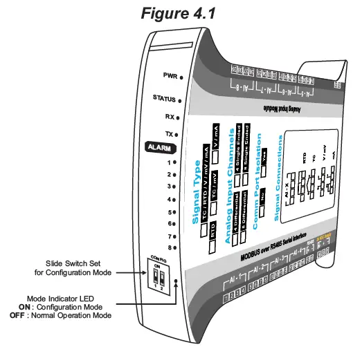
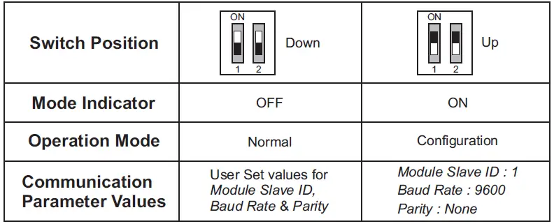
The above parameters can be altered to match with the Host (Master) parameters by putting the Module in Configuration Mode. In Configuration Mode, the Module always communicates with the host with the fixed communication parameter values (Slave ID : 1, Baud Rate : 9600 & Parity : None) regardless of the actual set values. The user set values are applicable only when the Module is put back in Normal Operation Mode. A Slide Switch Set is provided on the Module, as shown in the Figure 4.1, to select between the Configuration and Normal Operation modes. The Table 4.2 shows the Switch Positions and the respective mode.
It is important to note that the switch position is detected only upon power-up. Select the desired Mode while the Module is OFF. That is changing the switch position while the Module is powered does not have any effect on the Mode.
The Communication Parameters values can be altered by using the MODBUS RTU protocol while the Module is in Configuration Mode. Set the host (Master) Baud Rate to “9600 bps” and Parity to “None”. The MODBUS Addresses and Settings for the Module communication parameters are listed in the Table 4.3 below.
| Parameter Description | MODBUS Address | Settings (Default Value) | ||||||||||||||||
| Module Slave ID Unique numeric value assigned to the indicator for identification by the host. Set the value as required by the host. | 1 |
1 to 247 (Default : 1) | ||||||||||||||||
| Baud Rate Communication speed in ‘Bits per Second’. Set the value to match with the host baud rate. | 2 |
(Default : 9600 bps) | ||||||||||||||||
| Parity One of the communication error trapping features. Set the data packet parity as implemented by the host protocol. | 3 |
(Default : Even) |
APPENDIX A
APPENDIX A
DC LINEAR SIGNAL INTERFACE
This appendix describes the parameters required to interface process transmitters that produce Linear DC Voltage (mV/V) or Current (mA) signals in proportion to the measured process values. A few examples of such transmitters are;
- Pressure Transmitter producing 4 to 20 mA for 0 to 5 psi
- Relative Humidity Transmitter producing 1 to 4.5 V for 5 to 95 %RH
- Temperature Transmitter producing 0 to 20 mA for -50 to 250 °C
The instrument (indicator / controller / recorder) that accepts the linear signal from the transmitter computes the measured process value by solving the mathematical equation for Straight-Line in the form:
Y = mX + C
Where;
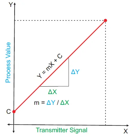
- X: Signal Value from Transmitter
- Y: Process Value Corresponding to Signal Value X
- C: Process Value Corresponding to X = 0 (Y-intercept)
- m: Change in Process Value per unit Change in Signal Value (Slope)
As is evident from the aforementioned transmitter examples, different transmitters produce signals varying both in type (mV/V/mA) and range. Most PPI instruments, thus, provide programmable Signal Type and Range to facilitate interface with a variety of transmitters. A few industry standard signal types and ranges offered by the PPI instruments are: ± 80mV, ± 5 V, ± 1 to ± 5 V, ± 10V, 0-20 mA, 4-20 mA, etc. Also, the output signal range (e.g. 1 to 4.5 V) from different transmitters corresponds to different process value range (e.g. 5 to 95 %RH); the instruments thus also provide facility for programming the measured process value range with programmable Resolution.
The linear transmitters usually specify two signal values (Signal Low and Signal High) and the corresponding Process Values (Range Low and Range High). In the example Pressure Transmitter above; the Signal Low, Signal High, Range Low & Range High values specified are: 4 mA, 20 mA, 0 psi & 5 psi, respectively.
In summary, the following 6 parameters are required for interfacing Linear Transmitters:
- Input Type: Standard DC Signal Type in which the transmitter signal range fits (e.g. 4-20 mA)
- Signal Low: Signal value corresponding to Range Low process value (e.g. 4.00 mA)
- Signal High: Signal value corresponding to Range High process value (e.g. 20.00 mA)
- PV Resolution: Resolution (least count) with which to compute process value (e.g. 0.01)
- Range Low: Process value corresponding to Signal Low value (e.g. 0.00 psi)
- Range High: Process value corresponding to Signal High value (e.g. 5.00 psi)
The following examples illustrate appropriate parameter value selections.
Example 1: Pressure Transmitter producing 4 to 20 mA for 0 to 5 psi
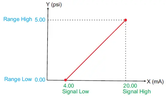
Presume the pressure is to be measured with 0.01 Resolution, that is 0.00 to 5.00 psi.
- Input Type: 4-20 mA
- Signal Low: 4.00 mA
- Signal High: 20.00 mA
- PV Resolution: 0.01
- Range Low: 0.00
- Range High: 5.00
Example 2: Relative Humidity Transmitter producing 1 to 4.5 V for 5 to 95 %RH
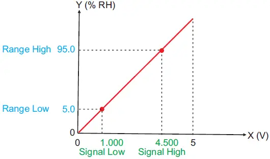
Presume the humidity is to be measured with 0.1 Resolution, that is 0.0 to 100.0 %.
- Input Type: 0-5 V
- Signal Low: 1.000 V
- Signal High: 4.500 V
- PV Resolution: 0.1
- Range Low: 5.0
- Range High: 95.0
Example 3: Temperature Transmitter producing 0 to 20 mA for -50 to 250 °C
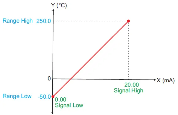
Presume the Temperature is to be measured with 0.1 Resolution, that is -50.0 to 250.0°C.
- Input Type: 0-20 mA
- Signal Low: 0.00 mA
- Signal High: 20.00 mA
- PV Resolution: 0.1
- Range Low: -50.0
- Range High: 250.0
APPENDIX B
BOTTOM / TOP CLIPPING
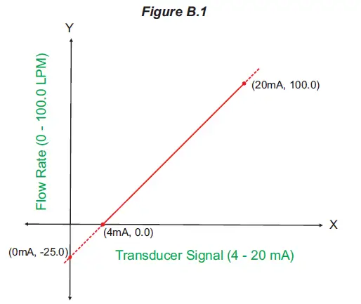
For mA/mV/V inputs the measured PV is a scaled value between the set values for ‘PV Range Low’ and ‘PV Range High’ parameters corresponding to the Signal Minimum and Signal Maximum values respectively. Refer Appendix A. The Figure B.1 below illustrates an example of flow rate measurement using a transmitter / transducer producing a signal range of 4 – 20 mA corresponding to 0.0 to 100.0 Liters per Minute (LPM).
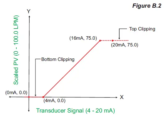
If this transmitter is to be used for a system having a flow rate range of 0.0 to 75.0 LPM then the actual useful signal range from the example transmitter is 4 mA (~ 0.0 LPM) to 16 mA (~ 75.0 LPM) only. If no Clipping is applied on the measured flow rate then the scaled PV will also include ‘out-of-range’ values for the signal values below 4 mA and above 16 mA (may be due to open sensor condition or calibration errors). These out-of-range values can be suppressed by enabling the Bottom and/or Top Clippings with appropriate Clip values as shown in figure B.2 below.
Parameter Values
- PV Range Low: 0.0
- PV Range High: 100.0
- Enable Bottom Clipping: Yes
- Bottom Clip Value: 0.0
- Enable Top Clipping: Yes
- Top Clip Value: 75.0
APPENDIX C
PROCESS VALUE IN ‘FLOAT’ DATA FORMAT
The measured Process Values for all channels can be read in 32-Bit Single Precision Float format at Modbus Addresses listed in the following table.
Read-Only Parameter
| Parameter Description | MODBUS Address | Values | ||||||||
| Process Value Measured Temperature (in °C / °F) for Thermocouple / RTD inputs or Scaled Counts for DC Volts / mA inputs. | 2001 to 2008 (4 Channels)
2001 to 2016 (8 Channels) | Single Precision Float values from -30000 to +30000 representing the measured process values. Refer Table 2.3 (Section 2) for the various input types and the corresponding measured ranges. The following constant counts indicate PV Errors.
|
The Process Values can be read in IEEE single precision floating point format in two adjacent 16-bit Modbus registers, the high order register first. The high-order register always starts at an odd Modbus address. For example, the process value for channel-1 is read in addresses 2001 (high-order register) & 2002 (low-order register). Within the register, the high-order byte is sent first in accordance to standard Modbus RTU format. The following example illustrates the register & byte sequence.
Process Value for Channel-1

The data is transferred in the following Byte-Sequence
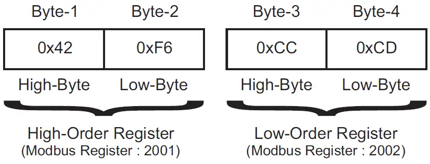
The Process Values for Thermocouple & RTD Pt100 Inputs is always transferred with 0.1 count resolution. The resolution for Process Values for DC Linear inputs is dependent on the value set for the Parameter DC Resolution (Modbus Addresses : 115 to 118 for 4 Channels & 115 to 122 for 8 Channels). For example, if the dc resolution parameter value is 2 & if the measured scaled integer counts are 12345 then the communicated process value is 123.45.
CONTACT
Process Precision Instruments
- 101, Diamond Industrial Estate, Navghar, Vasai Road (E), Dist. Palghar – 401 210.Maharashtra, India
- Sales: 8208199048 / 8208141446
- Support: 07498799226 / 08767395333
- [email protected],
- [email protected]
- www.ppiindia.net


