![]() DAUNIN CO.,LTD.
DAUNIN CO.,LTD.
2302EN
V2.0.0![]() and SIEMENS PLC
and SIEMENS PLC
Modbus RTU Connection
Operating Manual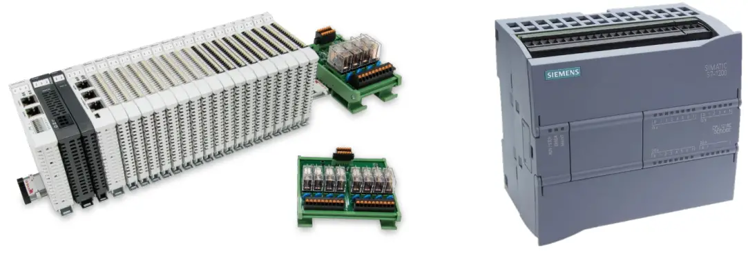
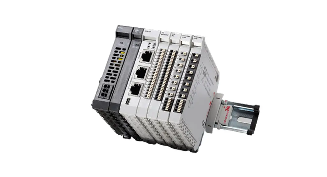
Remote I/O Module System Configuration List
| GFMS-RM01S | Master Modbus RTU, 1 Port | Main Controller |
| GFDI-RM01N | Digital Input 16 Channel | Digital Input |
| GFDO-RM01N | Digital Output 16 Channel / 0.5A | Digital Output |
| GFPS-0202 | Power 24V / 48W | Power Supply |
| GFPS-0303 | Power 5V / 20W | Power Supply |
| 0170-0101 | 8 pin RJ45 female connector/RS-485 Interface | Interface Module |
1.1 Product Description
- The interface module is used externally to convert Siemens CM 1241’s communication module (Modbus RTU) to a RJ45 connector
- The main controller is in charge of the management and dynamic configuration of I/O parameters and so on.
- The power module and interface module are standard for remote I/Os and users can choose the model or brand they prefer.
Siemens S7-1200 Connection Setup
This chapter explains how to use the TIA Portal program to connect S7-1200 to ![]() . For detailed information, please refer to the “SIMATIC STEP 7” section in the user’s manual
. For detailed information, please refer to the “SIMATIC STEP 7” section in the user’s manual
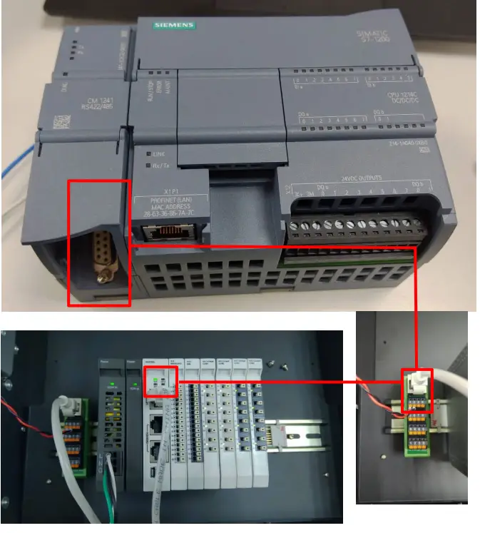
2.1 Siemens S7-1200 hardware connection
- The connector is at the bottom of the CM 1241 module and uses RS485 connections
Pin Description Connector Pin Description 1 Logic ground or communication ground 
6 PWR 2 TxD+ For RS422 connection and does not apply to RS485 7 Not connected 3 TxD+ Signal B (RxD/TxD+) 8 TxD- Signal A (RxD/TxD-) 4 RTS Request to send (TTLlevel signal) output 9 TxD- For RS422 connection and does not apply to RS485 5 GND Logic ground or communication ground SHELL Shell grounding Notes:
RS485 connection: Pin No.3—RS485 (Signal B) (+); Pin No.8—RS485 (Signal A) (-) No.1 pin’s isoelectric point - Connect the COM (RS485 A/B) at the bottom of CM1241 to the interface module (1/2) to convert it into a RJ45 connector, which will be connected to the main controller

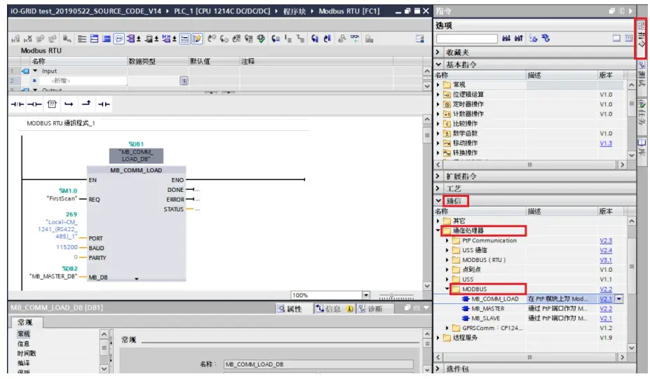
2.2 Siemens S7-1200 Connection Setup
- Launch the TIA Portal and select “Commands” on the right
 A. Click on the “Communication” menu
B. Click on the “Communication Processor” menu
C. Click on the “Modbus” menu
D. Click to add a new “MB_COMM_LOAD”
E. Click to add a new “MB_MASTER” - Connection method setup

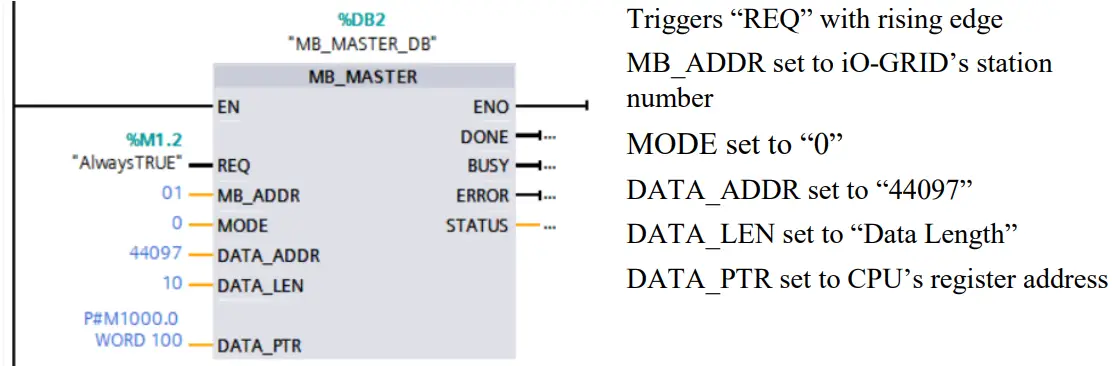
- Reading of the communication register

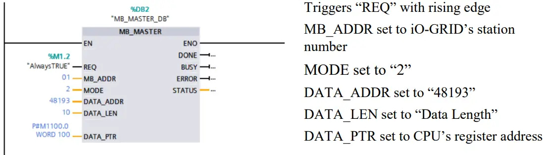
- Writing of the communication register

 A. Click on the “Communication” menu
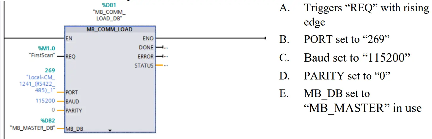
Notes:
※ ![]() ’s first GFDI-RM01N has the register address at 1000(HEX) converted to 4096(DEC)+1 and the starting address at 44097
’s first GFDI-RM01N has the register address at 1000(HEX) converted to 4096(DEC)+1 and the starting address at 44097
※ ![]() ’s first GFDO-RM01N has the register address at 2000(HEX) converted to 8192(DEC)+1 and the starting address at 48193
’s first GFDO-RM01N has the register address at 2000(HEX) converted to 8192(DEC)+1 and the starting address at 48193
※For MODE settings, please refer to Siemens DATA_ADDR & MODE Parameters


