
![]() DAUDIN CO., LTD.
DAUDIN CO., LTD.
2302EN
V2.0.0


and FATEK HMI Modbus TCP Connection
Operating Manual
1. Remote I/O Module System Configuration List
| Part No. | Specification | Description |
| GFGW-RM01N | Modbus TCP-to-Modbus RTU/ASCII, 4 Ports | Gateway |
| GFMS-RM01S | Master Modbus RTU, 1 Port | Main Controller |
| GFDI-RM01N | Digital Input 16 Channel | Digital Input |
| GFDO-RM01N | Digital Output 16 Channel / 0.5A | Digital Output |
| GFPS-0202 | Power 24V / 48W | Power Supply |
| GFPS-0303 | Power 5V / 20W | Power Supply |
1.1 Product Description
I. The gateway is used externally to connect with FATEK HMI communication port (Modbus TCP).
II. The main controller is in charge of the management and dynamic configuration of I/O parameters and so on.
III. The power module is standard for remote I/Os and users can choose the model or brand of power module they prefer.
2. Gateway Parameter Settings
This section details how to connect to FATEK HMI. For detailed information, please refer to the ![]() -Series Product Manual
-Series Product Manual
2.1 i-Designer Program Setup
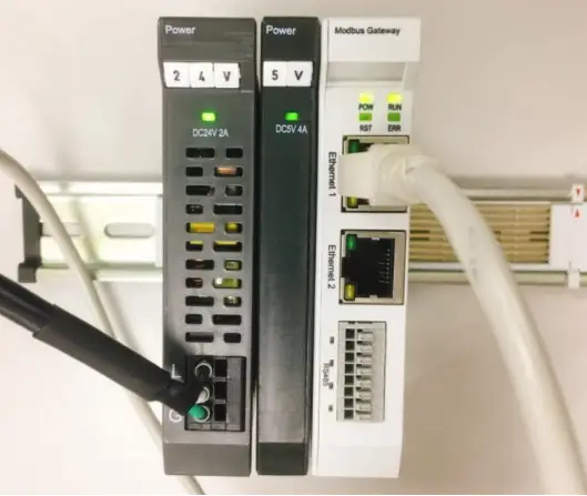
I. Make sure that the module is powered and connected to the gateway module using an Ethernet cable
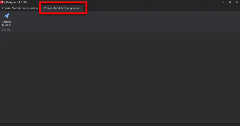
II. Click to launch the software

III. Select “M Series Module Configuration”
IV. Click on the “Setting Module” icon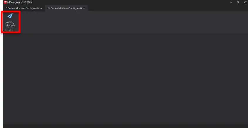
V. Enter the “Setting Module” page for M-series
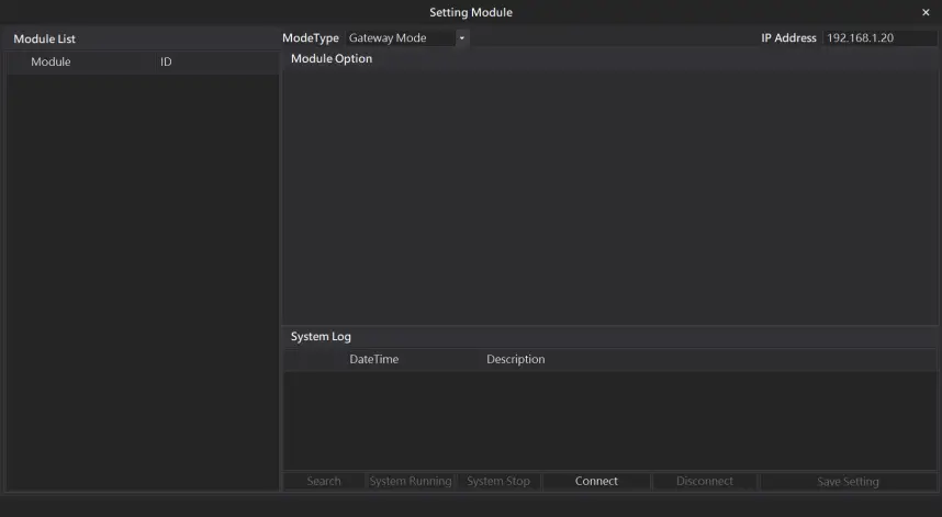
VI. Select the mode type based on the connected module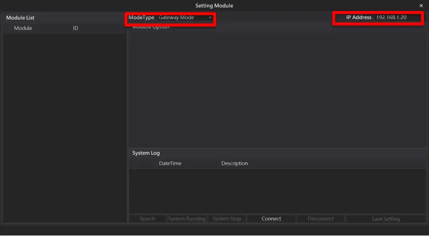
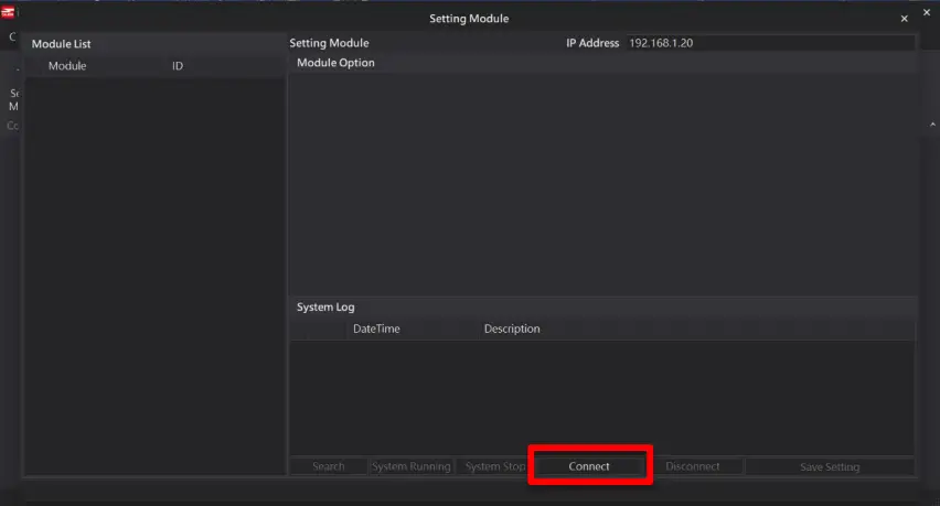
VII. Click on “Connect”
VIII. Gateway Module IP Settings
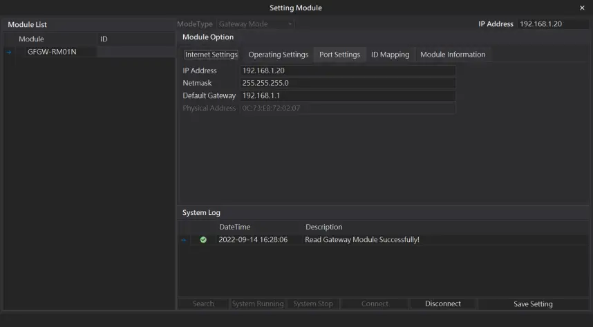
Note: The IP address must be in the same domain as the controller equipment
IX. Gateway Module Operational Modes
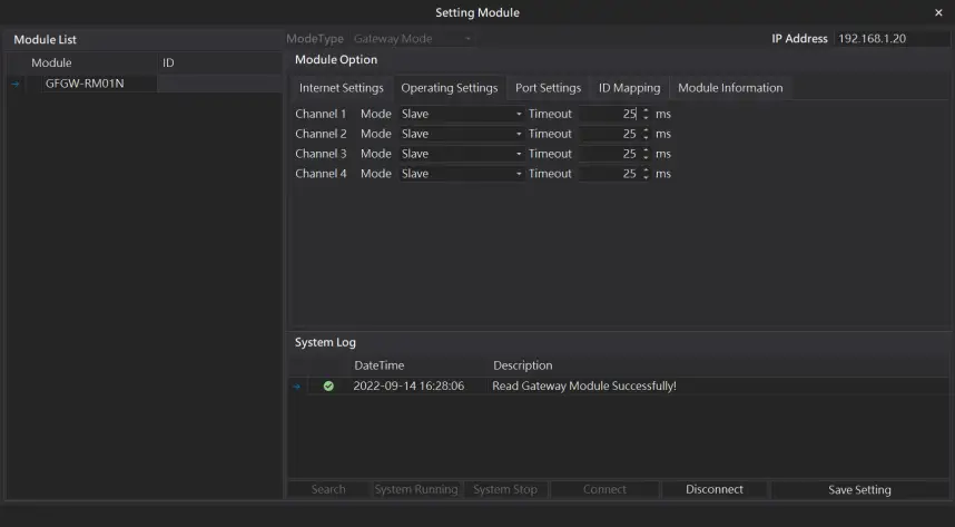
Note:
Set Group 1 as Slave and set the gateway to use the first set of RS485 port to connect to the main controller (GFMS-RM01N)
3. Beijer HMI Connection Setup
This chapter explains how to use the FvDesigner program to connect FATEK HMI with ![]() . For detailed information, please refer to FATEK FvDesigner User Manual
. For detailed information, please refer to FATEK FvDesigner User Manual
3.1 Beijer HMI Hardware Connection
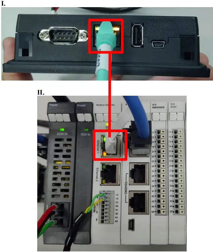
I. The connection port is on the right at the bottom of the machine.
II. Connect the port at the bottom of the machine to the gateway’s port
3.2 Beijer HMI IP Address and Connection Setup
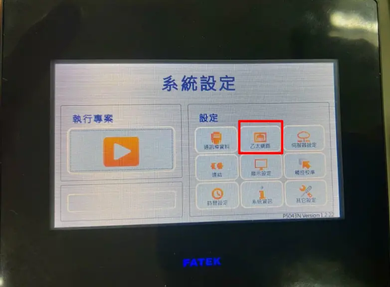
I. Once HMI is powered, press on the top-right and bottom-right areas on the HMI screen to enter the settings menu and then click on “Ethernet”.
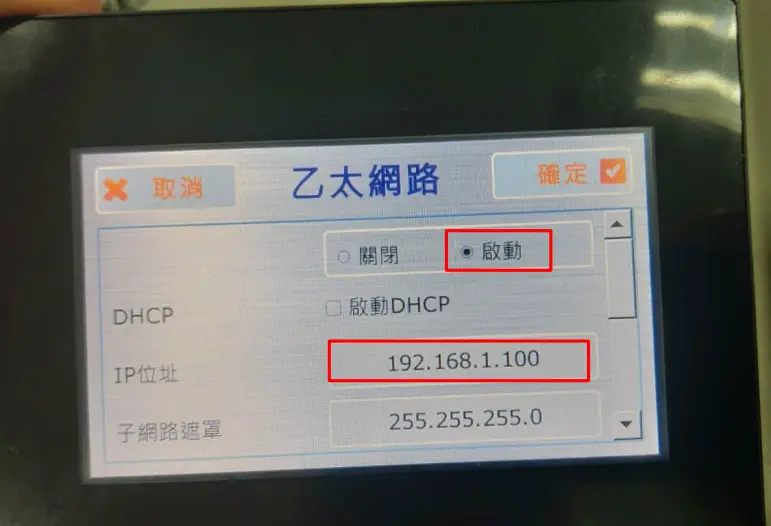
II. Click on “Activate” and set “IP Address” to the same domain as the gateway domain at 192.168.1.XXX.
III. Launch FvDesigner, open a new file, select the controller page and then click on “Add”
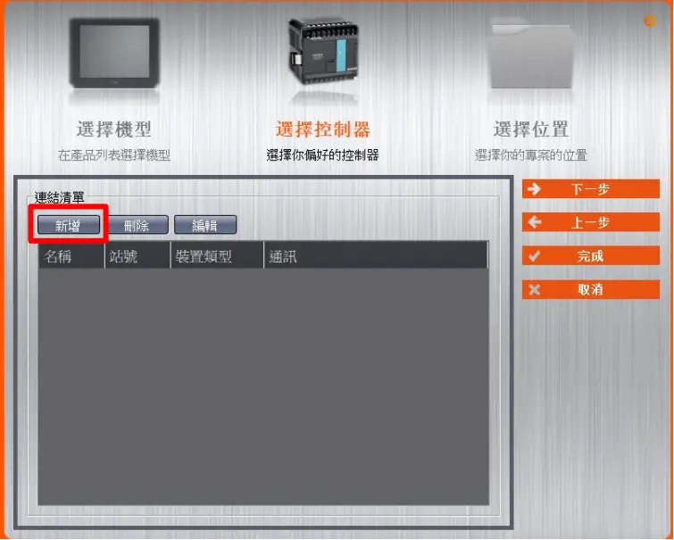
IV. Or you can click to open an existing file, select “Project Management” page and then click on “Connect”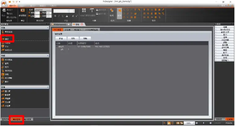
V. Connection method setup
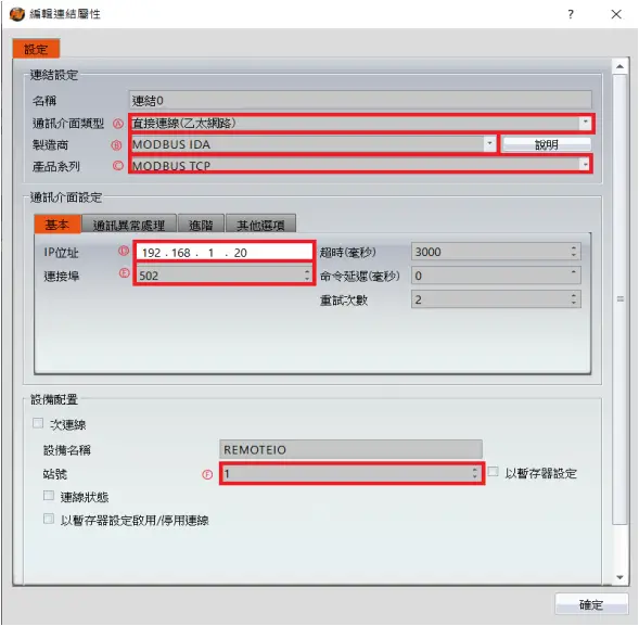
A From the “Communication Interface Type” drop-down menu, select “Connect Directly (Ethernet))”
B From the “Manufacturer” drop-down menu, select “MODBUS IDA”
C From the “Product Series” drop-down menu, select “MODBUS TCP”
D Set the IP address to the gateway’s default IP address
E Enter “502” for the connection port
F Set “Station No.” to the gateway’s default value
VI. Set up the location for the tag register
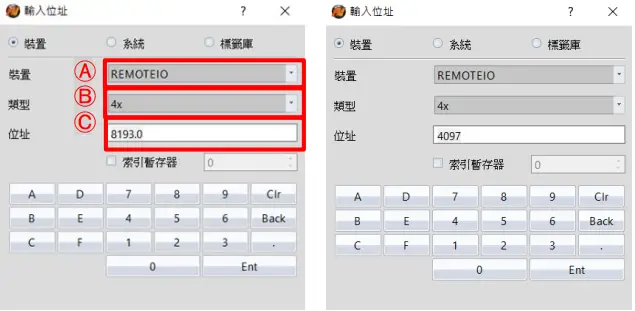
A From the “Device” drop-down menu, select the device to be connected
B From the “Type” drop-down menu, select “4x”
C Set up according to the plan
Example:
| IO-Grid_M register address | HMI’s corresponding address* | |
| R | 0x1000 | 4097 |
| R | 0x1001 | 4098 |
| R | 0x1000.0 | 4097.0 |
| W | 0x2000 | 8193 |
| W | 0x2001 | 8194 |
| W | 0x2000.0 | 8193.0 |
Note:
![]() HMI’s corresponding address is:
HMI’s corresponding address is:![]() ‘s first GFDI-RM01N has the register address at 1000(HEX) converted to 4096(DEC)+1
‘s first GFDI-RM01N has the register address at 1000(HEX) converted to 4096(DEC)+1
![]() ‘s first GFDO-RM01N has the register address at 2000(HEX) converted to 8192(DEC)+1
‘s first GFDO-RM01N has the register address at 2000(HEX) converted to 8192(DEC)+1
![]() Regarding
Regarding ![]() ‘s register address and format, please refer to
‘s register address and format, please refer to ![]() Control Module Operating Manual
Control Module Operating Manual


