![]()
![]() Delta PLC Modbus RTU Connection
Delta PLC Modbus RTU Connection
User Manual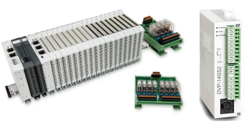 2302EN
V1.0.0
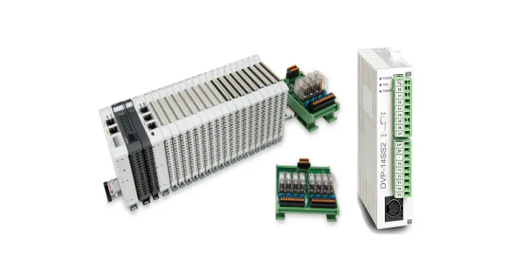
![]() and Delta PLC
and Delta PLC
Modbus RTU Connection
Operating Manual
Remote I/O Module System Configuration List
| Part No. | Specification | Description |
| GFMS-RM01S | Master Modbus RTU, 1 Port | Main Controller |
| GFDI-RM01N | Digital Input 16 Channel | Digital Input |
| GFDO-RM01N | Digital Output 16 Channel / 0.5A | Digital Output |
| GFPS-0202 | Power 24V / 48W | Power Supply |
| GFPS-0303 | Power 5V / 20W | Power Supply |
| 0170-0101 | 8 pin RJ45 female connector/RS-485 Interface | Interface Module |
1.1 Product Description
I. The interface module is used externally to convert Delta PLC RS485’s communication port (Modbus RTU) to a RJ45 connector
II. The main controller is in charge of the management and dynamic configuration of I/O parameters and so on.
III. The power module and interface module are standard for remote I/Os and users can choose the model or brand they prefer.
Delta PLC Connection Setup
This chapter explains how to use the ISPSoft program to connect Delta PLC with ![]() .
.
For detailed information, please refer to ISPSoft User Manual
2.1 Delta PLC Hardware Connection
I. The connection port is at the bottom of the machine. Using DVP-14SS2 for demonstration, connect Port 2(RS485 A/B) to the interface module (1/2) to convert it into a RJ45 connection, which will be connected to the main controller.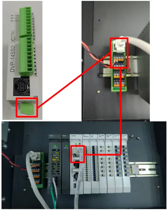 2.2 Delta PLC Connection Setup
I. Launch ISPSoft and set COM2’s communication settings to the RTU mode, 115200bps, 8 data bits, None parity and 1 stop bits (115200, 8,N, 1). Programming Example: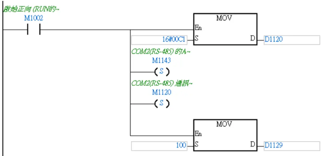 ※The communication parameter setting must be consistent with
 ![]() to enable communication
to enable communication
II. Use the MODRW command to setup the reading/writing of ![]() ’s I/O module
’s I/O module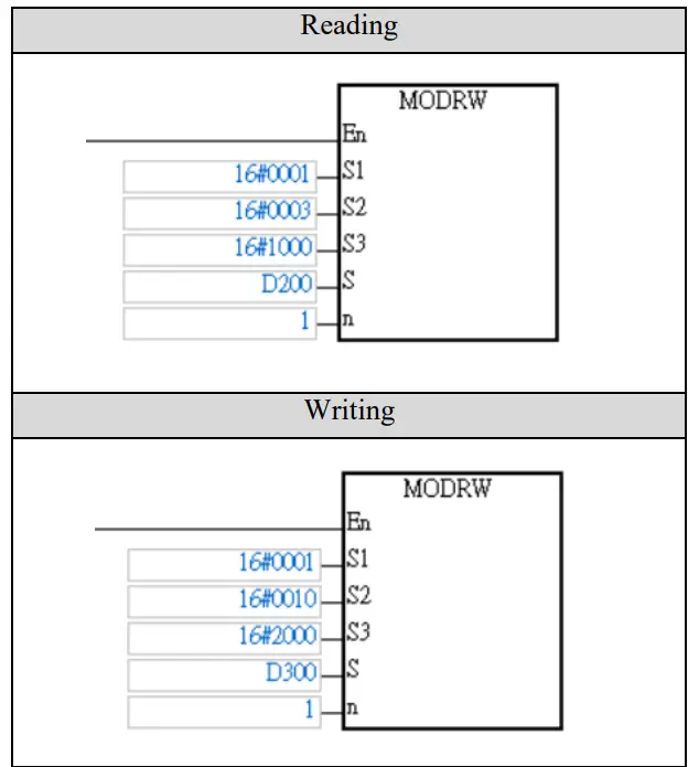 S1: Connected device addresses: K1~K254
S2: Communication function code
S3: The address where data will be read/written
S: The register where the data to be read/written is tored
N: Length of the data to be read/written
※![]() ’s first GFDI-RM01N has the register address at 1000(HEX)
’s first GFDI-RM01N has the register address at 1000(HEX)
※![]() ’s first GFDO-RM01N has the register address at 2000(HEX)
’s first GFDO-RM01N has the register address at 2000(HEX)
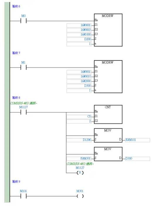
※Note: When using the read command, please use register D1296 to start using the stored data
Use the “read” command above to set up D200 to read 2 registers with first point of DI as the example.
| Register | DATA | Description | |
| D200 (Low- order byte) | “0” | ADR 1 ADR 0 | |
| D200 (Highoder byte) | |||
| D201 (Low- order byte) | CM D 3 C MD 0 | ||
| D201 (High- order byte) | “3” | ||
| D202 (Low- order byte) | 44044 | Data Bytes | |
| D202 (High- order byte) | “2” | ||
| D203 (Low- order byte) | 44044 | Content at the address 2100 I-1 | PLC will automatically convert ASCII characters into values and store them at D1296=H0001 |
| D203 up | 4,019 | ||
| D204 down | 44044 | ||
| D204 up | 4414, | ||
| D205 down | 440,4 | Content at the address 2101 1-1 | PLC will automatically convert ASCII characters into values and store them at D1297=1-10000 |
| D205 up | 44044 | ||
| D206 down | 4404, | ||
| D206 up | 440,4 | ||
| D207 down | LRC CHK 1 | ||
| D207 up | LRC CHK 0 | ||
Based on this table, users can use D1296 register to read the entire data (Word).
III. rogramming Example:
This example is for communications and using RS485 communication to read/write![]() module
module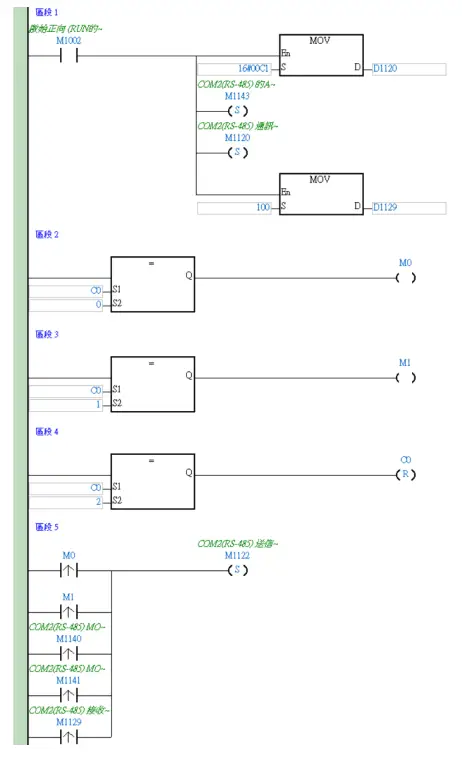
![]()


