
DELTA uno Lite Modbus

Revision
| Date | Version | Description |
| 2022/ 11 / 11 | 0.1 | Initial Version |
Overview
UNOlite is an indoor air quality monitor to measure the space temperature / humidity / CO2 / PM2.5 / PM10 / PM1 / TVOC and expose the measurements directly onto a BACnet MS/TP or Modbus RTU network. Moreover, the measurements are also accessible with UNO apps through BLE or UNO web through Wi-Fi (Wi-Fi model). Please refer to UNOlite official website for more information. This document is primarily concerned how to add UNOlite to Modbus/RTU network.
Hardware Interface
Buttons
| Key | Description |
| Hardware reset | Push this button will trigger a power cycle. |
|
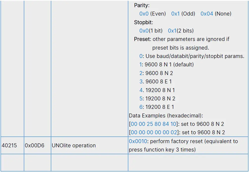
Factory reset | After booting, press this button three times within 2 seconds will trigger factory reset. The values below will be restored to default: s Modbus baudrate s BACnet saved mac address s Wi-Fi MQTT broker setting (Wi-Fi model) |
NOTE: /t’s recommended to use a paper clip to press the keys.
Terminal block
| Terminal | Description |
| V+ | Power input. For more information, please refer to production specification. |
| V- | Power input. For more information, please refer to production specification. |
| A+ | RS485(+) data pin. For Modbus/BACnet network. |
| B- | RS485(-) data pin. For Modbus/BACnet network. |
| GND | Ground terminal. Each RS485 driver in an installation is recommended to connect to the same ground to get a common reference. |
DIP switch
| DIPs | Description | ON | OFF |
| 1 – 6 | Refer to the later sections for the definition of each pin | n | |
| 7 | BACnet mode switch. ON : BACnet mode OFF : Modbus mode | n | |
| 8 | RS485 terminator resistor (120 ohm) | n |
NOTE The dips should be adjusted to proper position in power off state. Adjust the dips, then power on device.
Modbus Mode
UNOlite follows Modbus over serial line specification and will run on Modbus/RTU mode if the 7th pin is set to OFF state. The definition of the dips in Modbus mode as listed below:
| DIP | Description | ON | OFF |
| 1 | Modbus slave address (check address table) | n | |
| 2 | Modbus slave address (check address table) | n | |
| 3 | Modbus slave address (check address table) | n | |
| 4 | Modbus slave address (check address table) | n | |
| 5 | Modbus slave address (check address table) | n |
- NOTE: The definitions of dip are different from Modbus mode. Please make sure which mode is chosen.
- NOTE: Pin6 is not defined in Modbus mode
Serial Configuration
UNOlite can directly connect to a controller with RS485 interface, up to 32 UNOlite devices can be joined to a Modbus serial bus.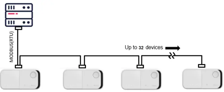
NOTE: Suggestion to use 22AWG shielded twisted pair cable to connect devices in sequence
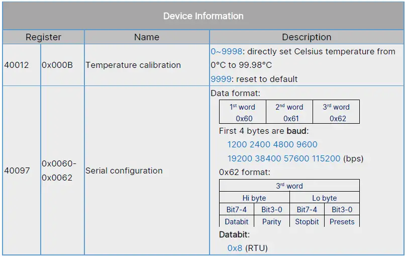
Default Serial Configuration:
- Baud: 9600
- Data-Bit: 8
- Parity: None
- Stop-Bit: 1
Note: perform factory reset to restore default value if the configuration is missing
Modbus Slave Address
The DIP pins 1~5 represent for binary number 0~31, pin 1 is most significant bit (MSB) and pin 5 is least significant bit (LSB). Notice that Modbus slave address starts from 208, therefore, UNOlite can be configured address from 208 to 239:
Modbus Slave Address Table
| DIP pin | Modbus Slave Addr | DIP pin | Modbus Slave Addr | |||||||||
| 1 | 2 | 3 | 4 | 5 | 1 | 2 | 3 | 4 | 5 | |||
| ↓ | ↓ | ↓ | ↓ | ↓ | 208 (0xD0) | ↑ | ↓ | ↓ | ↓ | ↓ | 224 (0xE0) | |
| ↓ | ↓ | ↓ | ↓ | ↑ | 209 (0xD1) | ↑ | ↓ | ↓ | ↓ | ↑ | 225 (0xE1) | |
| ↓ | ↓ | ↓ | ↑ | ↓ | 210 (0xD2) | ↑ | ↓ | ↓ | ↑ | ↓ | 226 (0xE2) | |
| ↓ | ↓ | ↓ | ↑ | ↑ | 211 (0xD3) | ↑ | ↓ | ↓ | ↑ | ↑ | 227 (0xE3) | |
| ↓ | ↓ | ↑ | ↓ | ↓ | 212 (0xD4) | ↑ | ↓ | ↑ | ↓ | ↓ | 228 (0xE4) | |
| ↓ | ↓ | ↑ | ↓ | ↑ | 213 (0xD5) | ↑ | ↓ | ↑ | ↓ | ↑ | 229 (0xE5) | |
| ↓ | ↓ | ↑ | ↑ | ↓ | 214 (0xD6) | ↑ | ↓ | ↑ | ↑ | ↓ | 230 (0xE6) | |
| ↓ | ↓ | ↑ | ↑ | ↑ | 215 (0xD7) | ↑ | ↓ | ↑ | ↑ | ↑ | 231 (0xE7) | |
| ↓ | ↑ | ↓ | ↓ | ↓ | 216 (0xD8) | ↑ | ↑ | ↓ | ↓ | ↓ | 232 (0xE8) | |
| ↓ | ↑ | ↓ | ↓ | ↑ | 217 (0xD9) | ↑ | ↑ | ↓ | ↓ | ↑ | 233 (0xE9) | |
| ↓ | ↑ | ↓ | ↑ | ↓ | 218 (0xDA) | ↑ | ↑ | ↓ | ↑ | ↓ | 234 (0xEA) | |
| ↓ | ↑ | ↓ | ↑ | ↑ | 219 (0xDB) | ↑ | ↑ | ↓ | ↑ | ↑ | 235 (0xEB) | |
| ↓ | ↑ | ↑ | ↓ | ↓ | 220 (0xDC) | ↑ | ↑ | ↑ | ↓ | ↓ | 236 (0xEC) | |
| ↓ | ↑ | ↑ | ↓ | ↑ | 221 (0xDD) | ↑ | ↑ | ↑ | ↓ | ↑ | 237 (0xED) | |
| ↓ | ↑ | ↑ | ↑ | ↓ | 222 (0xDE) | ↑ | ↑ | ↑ | ↑ | ↓ | 238 (0xED) | |
| ↓ | ↑ | ↑ | ↑ | ↑ | 223 (0xDF) | ↑ | ↑ | ↑ | ↑ | ↑ | 239 (0xEF) | |
Modbus Read Data
UNOlite supports function code both 0x03 and 0x04 to read following registers
- 0x03: read holding registers
- 0x04: read input registers
Request Slave Address 1 byte
Function code 1 byte
Register 2 bytes
Length [N] 2 bytes
CRC16 2 bytes
Response Slave Address 1 byte
Function code 1 byte
Count [2*N] 1 byte
Data N * 2 bytes
CRC16 2 bytes
Sensor Measurement Register Name Description 30001
0x0000
IAQ index
Give an index according to current PM2.5, PM10, and CO2 concentration. The index also be referenced by IAQ LED: GREEN: 0~80 YELLOW: 81~100 RED: 101~400 PURPLE: 401~
30002 0x0001 Concentration of PM2.5 Unit: μg/m3 30003 0x0002 Concentration of PM10 Unit: μg/m3 30004 0x0003 Concentration of carbon dioxide (formula CO2)
Unit: ppm 30005 0x0004 Concentration of total volatile organic compound (TVOC)
Unit: ppb 30006 0x0005 Concentration of total volatile organic compound (TVOC)
Unit: μg/m3 (factor 1 ppb = 4.5 μg/m3) 30009 0x0008 Humidity Unit: 0.01% 30011 0x000A Celsius temperature Real Temp = (Value – 4500) * 0.01 Unit: °C
30018 0x0011 Fahrenheit temperature Real Temp = (Value – 4500) * 0.01 Unit: °F
30020 0x0013 Concentration of PM1 Unit: μg/m3 Sensor State Register Name Description 30033
0x0020
PM2.5 sensor
State of sensor hardware module 0x0000: Power off or does not exist 0x0001: Sensor Ready
0x0002: Warming up 0x0003: Busy 0x00FE: CSERROR
0x00FF: FAIL
30034
0x0021
PM10 sensor
30035
0x0022
CO2 sensor
30036
0x0023
TVOC sensor
30037
0x0024
Humidity sensor
30038
0x0025
Temperature sensor
30042
0x0029
PM1 sensor
30044
0x002B
IAQ LED state
0x0000: LED off 0x0001: LED on
Device Information Register Name Description 30145
0x0090- 0x009F
Model and Product Serial Number An ASCII string consists model name and serial number, separated by a comma. For example: “UNO-L,2250L01F9999”
30209 0x00D0 Main firmware version Number 1 to 65535 0x0000: device is initializing
30257 0x0100- 0x0102
BT MAC address 6 groups of two hexadecimal digits, e.g. F2:11:8F:36:F6:93
30260 0x0103- 0x0105
WIFI MAC address 6 groups of two hexadecimal digits
Modbus Write Command
UNOlite supports function code 0x06 and 0x10 to write request
0x06: write single register
| Request | ||||
| Address 1 byte | Function code 1 byte | Register 2 bytes | Data 2 bytes | CRC16 2 bytes |
| Response | ||||
| Address 1 byte | Function code 1 byte | Register 2 bytes | Data 2 bytes | CRC16 2 bytes |
0x10: write multiple registers
| Request | ||||||||||
| Address 1 byte | Fn. Code 1 byte | Register 2 bytes | Length[N] 2 bytes | Count[2*N] 1 byte | Data N * 2 bytes | CRC16 2 bytes | ||||
| Response | ||||||||||
| Address 1 byte | Function code 1 byte | Register 2 bytes | Length [N] 2 bytes | CRC16 2 bytes | ||||||
Modbus Examples
- Read all sensor status from device 208 (0xD0)
Request D0 03 00 20 00 0B 17 86 Response D0 03 16 00 01 00 01 00 01 00 01 00 01 00 01 00 FE 00 FE 00 FF 00 00 00 01 60 8F
- Read firmware version from device 208 (0xD0)
Request D0 03 00 D0 00 01 97 B2 Response D0 03 02 00 04 45 95 - Set rs485 serial configuration, 115200-8-N-1
Request D0 10 00 60 00 03 06 00 01 C2 00 84 00 BB 56 Response D0 10 00 60 00 03 92 57
Modbus Exception Response
If device receives a request message without a communication error, but cannot handle the query. It will reply with requested function code plus 0x80. Example, function code 0x3 becomes 0x83
Response format
| Address 1 byte | Function code 1 byte | Code 1 bytes | CRC16 2 bytes |
Code list
| Code | Name |
| 0x01 | ILLEGAL FUNCTION |
| 0x02 | ILLEGAL DATA ADDRESS |
| 0x03 | ILLEGAL DATA VALUE |
| 0x04 | SERVER DEVICE FAILURE |
| 0x05 | ACKNOWLEDGE |
| 0x06 | SERVER DEVICE BUSY |
| 0x08 | MEMORY PARITY ERROR |
| 0x0A | GATEWAY PATH UNAVAILABLE |
| 0x0B | GATEWAY TARGET DEVICE FAILED TO RESPOND |
Note: Please refer to “ModbUs Application_Protocol_V1_1b3” from www.modbus.org


