DELTA RTU-485 Modbus Remote I-O Communication Module
Product Information
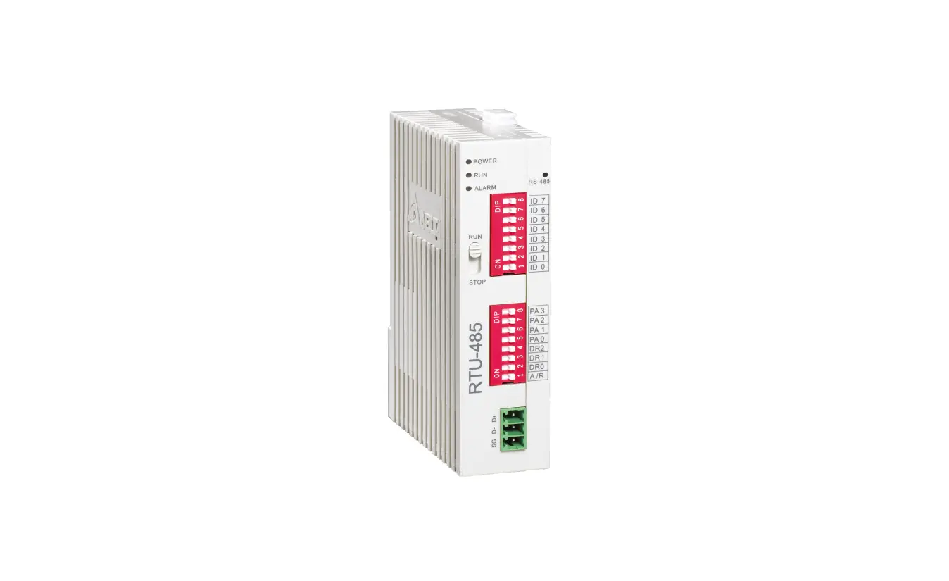
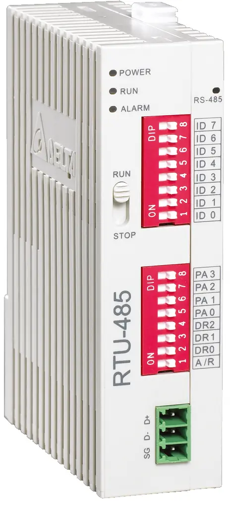
Modbus Remote I/O Communication Module RTU-485
The Modbus Remote I/O Communication Module RTU-485 is a product designed to remotely control DVP Slim series I/O modules using Delta’s PLC. It is a standard Modbus slave device and is compatible with other master devices which comply with the Modbus protocol. The device has an auto-detecting I/O module feature, and the maximum extension is 8 special I/O modules, 128 input points, and 128 output points for digital I/O modules. The device has a 24VDC power supply (with DC input polarity reverse protection).
Features
- Auto-detecting I/O modules
- Maximum extension: 8 special I/O modules; 128 input points and 128 output points for digital I/O modules
Specifications
- DeviceNet connection
- Transmission method: RS-485
- Electrical isolation: 500 VDC
- Interface: Removable connector (3Pin)
- Transmission cable: 2-wire twister shielded cable
- Communication mode: RTU, ASCII
- Baud rates: 1,200bps; 2,400bps; 4,800bps; 9,600bps; 19,200bps; 38,400bps; 57,600bps; 115,200bps
- Noise immunity:
- ESD (IEC 61131-2, IEC 61000-4-2): 8KV Air Discharge, 4KV Contact Discharge
- EFT (IEC 61131-2, IEC 61000-4-4): Power Line: 2KV, Digital I/O: 1KV, Analog & Communication I/O: 1KV, Damped-Oscillatory Wave: Power Line: 1KV, Digital I/O: 1KV
- RS (IEC 61131-2, IEC 61000-4-3): 80MHz~1000MHz , 1.4GHz~2.0GHz , 10V/m
Product Usage Instructions
Before using the Modbus Remote I/O Communication Module RTU-485, it is important to read the manual carefully and follow the instructions to prevent damage to the device or injuries to staff.
Basic Operation
Switch off the power before wiring. The RTU-485 is an OPEN TYPE device and therefore should be installed in an enclosure free of airborne dust and humidity. The following steps should be followed for basic operation:
- Connect RTU-485 to DVP Slim DI/DO Extension Unit
- Install RTU-485 and DVP Slim DI/DO on DIN Rail
Function Codes RTU-485 Supports
The RTU-485 supports the following function codes:
- 01: Read Coil Status
- 02: Read Input Status
- 03: Read Holding Registers
- 04: Read Input Registers
- 05: Force Single Coil
- 06: Preset Single Register
- 0F: Force Multiple Coils
- 10: Preset Multiple Registers
Application of RTU-485
The RTU-485 can be used in the following applications:
- Connection between RTU-485 and Master Device
- Application Example
Introduction
- To ensure correct installation and operation of RTU-485, please read this chapter carefully before using your RTU-485
- RTU-485 is a Modbus remote I/O communication module for Delta’s PLC to remote-control DVP Slim series I/O modules.
- RTU-485 is a standard Modbus slave device and is compatible with pther master devices which comply with Modbus protocol.
Features
- Auto-detecting I/O modules
- Maximum extension: 8 special I/O modules; 128 input points and 128 output points for digital I/O modules
Specifications
- DeviceNet connection
Transmission method RS-485 Electrical isolation 500 VDC Interface Removable connector (3Pin) Transmission cable 2-wire twister shielded cablew8 - Communication
Mode
ASCII
7, E, 1 7, O, 2 8, O, 1 7, O, 1 7, N, 2 8, N, 1 7, E, 2 8, E, 1 8, N, 2 RTU 8, E, 1 8, O, 1 8, N, 1 8, N, 2 Baud rates 1,200bps; 2,400bps; 4,800bps; 9,600bps; 19,200bps; 38,400bps; 57,600bps; 115,200bps - Electrical specification
Power supply 24 VDC (-15% ~ 20%) (with DC input polarity reverse protection) - Environment
Noise immunity
ESD (IEC 61131-2, IEC 61000-4-2): 8KV Air Discharge,4KV Contact Discharge EFT (IEC 61131-2, IEC 61000-4-4): Power Line: 2KV, Digital I/O: 1KV
Analog & Communication I/O: 1KV
Damped-Oscillatory Wave: Power Line: 1KV, Digital I/O: 1KV
RS (IEC 61131-2, IEC 61000-4-3): 80MHz~1000MHz , 1.4GHz~2.0GHz ,
10V/m
Operation 0ºC ~ 55ºC (temperature); 50 ~ 95% (humidity); pollution degree 2 Storage -25ºC ~ 70ºC (temperature); 5 ~ 95% (humidity) Vibration/shock resistance Standard: IEC 61131-2、IEC 68-2-6 (TEST Fc)/IEC 61131-2 & IEC 68-2-27 (TEST Ea) Certificates IEC 61131-2, UL508
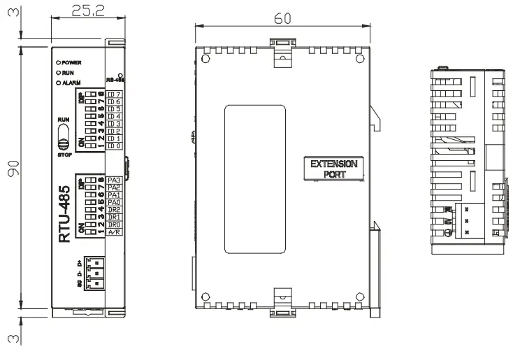
Product Profile & Outline
Dimension
Product Profiles
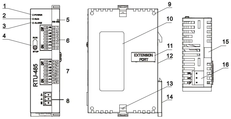
- POWER indicator
- RUN indicator
- ALARM indicator
- RUN/STOP switch
- Communication indicator
- Address switch
- Communication mode switch
- RS-485 communication port
- Mounting hole for I/O module
- Nameplate
- I/O module connection port
- DIN rail (35mm)
- Fastening hole for I/O module
- DIN rail clip
- Mounting rail for I/O module
- Power input
RUN/STOP Switch
| RUN/STOP action | Explanation |
| RUN | I/O module in RUN mode |
| RUN → STOP | 1. I/O module switches from RUN to STOP. 2. Output points on digital I/O module all turn Off. |
| STOP | 1. Special I/O module in STOP mode 2. Special I/O module cannot be controlled by communication. 3. Digital I/O module cannot be controlled by communication. |
| STOP → RUN | 1. Special I/O module switches from STOP to RUN. 2. RTU-485 redetects the number of points in Slim DI/DO and the number of special I/O modules. |
Address Switch
The switch is used on setting up the communication address of RTU-485. Range: H’01 ~ H’F0 (decimal: 1 ~ 240)
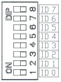
| Switch setting | Content |
| H’01 ~ H’F0 | Valid communication address ID0 ~ ID7 are defined as: 20, 21, 22, …26, 27 |
| H’00, H’F1 ~ H’FF | Invalid communication address |
Example: If you need to set the address of RTU-485 to 26, swich the DIP switch corresponding to ID4 to “ON”, switch corresponding to ID3 to “ON” and switch corresponding to ID1 to “ON”.
Note:
- Please set up the address when the power of RTU-485 is switched off. After the setup is completed, re-power RTU-485.
- When RTU-485 is operating, changing the setting of communication address will be invalid.
- Use slotted screwdriver to adjust the switch carefully in case you scratch the switch.
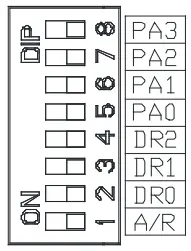
Communication Mode Switch
These switches are for:
- Setting up communication format (PA0 ~ PA3, A/R)
- Setting up baud rate (DR0 ~ DR2)

PA3 PA2 PA1 PA0 A/R Format OFF OFF OFF OFF ON 7,E,1, ASCII OFF OFF OFF ON ON 7,O,1, ASCII OFF OFF ON OFF ON 7,E,2, ASCII OFF OFF ON ON ON 7,O,2, ASCII OFF ON OFF OFF ON 7,N,2, ASCII OFF ON OFF ON ON 8,E,1, ASCII OFF ON ON OFF ON 8,O,1, ASCII OFF ON ON ON ON 8,N,1, ASCII ON OFF OFF OFF ON 8,N,2, ASCII OFF ON OFF ON OFF 8,E,1, RTU OFF ON ON OFF OFF 8,O,1, RTU OFF ON ON ON OFF 8,N,1, RTU ON OFF OFF OFF OFF 8,N,2, RTU DR2 DR1 DR0 Baud rate (bps) OFF OFF OFF 1,200 OFF OFF ON 2,400 OFF ON OFF 4,800 OFF ON ON 9,600 ON OFF OFF 19,200 ON OFF ON 38,400 ON ON OFF 57,600 ON ON ON 115,200
Note:
- Please set up the switch when the power is switched off. After the setup is completed, re-power RTU-485.
- When RTU-485 is operating, changing the setting of the switch will be invalid.
- Use slotted screwdriver to adjust the switch carefully in case you scratch the switch.
Basic Operation
Connecting RTU-485 to DVP Slim DI/DO Extension Unit
- Open the fixing clips on top and bottom of RTU-485. Meet the extension port of Slim DI/DO with RTU-485.
- Press the fixing clips on top and bottom of Slim DIDO and check if the connection is fine.

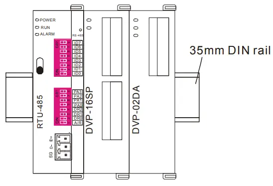
Installing RTU-485 and DVP Slim DI/DO on DIN Rail
- Use 35mm DIN rail.
- Open the DIN rail clip on RTU-485 and Slim DI/DO. Insert RTU-485 and Slim DI/DO onto the DIN rail.
- Clip up the DIN rail clips on RTU-485 and Slim DI/DO to fix them on the DIN rail, as shown below.

Areas for Special Functions
Areas in Digigal I/O Module
| Communication address | Devices | Attribute | Data type | Length |
| H’0400 ~ H’047F | X: X000 ~ X177 (Octal) | R | bit | 128 points |
| H’0500 ~ H’057F | Y: Y000 ~ Y177 (Octal) | R/W | bit | 128 points |
Areas in Special I/O Module
| Communication address | Devices | Attribute | Data type | Length |
| H’1600 ~ H’1630 | 1st special I/O module: CR0 ~ CR48 |
Please refer to theCR attribute of each special I/O module. | word | 49 |
| H’1640 ~ H’1670 | 2nd special I/O module: CR0 ~ CR48 | word | 49 | |
| H’1680 ~ H’16B0 | 3rd special I/O module: CR0 ~ CR48 | word | 49 | |
| H’16C0 ~ H’16F0 | 4th special I/O module: CR0 ~ CR48 | word | 49 | |
| H’1700 ~ H’1730 | 5th special I/O module: CR0 ~ CR48 | word | 49 | |
| H’1740 ~ H’1770 | 6th special I/O module: CR0 ~ CR48 | word | 49 | |
| H’1780 ~ H’17B0 | 7th special I/O module: CR0 ~ CR48 | word | 49 | |
| H’17C0 ~ H’17F0 | 8th special I/O module: CR0 ~ CR48 | word | 49 |
Note: Maximum 8 special I/O modules are connectible to RTU-485. The first special module connected is the
nearest one on the right hand side of RTU-485, and so on.
Special Functions
| Communication address | Attribute | Content | Explanation |
| H’0000 | R | Model name | Set up by the system. Model code of RTU-485 = H’0200. |
| H’0001 | R | Firmware version | The current firmware version is displayed in hex, e.g. V0.1 is indicated as H’0010. |
| H’0002 | R | Issue date | The issue data of the firmware is displayed in hex, e.g. H’1FD0 = K8150 indicates that the firmware is issued on the morning of August 15. |
| H’0003 | R/W | RUN/STOP RTU-485 | H’0003 = K1, RTU-485 RUN; H’0003 = K0, RTU-485 STOP. |
| H’0004 | R | Communication format | Displaying the communication format of RTU-485. |
| H’0005 | R | Baud rate | Displaying the baud rate of RTU-485. |
| H’0006 | R | Communication address | Displaying the communication address of RTU-485. |
| H’0007 | R | Number of DI/DO points | High byte stores the number of input points. Low byte stores the number of output points. |
| H’0008 | R | Error code | Recording the current error. See 17.4.4 for the meaing of error codes. |
| H’0009 | R | Historical error code | The number of errors occurring. Range: 0 ~ 32 |
| H’0017 | R | Number of special I/O modules | The number of special I/O modules RTU-485 detects. |
| H’0018 | R | Model code of the 1st special I/O module | The model code of the 1st special I/O module connected to RTU-485. |
| H’0019 | R | Model code of the 2nd special I/O module | The model code of the 2nd special I/O module connected to RTU-485. |
| H’001A | R | Model code of the 3rd special I/O module | The model code of the 3rd special I/O module connected to RTU-485. |
| H’001B | R | Model code of the 4th special I/O module | The model code of the 4th special I/O module connected to RTU-485. |
| Communication address | Attribute | Content | Explanation |
| H’001C | R | Model code of the 5th special I/O module | The model code of the 5th special I/O module connected to RTU-485. |
| H’001D | R | Model code of the 6th special I/O module | The model code of the 6th special I/O module connected to RTU-485. |
| H’001E | R | Model code of the 7th special I/O module | The model code of the 7th special I/O module connected to RTU-485. |
| H’001F | R | Model code of the 8th special I/O module | The model code of the 8th special I/O module connected to RTU-485. |
Error Codes
| Code | Indication | Explanation |
| 0001 | Incorrect function code | RTU-485 does not support this function code. |
| 0002 | Incorrect operand address | The address of a certain device is not within the range, orthe data written into it are incorrect. |
| 0003 | Incorrect data | The data read/written exceed the maximum length. |
| 0004 | RTU-485 STOP | RTU-485 in STOP mode. |
| 000B | Incorrect communication format | The length of data received by RTU-485 is too short. |
| 000C | Incorrect communication format | The length of data received by RTU-485 is too long. |
Function Codes RTU-485 Supports
RTU-485 complies with the standard Modbus protocol, supporting 7 function codes, which are H’01, H’02, H’03, H’05, H’06, H’0F and H’10. Please refer to the standard Modbus protocol for the specific data format of each function code.
| Code | Function | Data type | Applicable address |
| H’01 | Reading the output status of bit device. | bit | DO area: H’0500 ~ H’057F |
| H’02 | Reading the input status of bit device | bit | DI area: H’0400 ~ H’047F |
|
H’03 |
Reading register |
word | Area for special functions: H’0000 ~ H’001F |
| CR for the 1st special I/O module: H’1600 ~ H’1630 | |||
| CR for the 2nd special I/O module: H’1640 ~ H’1670 | |||
| CR for the 3rd special I/O module: H’1680 ~ H’16B0 | |||
| CR for the 4th special I/O module: H’16C0 ~ H’16F0 | |||
| CR for the 5th special I/O module: H’1700 ~ H’1730 | |||
| CR for the 6th special I/O module: H’1740 ~ H’1670 | |||
| CR for the 7th special I/O module: H’1780 ~ H’16B0 | |||
| CR for the 8th special I/O module: H’17C0 ~ H’17F0 | |||
| H’05 | Writing single datum into bit device | bit | DO area: H’0500 ~ H’057F |
| H’06 | Writing single datum into register | word | RTU-485 RUN/STOP mode: H’0003 |
| Applicable to CR with R/W attribute in the 1st ~ 8th special I/O module | |||
| H’0F | Writing multiple data into bit device | bit | DO area: H’0500 ~ H’057F |
| H’10 | Writing multiple data into register | word | Applicable to CR with R/W attribute in the 1st ~ 8th special I/O module |
Application of RTU-485
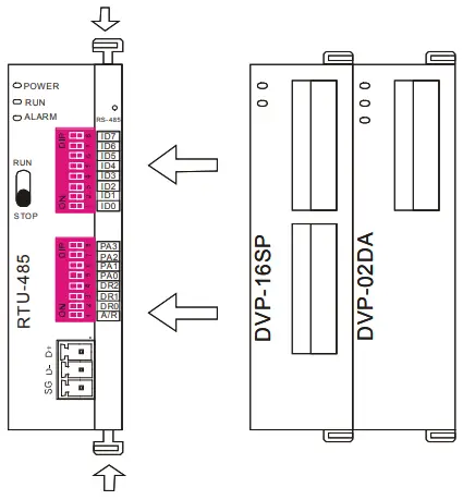
Connection between RTU-485 and Master Device
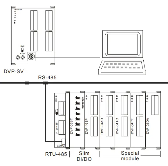
As a standard Modbus slave, RTU-485 is compatible with pther programmable logic controllers which also comply with Modbus protocol. The example here takes DVP-SV PLC as the master. The PC downloads the ladder diagram to DVP-SV through RS-232 communication port (COM1). When DVP-SV executes the ladder diagram program, it will send out Modbus command through RS-485 communication port (COM2) and conduct remote I/O control on RTU-485. See the figure on the next page for the connection between RTU-485 and the master device:
Application Example
- Example 1
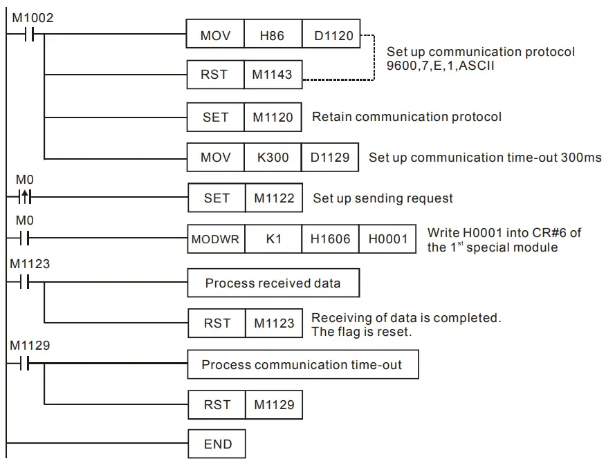
- The station No. of RTU-485 is “1”. Write “H’0001” into CR#6 of the 1st special I/O module

- The station No. of RTU-485 is “1”. Write “H’0001” into CR#6 of the 1st special I/O module
- Explanations
- You have to set up the communication format at the beginning of the program. The communication format for the master and slave has to be consistent, e.g. you can see the format is 9600, 7, E, 1, ASCII from this example.
- After setting up the communication format, you have to set up the communication retention device M1120 of COM2.
- After M0 is On, set up the sending request flag, and the master device will send out a request message to RTU-485 and write H’0001 into CR#6 of the 1st special module on the right hand side of RTU-485.
- Example 2
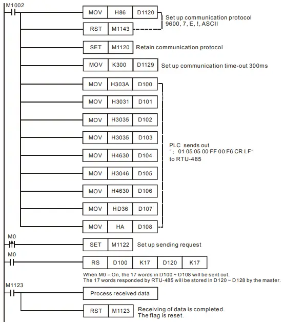
- The station No. of RTU-485 is “1”. Set up Y0 of the Slim DI/DO on the right hand side of RTU-485.


- The station No. of RTU-485 is “1”. Set up Y0 of the Slim DI/DO on the right hand side of RTU-485.
LED Indicator & Trouble-shooting
There are four LED indicators on RTU-485, which are POWER, RUN, ALARM and RS-485, for displaying the working status and communication connection status of RTU-485.
POWER LED
| LED status | Indication | How to correct |
| Off | No power or the power is abnormal. | Check the power of RTU-485 and see if the connection is normal. |
| Green light On | The power of RTU-485 is normal. | — |
RUN LED
| LED status | Indication | How to correct |
| Off | RTU-485 is in STOP status. | — |
| Green light On | RTU-485 is in RUN status. | — |
ALARM LED
| LED status | Indication | How to correct |
| Off | The power is in low voltage. | Check if the power of RTU-485 is normal. |
|
Red light On | Incorrect communication format for RTU-485 | Check if the communication format for RTU-485 is correct. |
| Incorrect communication address for RTU-485 | Check if the communication address of RTU-485 is valid. | |
| RTU-485 is not connected to I/O module. | Check if RTU-485 is connected to extension module normally. | |
| More than 8 special I/O modules connected to RTU-485. | Check and make sure that the number of special I/O modules connected to RTU-485 is less than 8. | |
| The number of points on digital I/O module connected to RTU-485 exceeds the range. | Check and make sure the number of input points on digital I/O module connected to RTU-485 is less than 128, and output points also less than 128. |
RS-485 LED
| LED status | Indication | How to correct |
| Off | RTU-485 is not communicating with the master device. | — |
| Red light flashing | RTU-485 is communicating to the master device normally. | — |


