Intesis IN485UNI001I000 Modbus RTU interface for infrared HVAC integration User Manual
Important Information
Disclaimer
The information in this document is for informational purposes only. Please inform HMS Industrial Networks of any inaccuracies or omissions found in this document. HMS Industrial Networks disclaims any responsibility or liability for any errors that may appear in this document.
HMS Industrial Networks reserves the right to modify its products in line with its policy of continuous product development. The information in this document shall therefore not be construed as a commitment on the part of HMS Industrial Networks and is subject to change without notice. HMS Industrial Networks makes no commitment to update or keep current the information in this document.
The data, examples and illustrations found in this document are included for illustrative purposes and are only intended to help improve understanding of the functionality and handling of the product. In view of the wide range of possible applications of the product, and because of the many variables and requirements associated with any particular implementation, HMS Industrial Networks cannot assume responsibility or liability for actual use based on the data, examples or illustrations included in this document nor for any damages incurred during installation of the product. Those responsible for the use of the product must acquire sufficient knowledge in order to ensure that the product is used correctly in their specific application and that the application meets all performance and safety requirements including any applicable laws, regulations, codes and standards. Further, HMS Industrial Networks will under no circumstances assume liability or responsibility for any problems that may arise as a result from the use of undocumented features or functional side effects found outside the documented scope of the product. The effects caused by any direct or indirect use of such aspects of the product are undefined and may include e.g. compatibility issues and stability issues.
ORDER CODE | LEGACY ORDER CODE |
IN485UNI001I000 | – |
Presentation
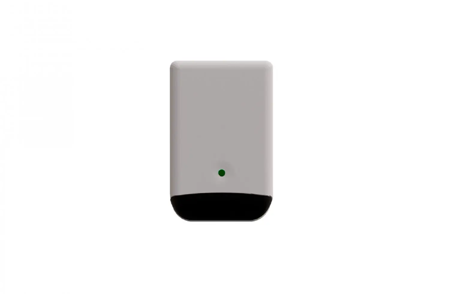
Intesis gateway IN485UNI001I000 provides full integration of infrared-enabled air conditioners into Modbus RTU (EIA-485) networks.
Compatible with most AC units equipped with an IR receiver
Main features
- Reduced dimensions and quick installation
- Compatible with most AC brands, infrared enabled models
- Wall or desktop (surface) mounted. Reduced dimensions for easy installation.
- Direct connection to Modbus RTU over EIA-485 as a slave device
- Up to 63 interfaces can be connected to the Modbus network
- Auto-learn function for quick and easy setup of IR remote control
- Mini USB port for connection to config software. It is also used for power supply
- Power adapter included (EU, UK, USA and AU plugs supplied).
- Simultaneous control of the AC unit both from Modbus and from IR remote controller.
Quick setup
- Connect the interface via mini USB to the PC (cable not included, Mini-USB Type Mini B)
- Configure your device using Intesis MAPS configuration software (Check Intesis MAPS User Manual for detailed description).
- Install the interface in proximity of the AC indoor unit and connect it to the power supply. Check the interface location that best fits the installation (More at chapter 3. Device Installation ). Use parrot mode to verify the device location.
- Connect RS485 to Modbus RTU network.
![]() IMPORTANT: Power supply
IMPORTANT: Power supply
The interface is USB-powered. If not connected to a computer for setting or testing routines from the Config Tool, the USB port should be feeding 5 Volts DC from the power adapter (included)
Device Installation
This Intesis device is equipped with four infrared (IR) emitters and one IR receiver. Two emitters point at the front, two are 45º oriented, downwards, one for each side. The receiver gets feedback from the IR wireless remote controller, so the AC unit status is reported to the Modbus system.
Built-in IR emitters and IR receiver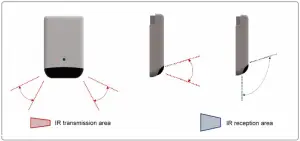
Device emplacement and IR connection
Intesis IN485UNI001I000 is intended for surface mount, either wall or desktop. Different emplacements are acceptable, as shown in figures below.
Wall mount.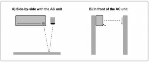
Wall / desktop mount.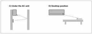
Case A: Placed side-by-side with the AC unit. The signal will travel from the Intesis device to the AC unit taking advantage of the rebounds on the floor or furniture present in the room.
Case B: Placed in front of the AC unit. The signal will travel from the Intesis device directly to the AC unit.
Case C: Below the AC unit. In this case, the signal will travel from the Intesis device to the AC unit taking advantage of the rebounds on the wall in front of it or other furniture.
Case D: Desktop mount. The signal will travel directly from the Intesis device to the AC unit.
Built/in ports and sensors.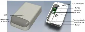
Connection to EIA-485
Notice: the EIA-485 screw terminal block at the back of the device.
Mini USB port
Use the USB cable to connect the device to a computer running config software, for setting and testing purposes, or to the power adapter (included), for regular operation
Modbus Interface Specification
Modbus physical layer
IN485UNI001I000 implements a Modbus RTU Slave interface, to be connected to an EIA-485 bus. It performs an 8N2 communication (8 data bits, no parity and 2 stop bit) with several available baud rates (2400 bps, 4800 bps, 9600 bps – default-, 19200 bps, 38400 bps, 57600 bps, 76800 bps and 115200 bps). It also supports 8N1 communication (8 data bits, no parity and 1 stop bit).
Modbus Registers
All registers are type “16-bit unsigned Holding Register” and they use the standard Modbus big endian notation. the Modbus big endian notation.
AC Control and status registers
IN485UNI001I000 has the following Modbus Maps to control and monitor the AC unit. Consider that this table shows the maximum range of values available in every Modbus register and that it will be adapted to the IR control to simulate in every application.
| Register Address (protocol address) | Register Address (PLC address) | R/W | Description |
| 0 | 1 | R/W | AC unit On/Off
|
| 1 | 2 | R/W | AC unit Mode 1
|
| 2 | 3 | R/W | AC unit Fan Speed 1
|
| 3 | 4 | R/W | AC unit Vertical Vane Position 1
|
| 4 | 5 | R/W | AC unit Temperature Set point 2,3,3
|
| 5 | 6 | R | AC unit Ambient Temperature ¡Error! Marcador no definido.,2,3
|
- Available values will depend on the AC unit mode. Check the AC unit user manual to know the possible values for this register
- Magnitude for this register can be adjusted to Celsius x 1ºC, Celsius x 10ºC (default) or Fahrenheit.
- It is not possible turn to x10 the value shown in Fahrenheit
| Register Address (protocol address) | Register Address (PLC address) | R/W | Description |
| |||
| 7 | 8 | R/W | IN485UNI001I000 Disablement 4
|
| 8 | 9 | R/W | AC Remote Control Disablement 5
|
| 9 | 10 | R/W | AC unit Operation Time
|
| 26 | 27 | R/W | AC unit Horizontal Vane Position ¡Error!Marcadornodefinido.
|
| 27 | 28 | R/W | AC unit Vertical Vane Pulse ¡Error! Marcador no definido.
|
| 34 | 35 | R/W | AC unit Horizontal Vane Pulse ¡Error! Marcador no definido.
|
| 70 | 71 | R | Relative humidity
|
| 21 | 22 | R | Max. number of fan speeds Maximum number of fan speeds available. |
| 24 | 25 | R | AC max set point ¡Error! Marcador no definido.,2,3
|
| 25 | 26 | R | AC min setpoint ¡Error! Marcador no definido.,2,3
|
| 200 | 201 | R/W | Parrot Mode
|
AC startup registers
| Register Address (protocol address) | Register Address (PLC address) | R/W | Description |
| 1100 | 1101 | R/W | Reset operation at startup:
|
| 1101 | 1102 | R/W | AC unit On/Off at startup
|
| 1102 | 1103 | R/W | AC unit Mode at startup 5 |
- This value is stored in non-volatile memory
5 Available values will depend on the AC unit mode. Check the AC unit user manual to know the possible values for this register
| Register Address (protocol address) | Register Address (PLC address) | R/W | Description |
| |||
| 1103 | 1104 | R/W | AC unit Fan Speed at startup 1
|
| 1104 | 1105 | R/W | AC unit Temperature Setpoint at startup 6,7,3
61..86 (ºF) (0 = undetermined) |
| 1105 | 1106 | R/W | AC unit U/D Vane Position at startup ¡Error!Marcadornodefinido.
|
| 1106 | 1107 | R/W | AC unit L/R Vane Position at startup ¡Error!Marcadornodefinido.
|
Device Registers
| Register Address (protocol address) | Register Address (PLC address) | R/W | Description |
| 14 | 15 | R | Modbus RTU baud-rate
|
| 15 | 16 | R | Modbus Slave Address
|
| 49 | 50 | R | Device definition (device ID) |
| 50 | 51 | R | Software version |
| 97 | 98 | R/W | Block Periodic Sending’s 8
|
| |||
| 99 | 100 | R/W | Reset device
|
| 203 | 204 | R | IR Remote version |
| 204 | 205 | R | IR Remote code |
| 202 | 203 | R/W | RGB led criteria:
|
| 206 | 207 | R/W | RGB Led intensity. Values 1…5 |
| 10 | 11 | R | AC unit Alarm Status
|
| 11 | 12 | R | Error Code (IN485UNI001I000 errors)
Error value Error MBS Description 0 65536 No error -4 65532 Initialization value -15 65521 Internal error -16 65520 RCF Wrong CRC error |
Magnitude for this register can be adjusted to Celsius x 1ºC, Celsius x 10ºC (default) or Fahrenheit. It is not possible turn to x10 the value shown in Fahrenheit. If the register is configured as “0:Non-blocked”, all commands received from Modbus will be sent to the AC system. If “1: Blocked”, commands from Modbus will only be sent to the AC system if they differ from the previous value.
Implemented Modbus functions
IN485UNI001I000 implements the following standard Modbus functions:
- 3: Read Holding Registers
- 4: Read Input Registers
- 6: Write Single Register
- 16: Write Multiple Registers (Despite this function is allowed, the interface does not allow to write operations on more than 1 register with the same request, this means that length field should be always be 1 when this function is being used in case of writing)
EIA-485 bus. Termination resistors and Fail-Safe Biasing mechanism
EIA-485 bus requires a 120 Ω terminator resistor at each end of the bus to avoid signal reflections.
In order to prevent fail status detections by bus receivers when all the transmitters’ outputs are in three-state (high impedance), it is also required a fail-safe biasing mechanism. This mechanism provides a safe status (a correct voltage level) in the bus when all the transmitters’ outputs are in three-state. The Fail-Safe-Biasing mechanism is enabled by DIP-switch settings
Please check section 5.1 DIP-switch settings for details
The IN485UNI001I000 device includes an on-board terminator resistor of 120 Ω that can be connected to the EIA-485 bus by using built-in DIP-switch block. Some Modbus RTU EIA-485 Master devices can provide also internal 120 Ω terminator resistor and/or fail-safe biasing. Check the technical documentation of the Master devices connected to the EIA-485 network in each case.
Configuration settings
DIP-switch settings
To access the on boarded DIP-switch block, the enclosure must be opened by bending both frontal tabs (inserting a plane tool tip size <5 mm). This operation must be performed by qualified personnel only.
On boarded DIP-switch block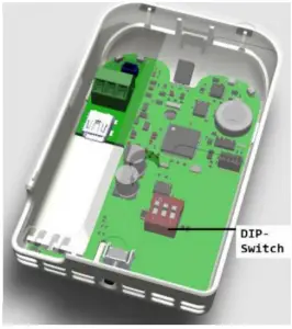
| DIP-switch | Description |
 | EIA-485 bus without a termination resistor |
 | Internal 120 Ω termination resistor connected to EIA-485 bus |
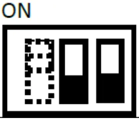 | No bus polarization |
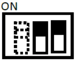 | Active bus polarization |
The device is equipped with one push button which performs two different actions:
Action 1: AC ON&OFF
| AC ON/OFF STATUS | User action | Device action |
| OFF | 1 click | ON+COOL+25ºC |
| OFF | 2 clicks | ON+HEAT+21ºC |
| ON | 1 or 2 clicks | OFF |
When Parrot mode is active, switching ON&OFF the AC is not permitted from this button. Please, exit Parrot mode to enable AC ON&OFF.
Action 2: Parrot mode enable / disable
| AC ON/OFF STATUS | User action | Device action |
| ON or OFF | 3 clicks | Activate/deactivate Parrot mode |
When Parrot mode is enabled, the device will simply emit every IR signal picked at by the receiver, acting as a repeater. Parrot mode is used for testing or troubleshooting to confirm the device location for AC control.
Device LED indicator
The device is equipped with one multicolor LED indicator. Different colors are used to report different operation modes and operation conditions, as described in following tables
Normal operation
| LED COLOR | Blink freq / steady | Device informs… |
| READ | STEADY | HEAT mode |
| BLUE | STEADY | COOL mode |
| BLUE | STEADY | DRY mode |
| YELLOW | STEADY | AUTO mode |
| GREEN | STEADY | FAN mode |
| RED | BLINK 3 times | Command received or sent during HEAT mode |
| BLUE | BLINK 3 times | Command received or sent during COOL mode |
| BLUE | BLINK 3 times | Command received or sent during DRY mode |
| YELLOW | BLINK 3 times | Command received or sent during AUTO mode |
| GREEN | BLINK 3 times | Command received or sent during FAN mode |
Parrot mode
Parrot mode is a function to find the best device location for its normal operation
| LED COLOR | Blink freq / steady | Device informs… |
| WHITE | 0.5 s ON – 0.5 s OFF | Parrot mode ON |
Auto-learn mode
Auto learn is a function that allows to auto configure the native AC infrared remote controller in the IN485UNI001I000 device. This function can be enabled via Intesis Maps only, please, refer to Intesis Maps configuration manual for IN485UNI001I000 to use this function.
| LED COLOR | Blink freq / steady | Device informs… |
| WHITE | STEADY | Device is ready to get an IR frame |
Device connected via USB
| LED COLOR | Blink freq / steady | Device informs… |
| ORANGE | STEADY (low intensity) | USB link performed |
| ORANGE | STEADY (high intensity) | Intesis Maps communication |
| MAGENTA | 0.5 s ON – 0.5 s OFF | USB communication (FW download in progress) |
| CYAN | 1s ON – 1s OFF (x3) | FW download finished |
Error notification
| LED COLOR | Blink freq / steady | Device informs… |
| RED | Deadly blinking | RCF corruption |
Check Intesis Maps configuration manual to know how to overcome this error
Intesis® MAPS Config Tool
This interface in configured using Intesis Maps®. You can download this software for free in www.intesis.com. Please, review Intesis Maps IN485UNI001I000 user manual to learn how to configure the device using this software
Technical Specs
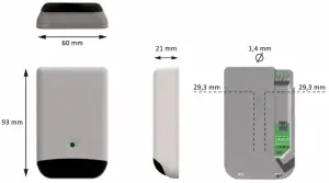
| Enclosure | Plastic, type PC (UL 94 V-0) Dimensions: 93 x 60 x 21 mm / 3.7” x 2.3” x 0.8” Color: Light Grey. NCS S 1002-B | Operation Temp | 0°C to +60°C |
| Weight | 55 g | Storage Temp | -20°C to +85°C |
| Mounting | Surface mount (wall or desktop). | Operation humidity | 5% to 95%, non-condensing |
| Terminal Wiring (low-voltage signals) | Per terminal: solid wires or stranded wires (twisted or with shielded termination) 1 core: 0.25mm2… 1 mm2 2 cores: 0.25mm2… 0.75 mm2 3 cores: 0.25mm2… 0.75 mm2 | Storage Temp | < 95%, non-condensing |
| EIA – 485 | 1 x EIA485 3-pin plug-in screw terminal block: A, B, SG | Protection | IP20 (IEC60529) |
| USB port | 1 x Mini-USB Type Mini B. Power consumption: max. 400mA @ 5 Vdc | LED indicator | 1 x external LED – operational status |
| Buttons | 1 x Button | ||
Dimensions
List of compatible AC indoor units.
This interface is compatible with almost every AC indoor unit with IR (infrared) control. Check if your AC unit is already integrated in this link.
If your AC unit or IR remote controller were not in the list, contact Intesis TS Team to confirm if the IR remote is already integrated or how to initiate the integration process.


