
Intesis INMBSLGE001R000 Modbus RTU Interface For LG Air Conditioners
Important User Information
Disclaimer The information in this document is for informational purposes only. Please inform HMS Industrial Networks of any inaccuracies or omissions found in this document. HMS Industrial Networks disclaims any responsibility or liability for any errors that may appear in this document. HMS Industrial Networks reserves the right to modify its products in line with its policy of continuous product development. The information in this document shall therefore not be construed as a commitment on the part of HMS Industrial Networks and is subject to change without notice. HMS Industrial Networks makes no commitment to update or keep current the information in this document. The data, examples and illustrations found in this document are included for illustrative purposes and are only intended to help improve understanding of the functionality and handling of the product. In view of the wide range of possible applications of the product, and because of the many variables and requirements associated with any particular implementation, HMS Industrial Networks cannot assume responsibility or liability for actual use based on the data, examples or illustrations included in this document nor for any damages incurred during installation of the product. Those responsible for the use of the product must acquire sufficient knowledge in order to ensure that the product is used correctly in their specific application and that the application meets all performance and safety requirements including any applicable laws, regulations, codes and standards. Further, HMS Industrial Networks will under no circumstances assume liability or responsibility for any problems that may arise as a result from the use of undocumented features or functional side effects found outside the documented scope of the product. The effects caused by any direct or indirect use of such aspects of the product are undefined and may include e.g. compatibility issues and stability issues.
Presentation
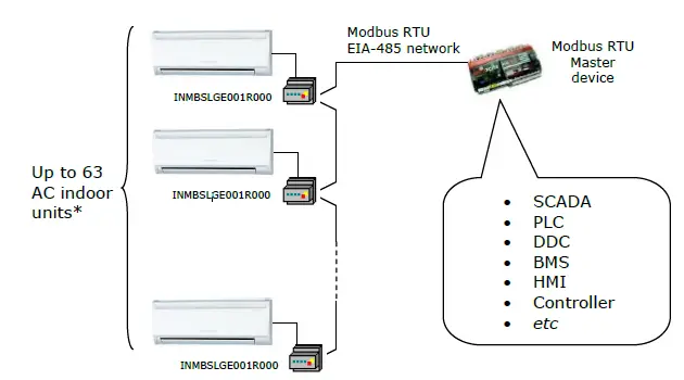
The INMBSLGE001R000 interfaces allow a complete and natural integration of LG air conditioners into Modbus RTU (EIA-485) networks. Reduced dimensions. 93 x 53 x 58 mm 3.7” x 2.1” x 2.3” Quick and easy installation. Mountable on DIN rail, wall, or even inside the indoor unit of AC.
- External power not required.
- Direct connection to Modbus RTU (EIA-485) networks. Up to 63 INMBSLGE001R000 devices can be connected in the same network.
INMBSLGE001R000 is a Modbus slave device. - Direct connection to the AC indoor unit.
- Configuration from both on-board DIP-switches and Modbus RTU.
- Total Control and Supervision.
- Real states of the AC unit’s internal variables.
- Allows simultaneous use of the AC’s remote controls and Modbus RTU.

Connection
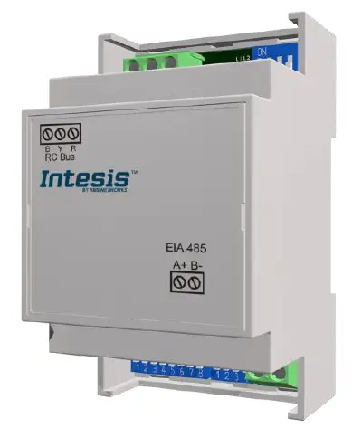
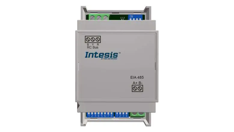
The interface comes with a plug-in terminal block of 3 poles to establish direct connection with the AC indoor unit. It comes as well with a plug-in terminal block of 2 poles to establish direct connection with the Modbus RTU EIA-485 network.
Connect to the AC indoor unit
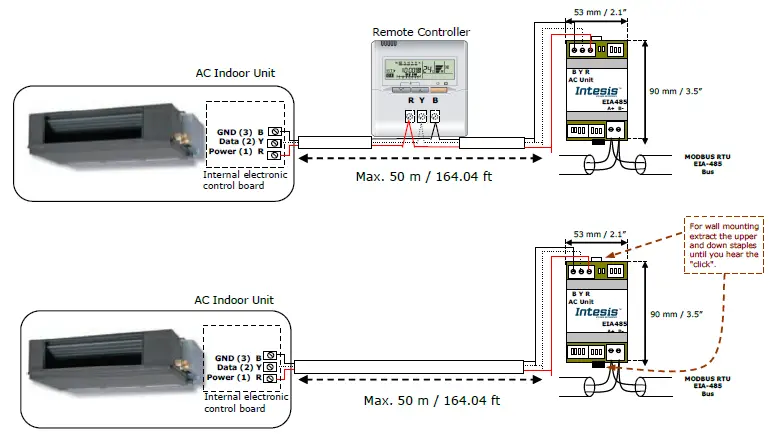
The INMBSLGE001R000 connects directly to the LG BYR Bus, which is not provided within the interface. Depending on which controllers are available, the recommended connection’ methods are the following ones (details in Figure 2. 1):
- Wired remote control available. Connect the gateway as Slave in parallel with the wired Remote Controllers (Controller acts as Master).
- No remote control available Connect the gateway directly to the BYR bus of the indoor unit as Master when there is no LG Remote Controller.
Maximum BYR bus length is 50 m / 164.04 ft. The bus has no polarity sensitivity.
Important: If a wired remote controller of the AC manufacturer is connected in the same bus, communication may shut down.
Attention: Type A units don’t allow to install a Remote Controller and INMBSLGE001R000 together.
Connection to the EIA-485 bus
Connect the EIA-485 bus wires to the plug-in terminal block (the one of two poles) of INMBSLGE001R000 and keep the polarity on this connection (A+ and B-). Make sure that the maximum distance to the bus is 1,200 meters (3,937 ft). Loop or star typologies are not allowed in the case of the EIA-485 bus. A terminator resistor of 120Ω must be present at each end of the bus to avoid signal reflections. The bus needs a fail-safe biasing mechanism (see section 4.6 for more details).
Quick Start Guide
- Disconnect the air conditioning from the Mains Power.
- Attach the interface next to the AC indoor unit (wall mounting) following the instructions of the diagram below or install it inside the AC indoor unit (respect the safety instructions given).
- Connect the BYR bus between the interface and the AC indoor unit following the instructions of the diagram. Screw each bare cable end in the corresponding BYR terminals of each device.
- Connect the EIA-485 bus to the connector EIA485 of the interface.
- Close the AC indoor unit.
- Check the DIP-Switch configuration of the Intesis interface and make sure it matches the current installation’s parameters.
By default, the interface is set to:
- Modbus Slave Address ➔ 1
- Modbus baud rate ➔ 9600 bps
- These parameters can be modified from SW4 and SW3 DIP-Switches.
- All other switch positions are set at low level (Off position
NOTE: All changes on the DIP-Switch configuration require a system power cycle to be applied.
- Connect the AC system to Mains Power.
IMPORTANT: The Intesis interface requires to be connected to the AC unit (powered) to start communicating.
Modbus Interface Specification
Modbus physical layer INMBSLGE001R000 implements a Modbus RTU (Slave) interface, to be connected to an EIA-485 line. It performs 8N2 communication (8 data bits, no parity and 2 stop bit) with several available baud rates (2400 bps, 4800 bps, 9600 bps -default-, 19200 bps, 38400 bps, 57600 bps, 76800 bps and 115200 bps). It also supports 8N1 communication (8 data bits, no parity and 1 stop bit).
Modbus Registers All registers are type “16-bit unsigned Holding Register” and they use the Modbus big endian notation.
| Register Address (protocol address) | Register Address (PLC address) | R/W | Description |
| 0 | 1 | R/W | AC unit On/Off § 0: Off § 1: On |
|
1 |
2 |
R/W | AC unit Mode 1 § 0: Auto § 1: Heat § 2: Dry § 3: Fan § 4: Cool |
| 2 | 3 | R/W | AC unit Fan Speed 1 § 0: Auto § 1..7: Pos. 1 .. Pos. 7 |
| 3 | 4 | R/W | AC unit Vane Position 1 § 0: No Swing § 1..4: Pos. 1 .. Pos. 4 § 10: Swing § 11: Swirl |
| 4 | 5 | R/W | AC unit Temperature Setpoint 1,2,3 § -32768 (Initialization value) § 16..30ºC (ºC/x10ºC) § 61..86ºF |
| 5 | 6 | R | AC unit Temperature reference 1,2,3 § -32768 (Initialization value) § 10..38ºC (ºC/x10ºC) § 50..100ºF |
| 6 | 7 | R/W | Window Contact § 0: Closed (Default) § 1: Open |
If the register is configured as “0:Non-blocked”, all commands received from Modbus will be sent to the AC system. If “1: Blocked”, commands from Modbus will only be sent to the AC system if they differ from the previous value.
This register applies to firmware version 1.7 onwards Once window contact is open, a count-down to switch off the AC Unit will start from this configured value.
Considerations on Temperature Registers
- AC unit temperature setpoint (R/W) (register 4 – in Protocol address / register 5 – in PLC address):
This is the adjustable temperature setpoint value that must be required by the user. This register can be read (Modbus function 3 or 4) or written (Modbus functions 6 or 16). A remote controller connected to the LG indoor unit will report the same temperature setpoint value as this register but only will happen when no AC unit´s external reference is provided from INMBSLGE001R000 (see detail for register 22/23 below). - AC unit temperature reference (R) (register 5 – in Protocol address/register 6 – in PLC address):
This register reports the temperature that is currently used by the LG indoor unit as the reference of its own control loop. Depending on the configuration of the indoor unit, this value can be the temperature reported by the sensor on the return path of the LG indoor unit or the sensor of its remote controller. It is a read-only register (Modbus functions 3 or 4). - AC unit external temperature reference (Modbus) (R/W) (register 22 – in Protocol address / register 23 – in PLC address):
This register allows us to provide an external temperature sensor from the Modbus side. LG indoor unit does not allow on devices like INMBSLGE001R000 to provide directly temperature to be used as a reference of the control loop of the AC indoor unit. In order to overcome this limitation and enable the usage of an external temperature sensor (i.e.from Modbus side), INMBSLGE001R000 applies the following mechanism (only if “external temperature’s reference” is being used):- After a couple of values have been entered in the “AC unit external temperature’s reference” (register 22/23) and “AC unit temperature set point” (register 4/5), INMBSLGE001R000 is going to estimate the temperature chosen implied (e.g. if a “temperature setpoint (register 4/5)” of 22ºC, and an “external temperature reference (register 22/23)” of 20ºC are entered, INMBSLGE001R000 will assume that the user is demanding a +2ºC increase in temperature).
- By knowing at any time the ambient temperature currently used by the indoor unit to control its own operation (register 5/6), INMBSLGE001R000 can calculate the required temperature setpoint needed to apply the decrease/increase on the real temperature and reach the temperature chosen by the user (following the example above, if INMBSLGE001R000 reads an “ambient temperature” (register 5/6) of 24ºC in the indoor unit, it will apply a final setpoint of 24ºC + 2ºC = 26ºC).
- At this moment, each time that INMBSLGE001R000 detects a change on the ambient temperature reported by the indoor unit (register 5/6), it will also change the required setpoint, in order to keep the temperature required by the user at any time. If we follow the last example, if INMBSLGE001R000 receives a new temperature´s value coming from the indoor unit of 25ºC, INMBSLGE001R000 will automatically adjust the temperature setpoint required of the AC indoor unit to 25ºC + 2ºC = 27ºC).
- In general, INMBSLGE001R000 is constantly applying the “Virtual Temperature” formula:
Where:- SAC – setpoint value currently applied to the indoor unit
- Su – setpoint value written at Modbus side (register 4/5)
- Tu – external temperature reference written at Modbus side (register 22/23) TAC – ambient temperature that the indoor unit is using as the reference of its own control loop (register 5/6) When INMBSLGE001R000 detects a change in any of the values of
{ Su , Tu , TAC }, it will send the new setpoint (SAC) to the indoor unit. After the startup, the value for “external temperature’s reference” (register 22/23) has a value -32768 (0x8000). This value means that no external temperature reference is being provided through INMBSLGE001R000. In this scenario, the setpoint value shown in register 4/5 will always be the same as the current setpoint value of the indoor unit. AC indoor unit will use its own return path temperature sensor as reference for its control loop.
- When the mechanism of “Virtual Temperature” is applied. The temperature setpoint’s value shown by the Remote Controller or other Control System from LG connected to the indoor unit may show a different value from the value shown in register 4/5.
- If it is desired to use the temperature’s reading from the Remote Control as the reference temperature for the Indoor Unit (TAC), the Remote Controller must be configured as Master, and the LG AC indoor unit must have the option “thermostat sensor in the Remote Controller” activated. This configuration is done via a LG Remote Controller connected to the indoor unit and must be done by LG authorized installers while the AC is being installed.
- When INMBSLGE001R000 is set as “Master” of the BYR bus and the LG AC Indoor unit has the option “thermostat sensor in the Remote Controller” activated. The external temperature’s sensor connected to Modbus RTU EIA-485 network provides directly the value currently applied to the indoor unit ( SAC ), and the process of the Virtual temperature is not applied. In this case, the Remote Controller or any other Control System connected from LG is not able to send the external temperature reference’s value to the register 22/23.
- AC Real Setpoint temperature (R) (register 23 – In Protocol address / register 24 – in PLC address): As it has been detailed on the previous point, the real temperature setpoint in the indoor unit and the temperature setpoint requested from INMBSLGE001R000 might differ (when a value in register 22/23 – “external temperature reference” is entered). This register always informs about the current temperature setpoint which is being used by the indoor unit – it is also includes the temperature setpoint that will be shown by an additional remote controller from LG connected to the indoor unit, if it is present on the system.
Moreover, notice that temperature values of all these four registers are expressed according to the temperature´s format configured through its onboard DIP-Switches (See “4.3 – DIP-switch Configuration Interface”). These following formats are possible: - Celsius value: The value in Modbus register is the temperature value in Celsius (i.e. a value “22” in the Modbus register must be interpreted as 22ºC).
- Decicelsius value: The value in Modbus register is the temperature value in decicelsius (i.e. a value “220” in the Modbus register must be interpreted as 22.0ºC).
- Fahrenheit value: The value in Modbus register is the temperature value in Fahrenheit (i.e. a value “72” in the Modbus register must be interpreted as 72ºF (~22ºC).
DIP-switch Configuration Interface
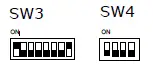
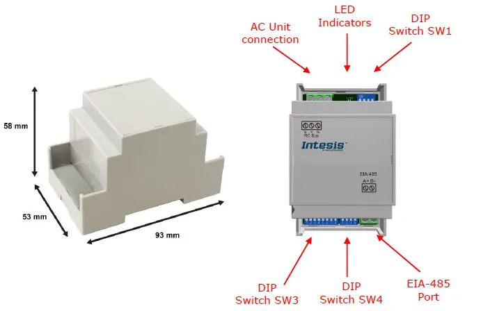
All the configuration values on INMBSLGE001R000 can be written and read from Modbus interface. Otherwise, some of them can also be setup from its on-board DIP-switch interface. The device has DIP-switches SW1, SW3 and SW4 on the following locations: 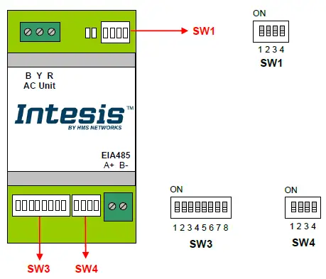
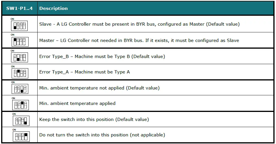
The following tables apply to the interface´s configuration through DIP-switches: SW1 – AC indoor unit’s features
SW3/SW4 – Baud rate configuration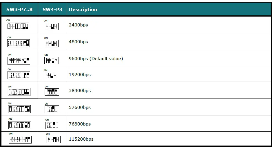
SW4 – Degrees/Decidegrees (x10), temperature magnitude (ºC/ºF) and EIA-485 termination resistor.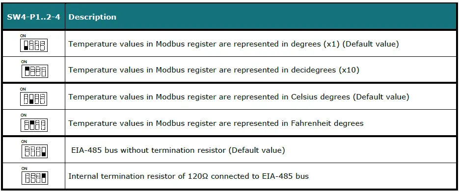
SW3 – Modbus Slave address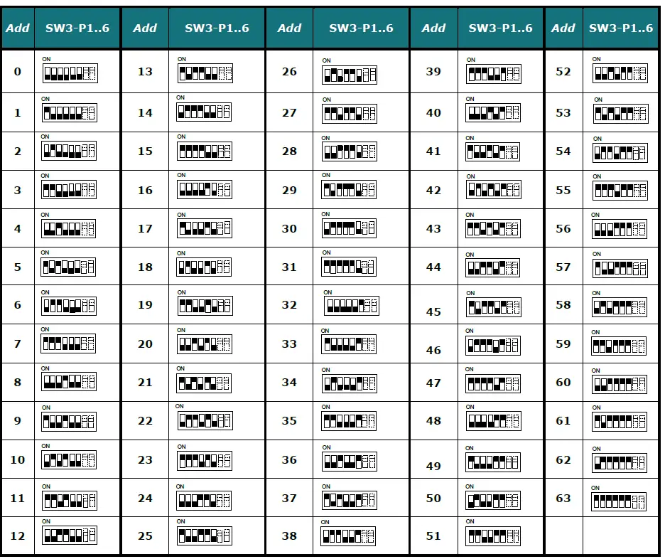
Implemented Functions
INMBSLGE001R000 implements the following standard Modbus functions:
- 3: Read Holding Registers
- 4: Read Input Registers
- 6: Write Single Register
- 16: Write Multiple Registers (Despite this function is allowed, the interface does not allow to write operations on more than 1 register with the same request, this means that length field should be always be 1 when this function is being used in case of writing)
Device LED indicator
The device includes two LED indicators to show all the possible operational states. In the following table there are written the indicators which can be performed and their meaning.
L1 (green LED)
| Device status | LED indication | ON / OFF Period | Description |
| During not normal operation | LED blinking | 500ms ON / 500ms OFF | Communication error |
| During normal operation | LED flashing | 100ms ON / 1900ms OFF | Normal operation (configured and working properly) |
L2 (red LED)
| Device status | LED indication | ON / OFF Period | Description |
| During not normal operation | LED Pulse | 3sec ON / — OFF | Under voltage |
L1 (green LED) & L2 (red LED)
| Device status | LED indication | ON / OFF Period | Description |
| During normal operation | LED Pulse | 5sec ON / — OFF | Device Start-up |
| During not normal operation | LED alternatively blinking | 500ms ON / 500ms OFF | Flash checksum not OK |
EIA-485 bus. Termination resistors and Fail-Safe Biasing mechanism EIA-485 bus require a 120Ω terminator resistor at each end of the bus to avoid signal reflections. EIA-485 bus requires a 120Ω terminator resistor at each end of the bus to avoid signal reflections. In order to prevent fail status detected by the receivers, which are “listening to” the bus, when all the transmitters’ outputs are in three-state (high impedance), it is also required a fail-safe biasing mechanism. This mechanism provides a safe status (a correct voltage level) in the bus when all the transmitters’ outputs are in three-state. This mechanism must be supplied by the Modbus Master. The INMBSLGE001R000 device includes an onboard terminator resistor of 120Ω that can be connected to the EIA-485 bus by using DIP-switch SW4. Some Modbus RTU EIA-485 Master devices can provide also an internal 120Ω terminator resistor and/or fail-safe biasing mechanism (Check the technical documentation of the Master device connected to the EIA-485 network in each case).
Mechanical and electrical features
| Enclosure | Plastic, type PC (UL 94 V-0) Net dimensions (dxwxh): 93 x 53 x 58 mm / 3.7” x 2.1” x 2.3” Color: Light Grey. RAL 7035 | Operation Temperature | 0ºC to +60ºC |
| Weight | 85 g. | Stock Temperature | -20ºC to +85ºC |
| Mounting | Wall DIN rail EN60715 TH35. | Operational Humidity | <95% RH, non-condensing |
| Terminal Wiring (for low-voltage signals) | For terminal: solid wires or stranded wires (twisted or with ferrule) 1 core: 0.5mm2… 2.5mm2 2 cores: 0.5mm2… 1.5mm2 3 cores: not permitted |
Stock Humidity |
<95% RH, non-condensing |
| Modbus RTU port | 1 x Serial EIA485 Plug-in screw terminal block (2 poles): A, B Compatible with Modbus RTU EIA-485 networks | Isolation voltage | 1500 VDC |
| AC unit port | 1 x BYR bus Plug-in screw terminal block (3 poles): B, Y, R Compatible with LG networks | Isolation resistance | 1000 MΩ |
| Switch 1 (SW1) | 1 x DIP-Switch for AC features | Protection | IP20 (IEC60529) |
| Switch 3 (SW3) | 1 x DIP-Switch for Modbus RTU settings | LED indicators | 2 x Onboard LED – Operational status |
| Switch 4 (SW4) | 1 x DIP-Switch for extra functions | ||
List of supported AC Unit Types.
A list of LG indoor unit model references compatible with INMBSLGE001R000 and its available features can be found on this link: https://www.intesis.com/docs/compatibilities/inxxxlge001r000_compatibility
Error Codes
| Error Code Modbus | Remote Controller Error | Error description |
| 0 | N/A | No active error |
| 1 | 1 | Room air sensor fault |
| 2 | 2 | Indoor unit pipe in sensor fault |
| 3 | 3 | Communication fault between wired remote controller and indoor unit |
| 4 | 4 | Drain pump fault |
| 5 | 5 | Communication fault between indoor unit and outdoor unit |
| 6 | 6 | Indoor unit pipe out sensor fault |
| 7 | 7 | Indoor unit mode runs on opposite to outdoor unit |
| 8 | 8 | N/A |
| 9 | 9 | EEPROM memory fault |
| 10 | 10 | BLDC motor signal fault or motor lock |
| 11 | 11 | HEX middle point sensor fault |
| 12 | 12 | heater terminal block sensor fault |
| 13 | 13 | N/A |
| 14 | 14 | N/A |
| 15 | 15 | N/A |
| 16 | 16 | N/A |
| 17 | 17 | Outlet air sensor fault |
| 18 | 18 | Return air sensor fault |
| 19 | 19 | No communication response from sub PCB to main PCB |
| 20 | 20 | No communication response from main PCB to sub PCB |
| 21 | 21 | IPM fault |
| 22 | 22 | AC input is over current (RMS) |
| 23 | 23 | DC link low or high voltage |
| 24 | 24 | High pressure or low pressure switch on |
| 25 | 25 | High/low input voltage |
| 26 | 26 | Compressor start failure |
| 27 | 27 | PSC/PFC fault |
| 28 | 28 | DC link high voltage |
| 29 | 29 | Overcurrent at compressor input |
| 32 | 32 | Discharge temperature is high at inverter compressor |
| 33 | 33 | Discharge temperature is high at constant speed compressor |
| 34 | 34 | High pressure is too high |
| 35 | 35 | Low pressure is too low |
| 36 | 36 | Compression ratio is too low |
| 39 | 39 | Communication fault between PFC and inverter PCB |
| 40 | 40 | CT sensor fault |
| 41 | 41 | Discharge sensor at inverter compressor is fault |
| 42 | 42 | Low pressure sensor is fault |
| 43 | 43 | High pressure sensor is fault |
| 44 | 44 | Air sensor at outdoor unit is fault |
| 45 | 45 | HEX sensor at outdoor unit is fault |
| 46 | 46 | Compressor suction sensor is fault |
| 47 | 47 | Discharge sensor at constant speed compressor is fault |
| 48 | 48 | HEX outlet sensor at outdoor unit is fault |
| 49 | 49 | IPM temperature sensor is fault |
| 50 | 50 | Missing phase among 3 phase |
| 51 | 51 | Over combination ratio |
| 52 | 52 | No communication from inverter PCB detected at main PCB |
| 53 | 53 | Communication fault between indoor and outdoor unit |
| 54 | 54 | Reverse phase is detected |
| 57 | 57 | No communication from main PCB detected at inverter PCB |
| 59 | 59 | Wrong outdoor unit combination |
| 60 | 60 | Inverter EEPROM memory fault |
| 61 | 61 | Outdoor pipe temperature is too high |
| 62 | 62 | IPM temperature is too high |
| 65 | 65 | IPM temperature sensor is fault |
| 67 | 67 | Fan locked or fan start failure |
| 69 | 69 | CT sensor of constant speed compressor 1 is fault |
| 70 | 70 | CT sensor of constant speed compressor 2 is fault |
| 71 | 71 | PFC CT sensor fault |
| 72 | 72 | Function error of outdoor 4way valve (reversing valve) |
| 73 | 73 | DC peak current is over |
| 74 | 74 | Unbalance at 3 phase |
| 75 | 75 | Fan CT sensor fault |
| 76 | 76 | Fan DC link voltage is high |
| 77 | 77 | Fan input voltage is high |
| 78 | 78 | Fan hall sensor fault |
| 79 | 79 | Fan motor start failure |
| 86 | 86 | Main PCB EEPROM is fault |
| 87 | 87 | Fan PCB EEPROM is fault |
| 88 | 88 | PFC PCB EEPROM is fault |
| 90 | 90 | Inlet temperature sensor of external PCB is fault |
| 91 | 91 | Outlet temperature sensor of external PCB is fault |
| 104 | 104 | No Communication from slave is detected |
| 105 | 105 | Communication fault between fan and inverter PCB |
| 106 | 106 | Fan PCB IOM fault |
| 107 | 107 | Fan DC link voltage is low |
| 113 | 113 | Liquid pipe sensor fault |
| 114 | 114 | Sub-cooling inlet pipe sensor fault |
| 115 | 115 | Sub-cooling outlet pipe sensor fault |
| 116 | 116 | Oil level sensor fault |
| 145 | 145 | No communication from external PCB is detected at main PCB |
| 151 | 151 | 4 way valve failure |
| 153 | 153 | Upper HEX sensor fault |
| 154 | 154 | Bottom HEX sensor fault |
| 173 | 173 | Over / low current at constant speed compressor 1 |
| 174 | 174 | Over / low current at constant speed compressor 2 |
| 182 | 182 | Communication fault between main and sub micom in external PCB |
| 187 | 187 | Hydro-kit water temperature sensor fault |
| 190 | 190 | Inverter PCB heat sink temperature is high |
| 191 | 191 | Inverter PCB heat sink temperature sensor fault |
| 193 | 193 | Fan PCB heat sink temperature is high |
| 194 | 194 | Fan PCB heat sink temperature sensor fault |
| 200 | 200 | Auto piping failure |
| 201 | 201 | Fault at liquid pipe sensor of Heat Recovery (HR) unit |
| 202 | 202 | Fault at sub-cooling inlet pipe sensor of Heat Recovery (HR) unit |
| 203 | 203 | Fault at sub-cooling outlet pipe sensor of Heat Recovery (HR) unit |
| 204 | 204 | No communication from outdoor unit is detected at the Heat Recovery (HR) unit |
| 205 | 205 | HR unit addresses are duplicated |
| 237 | 237 | No response from outdoor unit modem at indoor unit modem |
| 238 | 238 | No response from outdoor unit at outdoor unit modem |
| 65535 (-1) | N/A | Error in the communication of INMBSLGE001R000 or Remote Controller with the AC unit. |


