LG Multi Air Conditioner User Manual

CAUTION
Before Servicing the unit, read the safety precautions in General SVC manual. Only for authorized service personnel. Any reproduction, duplication, distribution (including by way of email, facsimile or other electronic means), publication, modification, copying or transmission of this Service Manual is STRICTLY PROHIBITED unless you have obtained the prior written consent of the LG Electronics entity from which you received this Service Manual. The material covered by this prohibition includes, without limitation, any text, graphics or logos in this Service Manual. Copyright © 2019 LG Electronics Inc. All rights reserved. Only training and service purposes.
1. Specification
Indoor
| Model Name | AMNW24GM1A0 [LHN248HV] | AMNW36GM2A0 [LHN368HV] | ||||
| Power Supply | V, Ø, Hz | 208/230, 1, 60 | 208/230, 1, 60 | |||
| Capacity | Btu/h class | 24 000 | 36 000 | |||
| Dimensions | Body | W x H x D | mm | 900 x 270 x 700 | 1 250 x 270 x 700 | |
| W x H x D | inch | 35-7/16 x 10-5/8 x 27-9/16 | 49-3/16 x 10-5/8 x 27-9/16 | |||
| Net Weight | Body | kg (lbs) | 26.6 (58.6) | 38.7 (85.3) | ||
| Heat Exchanger | (Row x Column x Fins per inch) x No. | – | (3 x 13 x 18) x 1 | (3 x 13 x 18) x 1 | ||
| Face Area | m2 (ft2) | 0.21 (2.25) | 0.26 (2.82) | |||
|
Fan | Type | – | Sirocco Fan | Sirocco Fan | ||
| Air Flow Rate | High-static Mode (Factory Set) | H / M / L | m3/min | 22.0 / 20.0 / 18.0 | 32.0 / 28.0 / 24.0 | |
| H / M / L | ft3/min | 777 / 706 / 636 | 1 130 / 989 / 848 | |||
| External Static Pressure | Pa (mmAq) | 58.8 (6) | 58.8 (6) | |||
| Fan Motor | Type | – | BLDC | BLDC | ||
| Output | W x No. | 136.5 x 1 | 350 x 1 | |||
| Sound Pressure Level | H / M / L | dB(A) | 37 / 35 / 34 | 44 / 42 / 40 | ||
| Piping Connections | Liquid | mm(inch) | Φ 9.52 (3/8) | Φ 9.52 (3/8) | ||
| Gas | mm(inch) | Φ 15.88 (5/8) | Φ 15.88 (5/8) | |||
| Drain (O.D. / I.D.) | mm(inch) | Φ 32.0(1-1/4) / 26.0(1-1/32) | Φ 32.0(1-1/4) / 26.0(1-1/32) | |||
| Safety Devices | – | Fuse | Fuse | |||
| Power and Communication Cable (included Earth) | No. x mm2 (AWG) | 4C x 0.75 (18) | 4C x 0.75 (18) | |||
Note:
- Wiring cable size must comply with the applicable local and national code.
- Due to our policy of innovation some specifications may be changed without notification.
- Sound Level Values are measured at Anechoic chamber. Therefore, these values can be increased(maximum 3dB(A)) owing to ambient conditions during operation.
| Conversion Formula | |
| kW = Btu/h x 0.0002931 cfm = CMM x 35.3 |
2. Function Table
| Category | Functions | AMNW24GM1A0 / AMNW36GM2A0 |
|
Air flow | Air supply outlet | 1 |
| Airflow direction control (left & right) | X | |
| Airflow direction control (up & down) | X | |
| Auto swing (left & right) | X | |
| Auto swing (up & down) | X | |
| Airflow steps (fan/cool/heat) | 3 / 3 / 3 | |
| Chaos wind(auto wind) | X | |
| Jet cool/heat | X / X | |
| Swirl wind* | X | |
| Air purifying | Triple filter | X |
| Plasma air purifier | X | |
| Allergy Safe filter | X | |
| Long-life prefilter (washable / anti-fungus) | O | |
| Installation | Drain pump | O |
| E.S.P. control* | O | |
| Electric heater | X | |
| High ceiling operation* | X | |
| Reliability | Hot start | O |
| Self diagnosis | O | |
|
Convenience | Auto changeover** | O (Single Only) |
| Auto cleaning | X | |
| Auto operation(artificial intelligence)** | O (Multi Only) | |
| Auto Restart | O | |
| Child lock* | O | |
| Forced operation | X | |
| Group control* | O | |
| Sleep mode | O | |
| Timer(on/off) | O | |
| Timer(weekly)* | O | |
| Two thermistor control* | O | |
| Auto Elevation Grille* | X | |
| Network Solution(LGAP) | O | |
Notes:
- O : Applied, X : Not applied Accessory model name : Installed at field, ordered and purchased separately by the corresponding model name, supplied with separate package.
- * : These functions need to connect the wired remote controller.
- ** :Auto Changeover function, Telecom shelter controller can be operated when connected with Single A. Auto Operation function can be operated whne connected with Mutli F/FDX.
- For synchro operation, some functions and accessories are not available. Check the outdoor unit’s PDB.
3. Piping Diagrams
Model : AMNW24GM1A0 [LHN248HV]
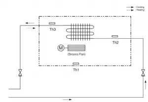
| c | Description | PCB Connector |
| Th1 | Thermistor for Indoor air temperature | CN_ROOM |
| Th2 | Thermistor for Evaporator in temperature | CN_PIPE_IN |
| Th3 | Thermistor for Evaporator out temperature | CN_PIPE_OUT |
Model : AMNW36GM2A0 [LHN368HV]
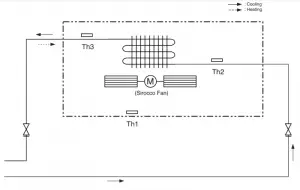
| LOC. | Description | PCB Connector |
| Th1 | Thermistor for Indoor air temperature | CN_ROOM |
| Th2 | Thermistor for Evaporator in temperature | CN_PIPE_IN |
| Th3 | Thermistor for Evaporator out temperature | CN_PIPE_OUT |
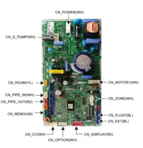
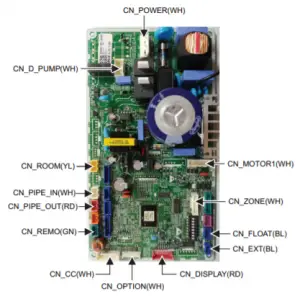
4. Wiring Diagrams
M1, M2 Chassis
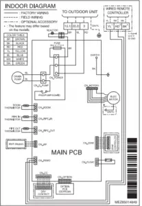
M1 Chassis M2 Chassis
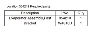
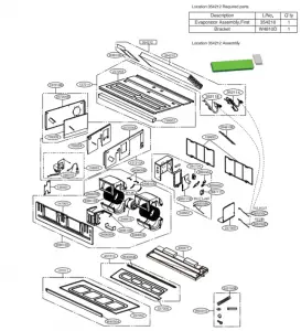
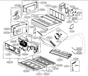
5.exploded view
M1 Chassis
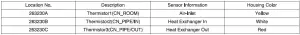
Location No. Description Sensor Information Housing Color
263230A Thermistor1 (CN_ROOM) Air-Inlet Yellow
2632308 Thermistor2(CN_PIPE/IN) Heat Exchanger In White
263230C Thermistor3(CN_PIPE/OUT) Heat Exchanger Out Red
M2 Chassis