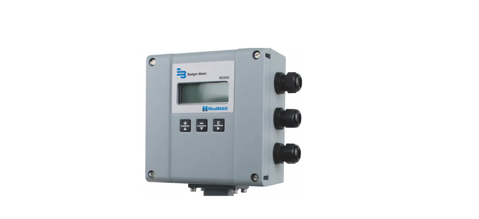
ModMAG M2000 Modbus RTU Communication Daughterboard
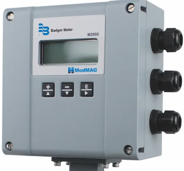
OVERVIEW
The Modbus RTU Communication daughterboard expands the connectivity of the M2000 flow meter by facilitating communication over RS485 using the Modbus RTU protocol. The RS485 allows for greater communication distances than RS232 and provides for multi-point networking.
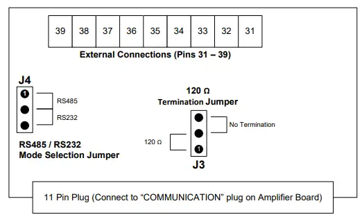
| Pin No. | Pin Name | Description |
| 31 | Analog Output | 0…20 mA, 0…10 mA, 2…10 mA, 4…20 mA |
| 32 | COM | Common ground connection |
| 33 | RS232 RX | Receive input for RS232 |
| 34 | RS232 TX | Transient output for RS232 |
| 35 | COM | Common ground connection |
| 36 | RS485 ( – ) | Inverting signal for RS485 |
| 37 | RS485 ( + ) | Non inverting signal for RS485 |
| 38 | RS232/485 Shield | Shield input for RS232 or RS485 |
| 39 | Chassis | Connection for coupling shield to chassis |
INSTALLING THE DAUGHTERBOARD
- Use the provided self-adhesive tape to secure the foam pad near the 11-pin COMMUNICATION connector.
- Remove the board support screw near the 11-pin COMMUNICATION connector to install the green chassis connection wire (with an eye washer). Connect the other end of the chassis connection wire to pin 39.
- Select operation mode RS485 or RS232 for the daughterboard
using J4. - For RS485 mode only: Select the termination (that is, 120 Ω or No termination) using J3.
NOTE: 120 Ω termination is typically required when the meter is the first or last device in the communication link.
NOTE: It is assumed all signal biasing is accomplished at the Modbus RTU master node. For biasing calculations, the receiver input impedance is 96 k Ω or 1/8 unit loads.
DISCONNECT THE INPUT POWER BEFORE ACCESSING THE EQUIPMENT. - Turn off the meter and insert the daughterboard into the keyed 11-pin COMMUNICATION connector on the amplifier.
CONFIGURING PORT B MODBUS RTU
The Modbus RTU Communication Daughterboard is a slave device that communicates over Port B. The following Port B settings are configurable from the meter’s menu manager.
| Setting | Options |
| Port address | 1 to 247 |
| Ext. port address | Not applicable for Modbus RTU daughterboard |
| Baud rate | 9600 (default), 19200, 38400 |
| Data bits | 5, 7, 8 (default) |
| Parity | None, Even (default), Odd |
| Stop bits | 1 (default), 2 |
To change the configuration of Port B to match your system requirements:
- Turn on the meter.
- Navigate to Main Menu > Communication > Port B Settings.
- Verify that the settings are an appropriate match for the application. If not, change the settings as necessary.
Please refer to the M2000 Modbus Memory Map Application Brief for accessible registers.
Control. Manage. Optimize.
ModMAG is a registered trademark of Badger Meter, Inc. Other trademarks appearing in this document are the property of their respective entities. Due to continuous research,
product improvements and enhancements, Badger Meter reserves the right to change product or system specifications without notice, except to the extent an outstanding
contractual obligation exists. © 2021 Badger Meter, Inc. All rights reserved. www.badgermeter.com
MAG-UM-01410-EN-05 (August 2021)


