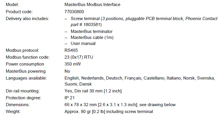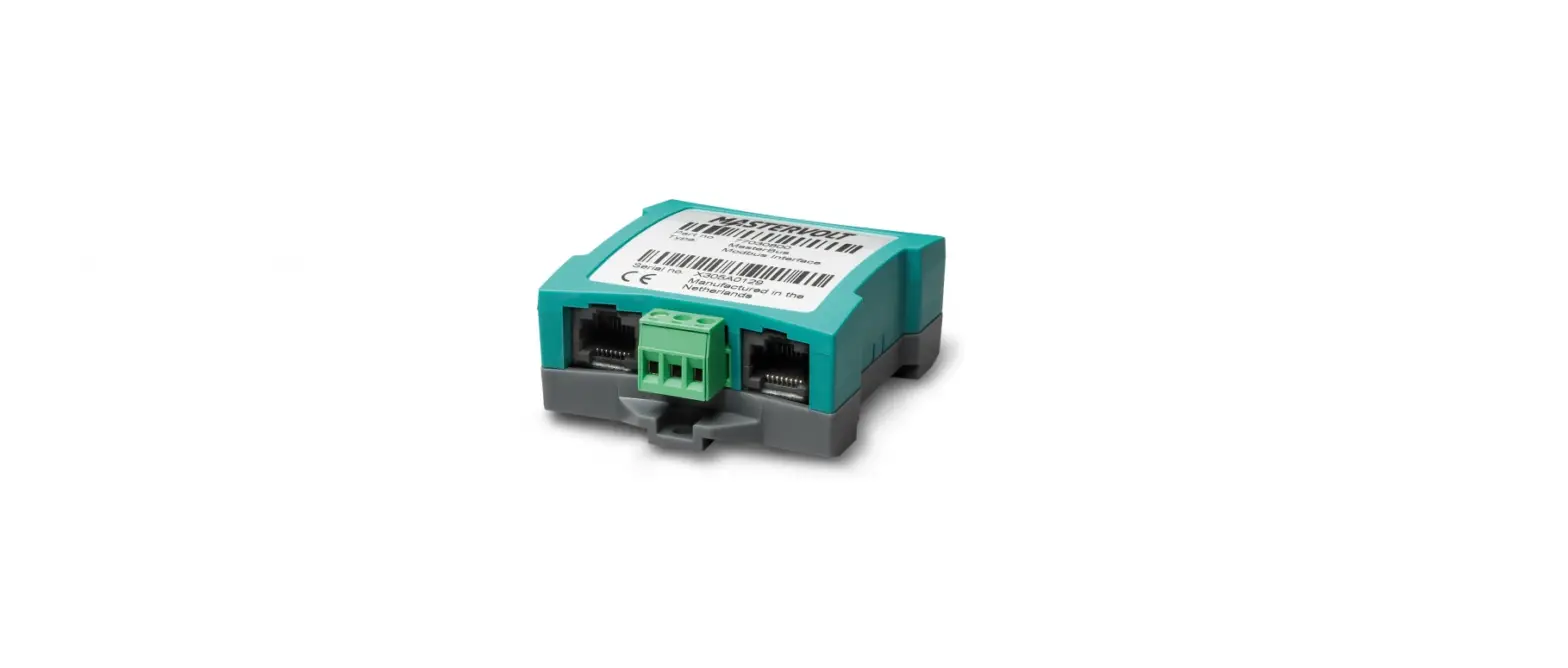
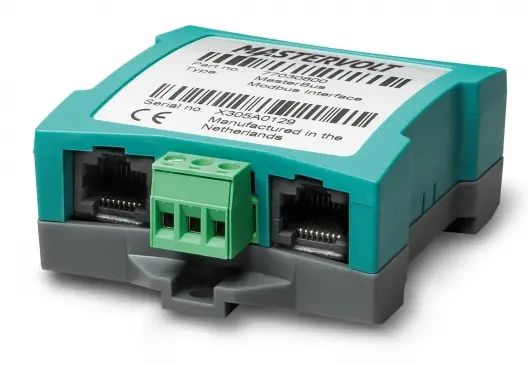
 MASTERVOLT 77030800 MasterBus Modbus Interface
GENERAL INFORMATION
Use of this manual
This manual serves as a guideline for the safe and effective operation of the MasterBus Modbus Interface. Keep this manual at a secure place!
Warranty
Advanced Systems Group (ASG) assures the product warranty of the Modbus Interface for two years after purchase, on the condition that the product is installed and used according to the instructions in this manual. Installation or use not according to these instructions may result in underperformance, damage or failure of the product and may void this warranty. The warranty is limited to the cost of repair and/or replacement of the product. Costs of labor or shipping are not covered by this warranty.
Liability
ASG can accept no liability for:
- consequential damage due to the use of the Modbus Interface;
- possible errors in the manuals and the results thereof;
- use that is inconsistent with the purpose of the product.
Disclaimer
Our products are subject to continual development and improvement. Therefore, additions or modifications to the products may cause changes to the technical data and functional specifications. No rights can be derived from this document. Please consult our online Terms & Conditions of Sale.
Correct disposal of this product
This product is designed and manufactured with high-quality materials and components, which can be recycled and reused. Please be informed about the local separate collection system for electrical and electronic products. Please act according to your local rules and do not dispose of your old products with your normal household waste. The correct disposal of your old product will help prevent potential negative consequences to the environment and human health.
INSTALLATION
- Step 1. Mount the Modbus Interface to any flat surface. The Modbus Interface comes with a DIN rail mount option. Alternatively, use the two mounting holes.
- Step 2. Insert the MasterBus cable (included, 1m) to integrate the interface into the MasterBus network. Make sure that the MasterBus network is properly terminated at the two ends with a terminator.
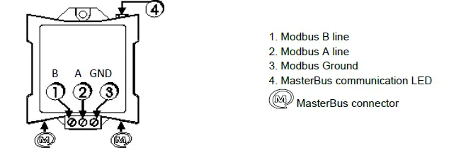
- Step 3. Connect the Modbus wires 1, 2 and 3 to the screw terminal.

- Step 4. A flashing LED (4) indicates that the MasterBus communication is working.
- Step 5. Use a Mastervolt USB Interface to connect a Windows PC (laptop or notebook) with MasterAdjust software, to configure the Modbus Interface.
OPERATION
The Modbus communicates via MasterBus. For information about MasterBus, see www.mastervolt.com.
| MasterBus functions | |||
| Monitoring | Description | Default | Range |
| State | Interface can be Communicating (active) or Idle (standby) | Idle | Idle/Communicating |
| Configuration | Description | Default | Range |
| Language | Set the Modbus menu language | English | See specifications |
| Device name | Any name you wish with 12 characters max. | INT MB Modbus | 12 characters max |
| Address | Device ID. Number to recognize the interface | 1 | 1-247 |
| Parity | The parity check of the interface can be set. None (1 stopbit) means no parity check in a 1 stopbit protocol. | Even | Even, Odd, None (1 stopbit), |
| None (2 stopbits), | |||
| Speed | Interface communication speed in Baud. Set a lower | 19200 | 9600, 19200, |
| speed if not all devices support 19200 Baud. | 115200 |
MODBUS INTERFACE CONFIGURATION
This chapter describes the configuration of the Modbus interface for communication between the MasterBus network and the Modbus network. The communication mode supported is RTU.
What you need
To configure the Modbus interface, you will need besides the Modbus itself:
- a Modbus cable from your Modbus network to the Modbus interface;
- a Windows PC;
- MasterAdjust software, free downloadable from www.mastervolt.com;
- Mastervolt USB Interface (product code 77030100).
MasterBus device address and variable
The master of the Modbus network can communicate with any individual MasterBus device variable for read or write action. For this communication, the MasterBus device address and the position of the variable are needed.
MasterBus Device Address
The MasterBus Device Address consists of 2 variables:
- IDB (18 bit value) and
- IDAL (5 bit value).
These two variables are read out by MasterAdjust.
- Monitoring: tab number 0
- Alarm: tab number 1
- History: tab number 2
- Configuration: tab number 3
Enter this number into TabNr to communicate with correct categories. The Variable number is the index connected to every variable in a category. Enter this number into Index. You now defined the position of the MasterBus device variable you want the Modbus to communicate with. See the following section for how to find these variables IDAL, IDB, TabNr and Index using MasterAdjust.
Finding IDB and IDAL
Righ-click INT DC Relay and select Property. The Device Property window will pop up.
Note: Write down the values found. You need them later to enter them into the PLC system.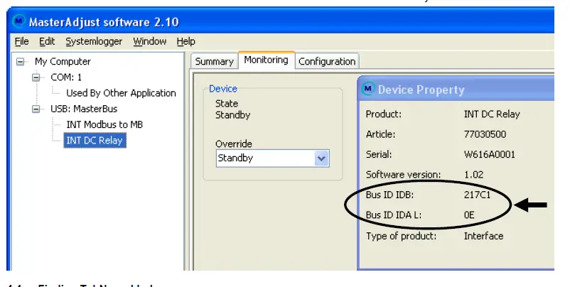
Finding TabNr and Index 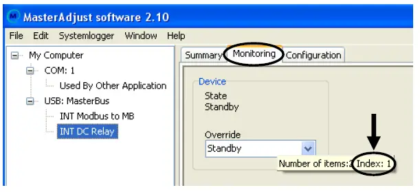
In this example, the Override variable is selected to communicate with. The following picture shows the Monitoring tab (TabNr = 0). The mouse hint (pops up when hovering the mouse pointer over the variable) of this variable shows Index: 1.
The required values are now: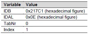
Entering the values into Modbus
After having written down the required values, you must enter these into your Modbus system. The next example shows how to enter the values and how to communicate with the chosen variable “Override” of MasterBus device “INT DC Relay”.
Modbus function code 23
The Modbus to MasterBus interface uses the Modbus function 23 communication protocol. See the Modbus Application Protocol Specification V1.1b at www.modbus.org for more details.
The data frame tables below, describe the variables used in Modbus function 23 (0x17) Read/Write Multiple Registers Protocol.
Request data frame
Request
| Address field | Function code (Function 23) | Data (Read Starting Address, etc.) | CRC (Error check) |
| 1 Byte | 1 Byte | 21 Bytes | 2 Bytes |
Response data frame
| Variable | Size | Value |
| Bus address | 1 Byte | Variable |
| Function code | 1 Byte | 0x17 (Fixed) |
| Read Starting Address | 2 Bytes | 0 (Fixed) |
| Quantity to Read | 2 Bytes | 6 (Fixed) |
| Write Starting Address | 2 Bytes | 0 = read / 1 = write |
| Quantity to Write | 2 Bytes | 6 (Fixed) |
| Write Byte Count | 1 Byte | 12 (Fixed) |
| IDAL 5 bit value | 1 Byte | Variable |
| IDB | 3 Bytes | Variable |
| TabNr | 2 Bytes | Variable |
| Index | 2 Bytes | Variable |
| Value | 4 Bytes | Variable |
| CRC | 2 Bytes | Calculated |
Response
| Address field | Function code (Function 23) | Data (Read Starting Address, etc.) | CRC (Error check) |
| 1 Byte | 1 Byte | 13 Bytes | 2 Bytes |
| Variable | Size | Value | |
| Bus address | 1 Byte | Variable | |
| Function code | 1 Byte | 0x17 | (Fixed) |
| Byte Count | 1 Byte | 0x0C | (Fixed) |
| IDAL 5 bit value | 1 Byte | Variable | |
| IDB | 3 Bytes | Variable | |
| TabNr | 2 Bytes | Variable | |
| Index | 2 Bytes | Variable | |
| Value | 4 Bytes | Variable | |
| CRC | 2 Bytes | Calculated | |
Example writing request
This is an example of a request to WRITE to the variable with:
- Monitoring (TabNr = 0);
- Variable index (Index = 1);
- MasterBus device IDAL = 0x0E ID;
- MasterBus device IDB = 0x0217C1.
Request example
| Request example | Response example | |||||
| Variable | Value | Range | Variable | Value | Range | |
| Bus address | 0x01 | [1…247] | Bus address | 0x01 | [1…247] | |
| Function code | 0x17 | Fixed | Function code | 0x17 | Fixed | |
| Read Starting Address Hi | 0x00 | Fixed | ||||
| Read Starting Address Lo | 0x00 | Fixed | ||||
| Quantity to Read Hi | 0x00 | Fixed | ||||
| Quantity to Read Lo | 0x06 | Fixed | ||||
| Write Starting Address Hi | 0 | Fixed | ||||
| Write Starting Address Lo | 1 | 0 = read / 1 = write | ||||
| Quantity to Write Hi | 0x00 | Fixed | ||||
| Quantity to Write Lo | 0x06 | Fixed | ||||
| Write Byte Count (Fixed) | 0x0C | Fixed | Byte Count (Fixed) | 0x0C | Fixed | |
| IDAL | 0x0E | [0…31] | IDAL | 0x0E | [0…31] | |
| IDB Hi | 0x02 | [0…3] | IDB Hi | 0x02 | [0…3] | |
| IDB Mi | 0x17 | [0…255] | IDB Mi | 0x17 | [0…255] | |
| IDB Lo | 0xC1 | [0…255] | IDB Lo | 0xC1 | [0…255] | |
| TabNr Hi | 0x00 | Fixed | TabNr Hi | 0x00 | Fixed | |
| TabNr Lo | 0x00 | [0…3] | TabNr Lo | 0x00 | [0…3] | |
| Index Hi | 0x00 | [0…255] | Index Hi | 0x00 | [0…255] | |
| Index Lo | 0x01 | [0…255] | Index Lo | 0x01 | [0…255] | |
| Value Lo (Float IEEE 754) | 0x00 | [0…255] | Value Lo (Float IEEE 754) | 0x00 | [0…255] | |
| Value Mi | 0x00 | [0…255] | Value Mi | 0x00 | [0…255] | |
| Value Hi | 0x80 | [0…255] | Value Hi | 0x80 | [0…255] | |
| Value Exponent | 0x3F | [0…255] | Value Exponent | 0x3F | [0…255] | |
| CRC Lo | 0x85 | [0…255] | CRC Lo | 0x94 | [0…255] | |
| CRC Hi | 0xFA | [0…255] | CRC Hi | 0xC1 | [0…255] | |
Exception codes
The Modbus function 23 communication protocol implements five default Modbus Exception Codes for incorrectly entered values. The table below describes the corresponding errors and proposes their solutions.
| Code | Error | Solution |
| 01 | The function code is wrong | Enter the Function 23 code: 0x17 |
| 02 | Wrong Read starting address. | Enter Read Starting Address: 0 |
| Wrong Write starting address. | Enter Write Starting Address: 0 or 1 | |
| 03 | Wrong Quantity to Read. | Enter Quantity to Read: 6 |
| Wrong Quantity to Write. | Enter Quantity to Write: 6 | |
| 04 | Packet size is too large or too small. | Enter a packet of exactly 25 bytes, incl. Modbus ID+CRC |
| IDAL value is too high | Enter a maximum 5-bit value. | |
| IDB value is too high | Enter a maximum 18-bit value. | |
| 05 | The time out error occurs when there is no response from MasterBus for three seconds. | Check if the MasterBus powering device is working and/or check the MasterBus wiring. |
Exception message
Below, the exception message is described and an example is shown.
| Exception message | Exception message example | |||
| Variable | Size | Value | Variable Value Range | |
| Bus address | 1 Byte | Variable | Bus address 0x01 [1…247] | |
| Function code | 1 Byte | 0x97 (Fixed) | Function code 0x97 Fixed | |
| Exception code | 1 Byte | Variable | Exception code 0x05 [1…5] | |
| CRC | 2 Byte | Calculated | CRC Lo 0x8E [0…255] | |
| CRC Hi 0x33 [0…255] |