![]()
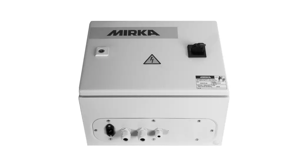
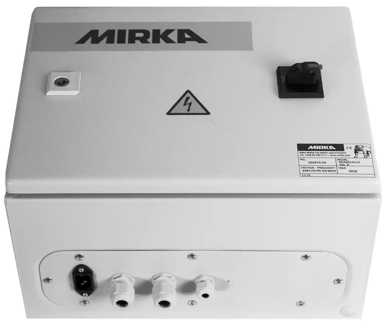
Mirka® Motor Drive Cabinet
Electrical manual
Warranty
Mirka warrants that your components are free from manufacturing and material defects.
Mirka components have a 1-year warranty starting from the date of purchase. Only manufacturing and material defects are covered by the warranty.
If a problem occurs caused by a manufacturing defect material or by workmanship, Mirka will repair your component free of charge in accordance with the warranty terms and conditions stated herein. To keep your component warranty valid the component must be used, maintained, and operated in compliance with the operating instructions.
Terms and conditions
Mirka’s component warranty cover defects in material and workmanship.
Components covered by the warranty:
- motor drive
- sanding unit
- polishing unit
- power supply
- communication gateway
Warranty does not cover:
- any damage caused or resulting from transport, receipt of delivery, installation, commissioning, misuse, neglect in usage or maintenance, accidents, exposure to extreme unacceptable ambient temperature, acids, water, unsuitable storage, excessive impact, or operation outside the rated specifications.
- defects caused by spare parts, accessories, or components other than Mirka’s original spare parts or accessories.
- normal wear and tear items such as backing pad, break the seal, exhaust fitting, bearings, rubber mount, signal cable, or power cable.
- components that have been: modified, repaired, or repair attempts (by other than Mirka authorized service), partly or completely disassembled components.
No other than Mirka has the authority to change, extend or add to given warranty terms and conditions. The manufacturer cannot be held responsible for consequential damages compensations for downtime, production loss, injuries or property damages. A warranty claim must be submitted with a short a delay as possible. A warranty claim must be submitted within the warranty period.
Installation overview
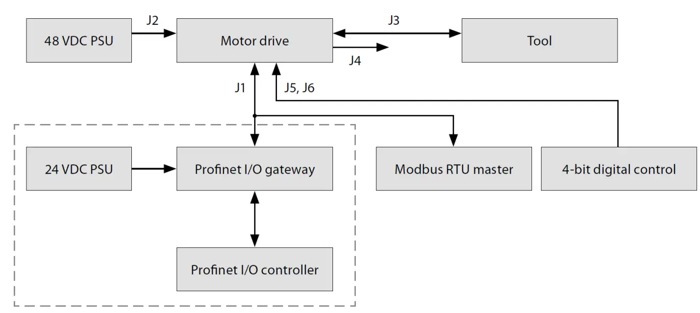
General
- Connect the 48 VDC power supply to the motor drive (J2 connector).
- Connect the tool to the motor drive (J3 connector).
Modbus RTU interface - Use the J1 connector to connect the motor drive to the Modbus RTU bus. Profinet I/O gateway to Modbus RTU interface
- Connect the 24 VDC power supply to the gateway and connect the DSUB-9 adapter cable between the gateway (X2 connector) and the motor drive (J1 connector).
Digital control interface - Use the J6 connector to connect the common GND between the systems.
- Use the J5 connector to select the operation using the four digital input signals.
Relay interface - The N/O relay pins are available on the J4 connector.
Component spare part codes
Name | Mirka code |
| Power supply 48 V | MIA6513211 |
| Power supply 24 V | MIA6513411 |
| Hilscher NT 50-RS-EN | MIA6513311 |
| Hilscher NT 50-RS-EN adapter cable | MIA6514011 |
| Motor drive | MIA6513112 |
| Shielded cable for the tool (10 m) | MIA6512311 |
Technical data for motor drive
| Input | |
| Nominal input voltage | 48 VDC |
| Input voltage range | 46 – 50 VDC |
| Input | |
| Maximum input current | 10 A |
| Rated power | 350 W |
| Speed control | |
| Speed range | 4000 – 10000 rpm |
| Protection | |
| Overload protection | Yes |
| Overheat protection | Yes |
| Interfaces | |
| Input interfaces | Modbus RTU (RS-485)Profinet I/O (gateway module) 4-bit digital inputs (15-33 VDC) |
| Output interfaces | Single pole, non-latching N/O relay, 250 VAC/ 125 VDC, 10 A |
| Environmental | |
| Ambient temperature | 0 – 40 °C |
| Humidity | Maximum 95% RH, non-corrosive, no dripping water |
| Storage temperature | -20 to 80 °C |
| Dimensions | |
| Motor drive cabinet | 380 x 300 x 210 mm (W x H x D) |
| Motor drive | 72 x 30 x 200 mm (W x H x D) |
| Motor drive mounted in DIN -rail holder | 95 x 55 x 210 mm (W x H x D) |
Safety instructions
![]() The electrical installation must be carried out by a competent electrician!
The electrical installation must be carried out by a competent electrician!![]() The motor drive has been designed for fixed installations only.
The motor drive has been designed for fixed installations only.![]() Do not perform any voltage withstand tests on any part of the motor drive or the tool. Product safety has been fully tested at the factory.
Do not perform any voltage withstand tests on any part of the motor drive or the tool. Product safety has been fully tested at the factory.![]() Ground yourself with an anti-static wristband before touching the motor drive (setting jumpers and similar actions) to avoid electrostatic voltage discharge damage to the motor drive.
Ground yourself with an anti-static wristband before touching the motor drive (setting jumpers and similar actions) to avoid electrostatic voltage discharge damage to the motor drive.
Warnings![]() Make sure that all the AC-DC power supplies are properly earthed and that the motor drive cannot come in contact with live mains voltage.
Make sure that all the AC-DC power supplies are properly earthed and that the motor drive cannot come in contact with live mains voltage.![]() An external emergency stop circuit is recommended.
An external emergency stop circuit is recommended.
Before running the tool![]() Before starting the tool, check that the tool is mounted properly and ensure that the motor drive is installed properly.
Before starting the tool, check that the tool is mounted properly and ensure that the motor drive is installed properly.
Motor drive overview
Motor drive PCB connectors, buttons, jumpers, indicators, mounting holes, and dimensions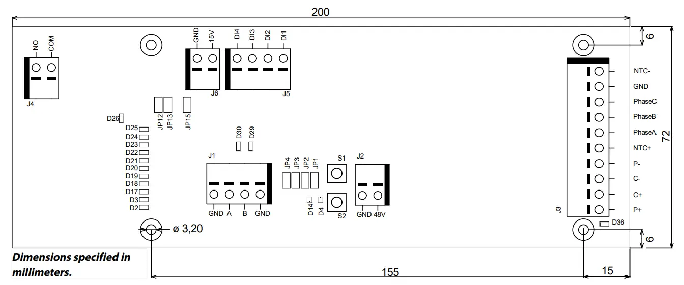
The motor drive PCB comes mounted in a DIN-rail holder that can be attached to a standard 35 x 7.5mm EN50022 DIN-rail, but the motor drive PCB can be removed from this holder and mounted using the mounting holes instead. If the mounting holes are used, then it is recommended to use 20 mm metal standoffs and 10 mm M3 screws when mounting the motor drive PCB.
It is recommended to use 10 mm ferrules with a plastic sleeve for each wire that is attached to any of the connectors. The wires can then easily be pushed into the connectors and released with the help of a small flat-head screwdriver (3.5 mm blade width, 0.6 mm blade thickness).
Connector description
| Connector | PIN | Description |
| J1 | GND | GND |
| J1 | A | Modbus RTU RS-485 (A) |
| J1 | B | Modbus RTU RS-485 (B) |
| J1 | GND | GND |
Connector | PIN | Description |
| J2 | GND | GND |
| J2 | 48V | 48 VDC input |
| Connector | PIN | Description |
| J3 | P+ | P+ |
| J3 | C+ | C+ |
| J3 | C- | C- |
| J3 | P- | P- |
| J3 | NTC+ | NTC+ |
| J3 | Phase A | Phase A |
| J3 | Phase B | Phase B |
| J3 | Phase C | Phase C- |
| J3 | GND | GND |
| J3 | NTC- | NTC- |
| Connector | PIN | Description |
| J4 | COM | Relay COM |
| J4 | NO | Relay NO |
| J5 | DI1 | Digital spped control input bit 1 |
| J5 | DI2 | Digital spped control input bit 2 |
| J5 | DI3 | Digital spped control input bit 3 |
| J5 | DI4 | Digital spped control input bit 4 |
| Connector | PIN | Description |
| J6 | 15V | 15 VDC output |
| J6 | GND | GND |
Button description
| Button………………………………………………Description | |
| S1 | Self-test button |
| S2 | Reset button |
Indicator description
| Indicator…………………………………………………………………………………………Description | |
| D2 | Speed set-point indicator, lit if ≥ 4,000 rpm. Modbus RTU slave address indicator bit 1. |
| D3 | Speed set-point indicator, lit if ≥ 5,000 rpm. Modbus RTU slave address indicator bit 2. |
| D4 | Tool status indicator. Lit red when the tool is stopped, lit green when the tool is running. |
| D14 | Motor drive state indicator. Lit green when motor drive is in ON-state. Blinking green when motor drive is in OFF-state. |
| D17 | Speed set-point indicator, lit if ≥ 6,000 rpm. Modbus RTU slave address indicator bit 3. |
| D18 | Speed set-point indicator, lit if ≥ 7,000 rpm. Modbus RTU slave address indicator bit 4. |
| D19 | Speed set-point indicator, lit if ≥ 8,000 rpm. Modbus RTU slave address indicator bit 5. |
| D20 | Speed set-point indicator, lit if ≥ 9,000 rpm. Modbus RTU slave address indicator bit 6. |
| D21 | Speed set-point indicator, lit if ≥ 10,000 rpm. Modbus RTU slave address indicator bit 7. |
| D22 | Modbus RTU slave address indicator bit 8. |
| D23 | Lit if D2–D3, D17–D22 indicator mode is Modbus RTU slave address. |
| D24 | Lit if digital speed control interface is enabled. |
| D25 | Lit if the alarm status flag is set. |
| D26 | Relay status indicator. |
| D29 | Modbus RTU receives an indicator. |
| D30 | Modbus RTU transmits indicator. |
Speed set-point display
| RPM | BIT 8 D22 | BIT 7 D21 | BIT 6 D20 | BIT 5 D19 | BIT 4 D18 | BIT 3 D17 | BIT 2 D3 | BIT 1D2 |
| ≥ 4,000 | – | OFF | OFF | OFF | OFF | OFF | OFF | ON |
| ≥ 5,000 | – | OFF | OFF | OFF | OFF | OFF | ON | ON |
| ≥ 6,000 | – | OFF | OFF | OFF | OFF | ON | ON | ON |
| ≥ 7,000 | – | OFF | OFF | OFF | ON | ON | ON | ON |
| ≥ 8,000 | – | OFF | OFF | ON | ON | ON | ON | ON |
| ≥ 9,000 | – | OFF | ON | ON | ON | ON | ON | ON |
| ≥ 10,000 | – | ON | ON | ON | ON | ON | ON | ON |
Modbus RTU slave address display
| BIT 8 | BIT 7 | BIT 6 | BIT 5 | BIT 4 | BIT 3 | BIT 2 | BIT 1 |
| D22 | D21 | D20 | D19 | D18 | D17 | D3 | D2 |
Jumper description
| Jumpers……………………………………………………..Default……………………………………………………………………………………Description | ||
| JP1 | Not set | Reserved for future use |
| JP2 | Not set | If set, a terminating resistor of 270 Ω is connected across Modbus RTU pins A and B. |
| JP3 | Not set | If set, a pull-down resistor of 10 kΩ is connected to Modbus RTU B-pin. |
| JP4 | Not set | If set, a pull-up resistor of 10 kΩ is connected to Modbus RTU A-pin. |
| JP12 | Not set | If set, the digital speed control feature is enabled. |
| JP13 | Not set | If set, D2–D3, D17–D22 indicators will output the current Modbus RTU slave address instead of the speed set-point. |
| JP15 | Not set | Reset to factory settings. |
Tool cable connector pinout
Pin (color, size) | Description |
| PE (green-yellow,1.0mm2) | Not in use |
| 1 (brown, 1.00 mm²) | Phase A |
| 2 (blue, 1.00 mm²) | Phase B |
| 3 (black, 1.00 mm²) | Phase C |
| A (grey, 0.25 mm²) | C- |
| B (pink, 0.25 mm²) | C+ |
| C (green, 0.25mm²)C(yellow,0.25mm²) | P–NTC– |
| D (brown, 0.25 mm²) | NTC+ |
| E (white, 0.25 mm²) | P+ |
NOTE! NTC– and P– are connected together to the same PIN inside the connector.
| PIN (color) | Description |
| 1 (white, WH) | GND |
| 4 (brown, BN) | Modbus RTU (A, RxD / TxD+) |
| 5 (green, GN) | Modbus RTU (B, RxD / TxD–) |
| SHIELD | Shield |
Modbus RTU
Modbus RTU over RS-485 is used to communicate with the motor drive. The motor drive is configured as a Modbus RTU slave device and the default slave address is 86. The slave address can be changed if it conflicts with another Modbus RTU slave device.
The J1 connector on the motor drive is used for Modbus RTU communication. A shielded twisted pair cable is recommended and the shield should be earthed only at one point, normally at the master device. The A-pin of the J1 connector is equivalent to RxD / TxD+ and the Bi-pin is equivalent to RxD / TxD.
RS-485 configuration
| BAUD RATE | 19200 |
| PARITY | EVEN |
| STOP BITS | 1 |
| DATA BITS | 8 |
Coil registers (F1, F5, F15)
Address | Data type | Name | Description |
| 00001 – 00012 | Uint16 | Digital outputs | Coils 1–11 are reserved for future use. Coil 12 is the relay located on the motor drive. |
Input registers (F4)
| Adress……………………………………………Data type…………………………………..Name………………………………………………Description | |||
| 30001 | Uint16 | Drop RPM count | The number of times the speed has dropped from set-point by more than 25%. |
| 30002 | Uint16 | Warm tool count | The number of times the tool temperature has exceeded the “warm” limit, 79°C. |
| 30003 | Uint16 | Warm motor drive count | The number of times the motor drive temperature has exceeded the “warm” limit, 73°C. |
| 30004 | Uint16 | Hot tool count | The number of times the tool temperature has exceeded the “hot” limit, 134°C. |
| 30005 | Uint16 | Hot motor drive count | The number of times the motor drive temperature has exceeded the “hot” limit, 117°C. |
| 30006 | Uint16 | Stop tool count | The number of times the tool temperature has exceeded the “stop” limit, 142°C. |
| 30007 | Uint16 | Stop motor drive count | The number of times the motor drive temperature has exceeded the “stop” limit, 123°C. |
| 30008 | Uint16 | Voltage out of range count | The number of times the input voltage has not been within 44 to 52 VDC. |
| 30009 | Uint16 | Over-current low count | The number of times the current has exceeded 15.1 A. |
| 30010 | Uint16 | Over-current medium count | The number of times the current has exceeded 18.2 A. |
| 30011 | Uint16 | Usage count long | The number of times the run time has been more than 60 seconds. |
| 30012 | Uint16 | Usage count medium | The number of times the run time has been between 20 and 60 seconds. |
| 30013 | Uint16 | Usage count short | The number of times the run time has been less than 20 seconds. |
| 30014 | Uint16 | Usage time hours | Hours are part of usage time. |
| 30015 | Uint16 | Usage time minutes | Minutes part of usage time. |
| 30016 | Uint16 | Usage time seconds | Seconds part of usage time. |
| 30017 | Int16 | Average current | The average current in mA. |
| 30018 | Uint16 | Average speed | Average speed in RPM. |
| 30019 | Uint16 | Tool temperature | Tool temperature in °C. |
| 30020 | Uint16 | Motor drive temperature | Motor drive temperature in °C. |
| 30021-30030 | Char[20] | Firmware version | Firmware version and build date, e.g. “2.0 Jan 18 14:00”. |
| 30031–30039 | Char[18] | Part version | Part version and motor drive identification number, e.g. “AI1.3 123456” |
| 30040–30046 | Char[14] | Motor drive serial number | Motor drive serial number, e.g. “749474379001” |
Adress | Data type | Name | Description |
| 30047 | Uint16 | Alarm status flag | Alarm status flag can at any given time hold acombination of values from the list below. Check the individual bits to determine the type of alarms that are currently triggered. This flag is automatically cleared after 5 seconds if the cause of the alarm trigger is no longer present. 0x0000 = Not triggered 0x0001 = Tool overheated 0x0002 = Motor drive overheated 0x0004 Over-current 0x0008 = Under-voltage 0x0010 = Over-voltage 0x0020 = Self-test running 0x0040 = RPM drop 0x0080 = High current 0x0100 = Tool change in progress 0x0200 = Possible tool wiring fault 0x0400 = Factory reset mode 0x0800 = Write protection dis- abled |
Holding registers (F3, F6, F16)
Address | Data type | Name | Description |
| 40001-40010 | Char[20] | Device name | Max length 19 printable characters, e.g. “AIMD 749474379001”. |
| 40011 | Uint16 | Speed set-point | Speed set-point, not the actual speed, between 4,000–10,000 RPM. |
Address | Data type | Name | Description |
| 40012 | Uint16 | Operation | Motor drive state, can be a combin- ation of the following:0x0001 = RUN 0x0002 = STOP 0x0004 = ON= 0x0008 = OFF 0x0010 = TOOL CHANGE START 0x0020 = TOOL CHANGE END 0x0040 = WRITE PROTECTION DISABLE 0x0080 = WRITE PROTECTION EN- ABLE NOTE! When writing a new state value, the value can only be a single state, not a combination of multiple states, e.g. ON+RUN can- not be written simultaneously. |
| 40013 | Uint16 | Slave address | Defaults to 86 but can be changed if needed. |
Profinet I/O gateway (Hilscher NT 50-RS-EN)
If the motor drive needs to be connected to a Profinet I/O device the Hilscher NT 50-RS-EN gateway can be used. The gateway is connected to the motor drive via the DSUB-9 connector on the gateway and the J1 connector on the motor drive. Below is the pinout for the DSUB-9 (X2 connector) found on the gateway:
| RS-485 | PIN | Signal | Descriptions |
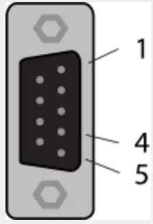 | 1 | GND | Reference potential, the ground of power supply |
| 4 | RxD / TxD+ | Receive data / Transmit data positive | |
| 5 | RxD / TxD– | Receive data / Transmit data negative |
A pull-up resistor of 10 k is internally connected in the gateway to “RxD / TxD+”.
A pull-down resistor of 10 k is internally connected in the gateway to “RxD / TxD”.
Detailed documentation about the gateway and configuration tools can be downloaded from the Hilscher website:
https://www.hilscher.com/products/product-groups/gateways/for-the-control-cabinet-ip20/entry-level-gateways/nt-50-rs-enmbrpns/
Configuration
The gateway comes pre-configured from Mirka as a Profinet I/O slave device. The “SYCON.net” software from Hilscher can be used to re-configure the device. The “Ethernet Device Setup” software from Hilscher can be used to change the network configuration, use the DCP protocol. The IP address usually needs to be re-assigned after a configuration change.
Default network configuration
| IP ADDRESS | 192.168.2.191 |
| SUBNET MASK | 255.255.255.0 |
| DEFAULT GATEWAY | 0.0.0.0 |
| DEVICE NAME | nt50enpns |
Profinet I/O to Modbus RTU signal mapping
| Name | Modbus reregister | Data length | Trigger | Profinet I/O | Data length |
| SetRelay | 00012 | 1 coil | Changed data | 1 | 1 byte out |
| SetSpeedRegister | 40011 | 1 register | Changed data | 2 | 1 word out |
| SetOperationRegister | 40012 | 1 register | Changed data | 3 | 1 word out |
| DeviceName | 40001-40010 | 10 registers | Cyclically 10 sec. | 4 | 10 words in |
| CommonInputs | 30017-30020 | 4 registers | Cyclically 1 sec. | 5 | 4 words in |
| MiscInputs | 30001–30016 | 16 registers | Cyclically 5 sec. | 6 | 16 words in |
| AlarmStatus | 30047 | 1 register | Cyclically 1 sec. | 7 | 1 word in |
| firmware version | 30021–30030 | 10 registers | Cyclically 10 sec. | 8 | 10 words in |
| PartVersionSerialNumber | 30031–30046 | 16 registers | Cyclically 10 sec. | 9 | 16 words in |
| GetSpeedRegister | 40011 | 1 register | Cyclically 1 sec. | 10 | 1 word in |
| GetOperationRegister | 40012 | 1 register | Cyclically 1 sec. | 11 | 1 word in |
| ReadCoils | 00001–00012 | 12 coils | Cyclically 1 sec. | 12 | 2 bytes in |
Siemens TIA Portal V14 gateway mapping example
Below is a screenshot from TIA Portal V14 showing how the gateway can be mapped into the system. Use the GSDML file that is downloadable from the Hilscher website to add support for the Hilscher NT 50-RS-EN gateway into your system. Basic operation for Modbus RTU
The motor drive must be in ON-state before the tool can be started. The very first command that should be sent to the motor drive is the ON-state command. It is not mandatory to send the OFF-state command before removing power from the motor drive.
When the motor drive is in ON-state the speed set-point value can be written and the state can be set to RUN-state by sending the RUN-state command. This will cause the tool to run at the set-point speed. To stop the tool, set the motor drive to STOP-state by sending the STOP-state command.
It is recommended to continuously monitor the average speed, average current, tool temperature, motor drive temperature and the alarm status flag. This will help to detect if there are any issues present during operation.
Example sequence for starting and stopping the tool:
- Write 4 (0x0004) to the “Operation” register, this will set the motor drive to ON-state.
- Write 4000 (0x0FA0) to the “Speed set-point” register, this will set the set-point speed to 4,000 rpm.
- Write 1 (0x0001) to the “Operation” register, this will set the motor drive to RUN-state and the tool will start running.
- Write 2 (0x0002) to the “Operation” register, this will set the motor drive to STOP-state and the tool will stop running.
- Write 8 (0x0008) to the “Operation” register, this will set the motor drive to OFF-state.
Digital interface
The motor drive can also be controlled via the digital interface instead of Modbus RTU, but with the added drawback that there is no feedback when using the digital interface. To enable the digital interface, the JP12 jumper needs to be set.
Connector J5 is used as input for the digital interface. The input is considered high if a voltage between 1533 VDC is applied to the input pin. The input is considered low if the voltage is below 12 VDC or if the input is left floating. The GND pin of connector J6 must be connected between the systems. The J6 connector can also be used to provide a 15 VDC control voltage if needed.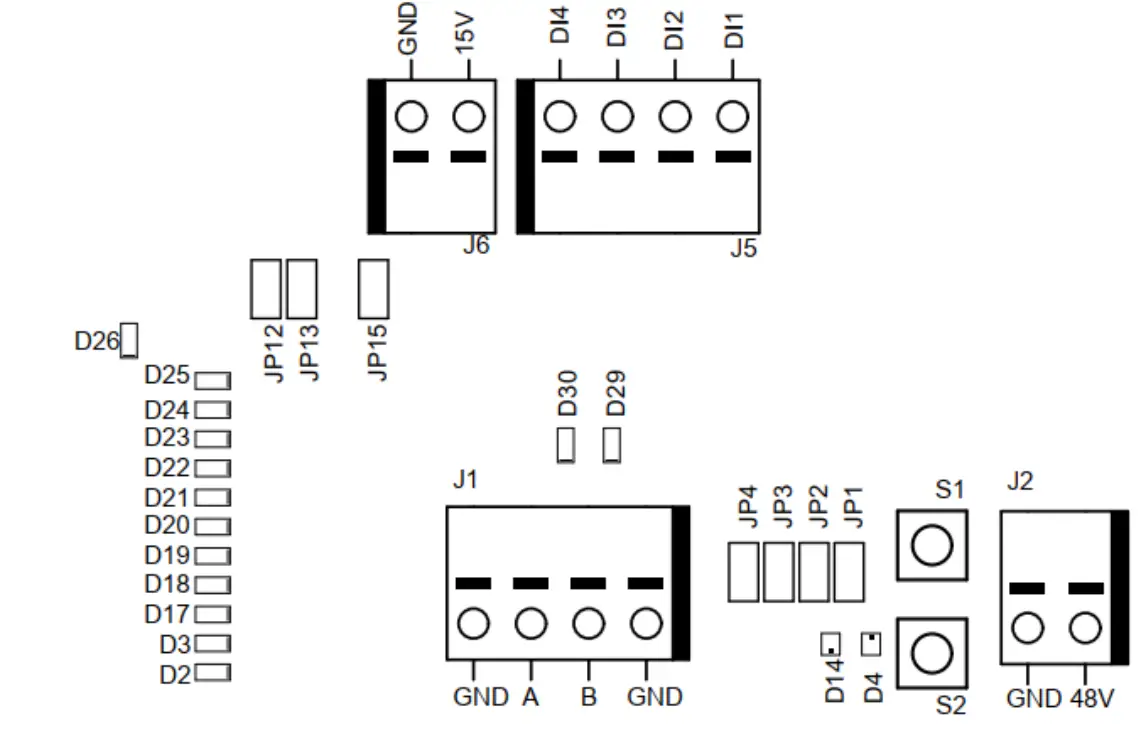
Digital interface operations
| J5.1 – DI1 | J5.2 – DI2 | J5.3 – DI3 | J5.4 – DI4 | Operation |
| 0 | 0 | 0 | 0 | Stopped |
| 1 | 0 | 0 | 0 | 4,000 rpm |
| 0 | 1 | 0 | 0 | 4,500 rpm |
| 1 | 1 | 0 | 0 | 5,000 rpm |
| 0 | 0 | 1 | 0 | 5,500 rpm |
| 1 | 0 | 1 | 0 | 6,000 rpm |
| 0 | 1 | 1 | 0 | 6,500 rpm |
| 1 | 1 | 1 | 0 | 7,000 rpm |
| 0 | 0 | 0 | 1 | 7,500 rpm |
| 1 | 0 | 0 | 1 | 8,000 rpm |
| 0 | 1 | 0 | 1 | 8,500 rpm |
| 1 | 1 | 0 | 1 | 9,000 rpm |
| 0 | 0 | 1 | 1 | 9,500 rpm |
| 1 | 0 | 1 | 1 | 10,000 rpm |
| 0 | 1 | 1 | 1 | Run, no speed change |
| 1 | 1 | 1 | 1 | Run, no speed change |
Self-test function
While holding down the S1 button the motor drive will perform a quick self-test. The alarm status flag will be set to 6 (self-test running). The indicators D4 and D14 will blink green if temperatures and voltages are within the limits. If the temperatures or voltages are not within the limits then the indicators will blink red.
Reset function
The reset button S2 can be pressed momentarily to reset the motor drive. This is essentially the same as turning the power off and on again.
Factory reset function
The configuration stored in the motor drive can be reset to factory defaults if needed. This will restore the factory assigned Modbus slave address and the last known tool configuration will be reset to factory defaults. Follow these steps to do a factory reset: 1. Set jumper JP15. 2. Press and hold S2 for 5 seconds. 3. Remove JP15.
Write protection
The holding registers for “Device name” and “Slave address” are normally read-only to prevent accidental writes to these registers. If any of these registers need to be changed, follow these steps: 1. Write 64 (0x0040) to the “Operation” register to disable the write protection. 2. Write the new value to “Device name” or “Slave address” holding registers. 3. Write 128 (0x0080) to the “Operation” register to enable the write protection.
Safety stop / E-Stop
The motor drive itself does not have any inputs for detecting or reacting to an external safety stop / E-Stop signal. A suitable contractor can be used placed near the motor drive to connect or disconnect the tool cable phase A, B, and C wires.
On the fly tool change function
Multiple tools can be used with the same motor drive but only one tool can be connected to the motor drive at any given time. When changing from one tool to the next, follow these steps:
- Stop the tool by writing 2 (0x0002) to the “Operation” register.
- Write 16 (0x0010) to the “Operation” register to let the motor driver know that you are intending to disconnect the currently attached tool.
- Wait 1 second before disconnecting the currently attached tool from the motor drive.
- Disconnect the currently attached tool from the motor drive.
- Connect the next tool to the motor drive.
- Write 32 (0x0020) to the “Operation” register to let the motor driver know that the new tool has been attached.
- Wait 1 second before starting the new tool.
Protection features
| Protection mode…………………………………………………………………Reason | |
| Tool enters reduced power | The motor drive is over 117°C Tool temperature is over 134°C Excessive load |
| Tool stops completely | The motor drive is over 123°C Tool temperature is over 142°C Overload condition |
Troubleshooting guide
| Symptom…………………………………………………………………………………………Recommended procedures | |
| The motor drive does not power on. | Check that 48 VDC is present on J2 and that the polarity is correct. |
| The tool does not start. | Check that the motor drive is in ON-state (D14 is not blinking). Check that the motor drive is in RUN-state (D4 is lit green). Check the cable assembly for the tool: are the pins properly connected? |
| Tool suddenly stops. | Check the alarm status flag. Check the motor drive and tool temperatures. Check if the tool is being overloaded. |
| Modbus RTU communication is not working. | Check that JP1 and JP12 are not set. Check the baud rate, parity, stop bits, and data bits. Check the transmit/receive indicators D29 and D30; this blink when there is activity on the bus Check that the A-pin and Bi-pin are connected properly. Check whether the addition of a terminating resistor (JP2), A-pin pull-down resistor (JP3), Bi-pin pull-up resistor (JP4) solves the issue. Check the slave address (set the JP13 jumper and use indicators D2–D3, D17–D22 to read the current address). |
| Profinet I/O gateway communication is not working. | Check that JP1 and JP12 are not set. Check the gateway network configuration Check the gateway Modbus RTU to Profinet I/O mapping configuration. Check the 24 VDC power supply. Check the Modbus RTU adapter cable is connected properly. Check that JP1 is not set. |
| Digital speed controller interface is not working. | Check that JP1 is not set. Check that JP12 is set. Check the voltage on high input, it should be between 15–33 VDC. Check the voltage on low input, it should be close to zero volts. Check the GND connection. |
| Indicator D36 is lit red, or the tool speed is too fast/slow. | Check C+/C-/P+/P– wiring on J3. |

Mirka Ltd Finland
USA Mirka USA Inc.
For contact information, please visit www.mirka.com
 Dedicated to the finish
© Mirka ltd 03-2021


