![]() TCW181B-CM
TCW181B-CM
Ethernet digital 10 module Revision
4.10 / October 2022
USER MANUAL 
Short description
TCW181B-CM is an Ethernet digital IO module. It has 8 relays with NO/NC contacts and 1 digital input.
The device has an embedded HTTP server for easy setup. For a stand-alone application, there is no need for external software for setup. A standard browser like IE, Chrome, Firefox, etc. can be used. TCW181B-CM supports HTTP API and SNMP protocol for M2M communication. With these protocols, the device can be part of control and monitoring systems.
A large number of relays with normally open and normally closed contacts makes the device suitable for the simultaneous management of several parallel processes.
Features
- Password protected web-based configuration and control;
- 1 digital input with “logic level” and “dry contact” modes;
- 8 relays with NO and NC contacts;
- On/Off and Pulse modes;
- LED indicators for relay state
- SNMP v.1 support;
- Sending SNMP Traps messages under certain conditions;
- Sending E-mail messages under certain conditions;
- SMTP with authorization (SSL is not supported);
- HTTP and SNMP port changing;
- HTTP and XML API commands;
- Remote firmware update;
- DIN-Rail mountable.
Specifications
- Physical characteristics
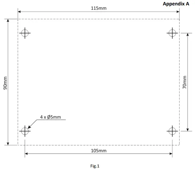
Dimensions: 115 x 90 x 40 mm
Weight: 205 g - Environmental limits
Operating тemperature range: -20 to 55°C
Storage temperature range: -25 to 60°C
Operating relative humidity range: 5 to 85% (non-condensing) - Warranty
Warranty period: 3 years - Power supply
Operating voltage range (including -15/+20% according to IEC 62368-1): 10 to 14 VDC
Current consumption (with all relays ON): 0.37 A @ 12 VDC - Ethernet connectivity
10 Mbit/s transfer rate
Half-duplex mode only
Auto-negotiation not supported - Digital input
Isolation: Non-isolated
Mode: Dry contact or Logic level
Maximum input voltage: +5.5VDC
Minimum input voltage for high logic level: +2.5VDC
Maximum input voltage for low logic level: +0.8VDC
Sampling rate: 10mS
Digital filtering time interval: 30mS - Relay outputs
Type: Form C (N.O. and N.C. contacts)
Contact current rating: 3 A @ 24 VDC/30 VAC (resistive load)
Initial insulation resistance: 100 mega-ohms (min.) @ 500 VDC
Mechanical endurance: 10 000 000 operations
Electrical endurance: 100 000 operations @ 3 A resistive load
Contact resistance: 50 milli-ohm max. (initial value)
Minimum pulse output: 1 Hz at rated load
CAUTION: The device does not contain any internal overcurrent protection facilities on the relays’ contact lines.
External fuses or short circuit current limiting circuit breakers, rated to 3 Amps, are to be used for overcurrent protection of the connecting lines - Internal FLASH memory
Endurance: 100 000 cycles (Every relay status and settings change is a memory cycle.)
Connectors
The location of the connectors and LED’s are shown below: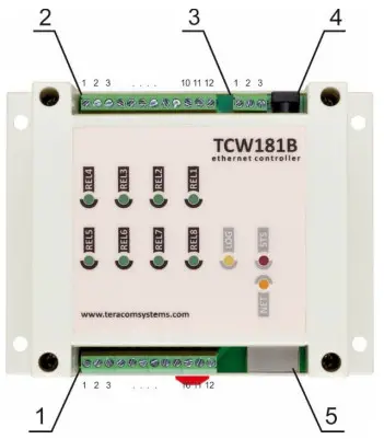
| Connector 1 Pin 1/2/3 – NO/COM/NC of Relay5 Pin 4/5/6 – NO/COM/NC of Relay6 Pin 7/8/9 – NO/COM/NC of Relay7 Pin 10/11/12 – NO/COM/NC of Relay8 | Connector 2 Pin 1/2/3 – NC/COM/NO of Relay4 Pin 4/5/6 – NC/COM/NO of Relay3 Pin 7/8/9 – NC/COM/NO of Relay2 Pin 10/11/12 – NC/COM/NO of Relay1 |
| Connector 3 Pin 1 – Digital input (DI)* Pin 2 – Ground Pin 3 +12VDC | Connector 4 – Power – 2.1×5.5mm connector, central positive Connector 5 – Ethernet – RJ45 |
* Operating mode is selected by jumper DI on PCB – closed for “dry contact” and open for “logic level”. By default, the jumper is closed.
LED indicators
The following indicators show the status of the controller:
- REL1-REL8 (green) – these LEDs are ON when the corresponding relay is activated (the NO contact is closed);
- STS (red) – flashes when the main program is executed;
- LOG (yellow) – the LED is ON when somebody is logged via the WEB interface;
- NET (green/red) – red when the device is linked, yellow when there is an activity.
Powering
TCW181B-CM is designed to be supplied by adapter SYS1421-0612-W2E or similar, intended for use in the conditions of overvoltage category II, and priory assessed for compliance with safety requirements. The power supply equipment shall be resistant to short circuit and overload in a secondary circuit. When in use do not position the equipment so that it is difficult to disconnect the device from the power supply.
Installation
This device must be installed by qualified personnel.
This device must not be installed directly outdoors.
The installation consists of mounting the device, connecting to an IP network, connecting inputs and outputs, providing power and configuring via a web browser.
TCW181B-CM can be wall or flat, nonflammable surface mounted, in a clean and dry location room. Ventilation is recommended for installations where the ambient air temperature is expected to be high.
Mount the device to a wall by using two plastic dowels 8x60mm (example Worth GmbH 0912 802 002) and two dowel screws 6x70mm (example Worth GmbH 0157 06 70). Attach the screws to the surface vertically. See Appendix-A, fig. 1 for mechanical details.
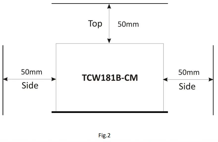
Maintain spacing from adjacent equipment. Allow 50 mm of space on all sides, as shown in fig.2 in Appendix A, this provides ventilation and electrical isolation TCW181B-CM can be mounted to a standard (35mm by 7.55mm) DIN rail. Attach the controller to the DIN rail by hooking the hook on the back of the enclosure to the DIN rail and then snap the bottom hook into place.
Configuration
Please follow the steps below for proper installation :
- Mount the controller in a dry and ventilated place.
- Connect the Ethernet port to a 10/100MB Ethernet network. For direct connection to a PC, use a “crossover” cable.
- Connect the I/O pins of the controller according to the required application.
- Connect the power supply.
If the red LED blinks, the power supply is OK. By default TCW181B-CM comes with the following network settings:
IP address: 192.168.1.2, Subnet Mask: 255.255.255.0, Default Gateway: 192.168.1.1
Communication with TCW181B-CM can be established by assigning a temporary IP address to the computer. This address should be on the same network (for example 192.168.1.3). To get access to the web interface, you should type http://192.168.1.2 into the browser. 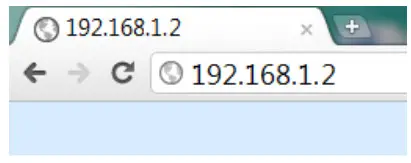 If the network settings are correct, the “Login” page will appear.
The web-based interface allows configuration, monitoring, and control.
8.1 Login page
 After opening the “Login” page, authorization data must be entered (by default username=admin, password=admin). It is recommended to change the username and password to prevent unauthorized access to the controller. Up to fifteen 1-byte UTF-8 symbols can be used.
The controller supports one active session – only one user can operate the device over the WEB interface. If another user tries to log in, the message “Someone is logged in” appears: The active session will stay open until the “Monitoring” page is open. Inactivity on other pages or closing the browser without logoff will terminate the session automatically in 4 minutes.
8.2 Monitoring page
After successful authorization, the “Monitoring” page appears: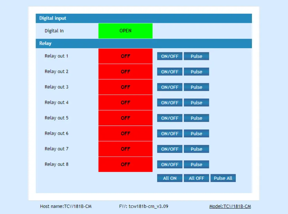 The “Monitoring” page provides information about the state of the relays and digital input.
The state of the relay can be changed by appropriate “ON/OFF” button. To change the state of the relay for a specified period, the “Pulse” button should be pressed. Duration of the pulse is specified for every single relay in “Pulse Duration” field of “I/O Setup” page.
Three buttons are located on the bottom of the page:
- “All ON” – click on this button will turn all relays ON
- “All OFF” – click on this button will turn all relays OFF
- “Pulse All” – click on this button will change the states of all relay outputs for a time, specified in “Pulse Duration” field of “I/O Setup” page.
Digital input can be used for monitoring the state of discrete devices – motion sensor, door contact, relay contact, alarm output etc. The digital input is not galvanic isolated.
Digital input is sampled every 30mS. The change of input status is considered valid if the same value is read in seven consecutive samples. 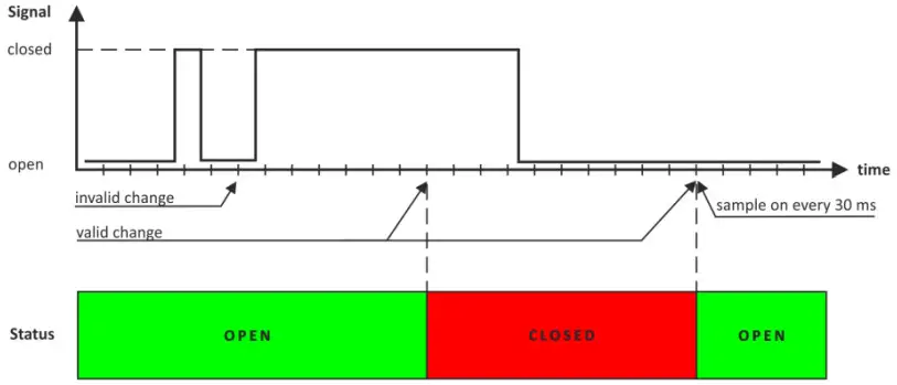 8.3 Network Setup page
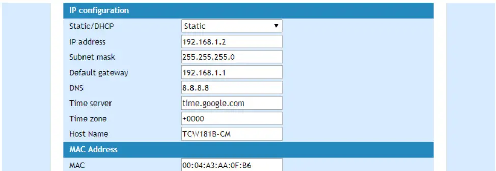
The Network parameters are set on this page.
For “IP configuration” and “MAC address” section, the following parameters can be changed:
- IP configuration – IP Address can be static or dynamic (DHCP server should be present in the network);
- IP address, Subnet mask, Default gateway – these fields are active if the IP address is static;
- DNS – this field is mandatory if domain names are used instead of IP addresses. By default DNS has the same IP address as Default gateway;
- Time Server and Time Zone – these fields are not mandatory, they are used when email must be sent;
- Host Name – up to 16 1-byte UTF-8 symbols, it appears as a “Subject” in sent e-mails;
- MAC – device MAC address.
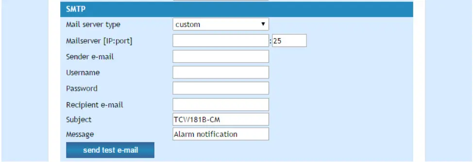
 The good practice is to change the default IP address of the controller immediately after first power-on. This will avoid collisions if many devices are used on the same network. It may be necessary to clear the apache, each time you connect a new device to the network. This is done by typing arid in the command prompt of window computer. To use e-mail alerts following fields should be completed:
- Mail server type – either “custom” or “tcw gateway”.
“Custom” – public or private mail server without SSL should be used.
Important! TCW181B-CM does not support Secure Socket Layer (SSL);
“Tcw gateway” – a dedicated mail server is used.
Important! The service is free and not guaranteed. - Mail server [IP: port] – domain or IP address and port of SMTP mail server;
- Sender E-mail – sender e-mail;
- Username and Password – authentication details for mail server;
- Mail to – recipient e-mail;
- Subject – e-mail subject;
- Message – e-mail body.
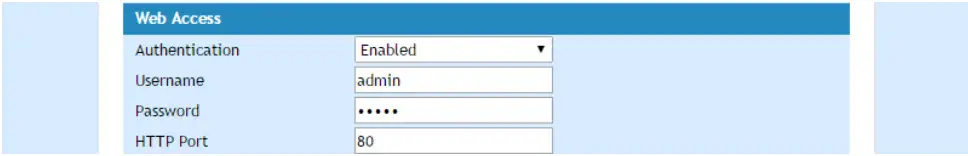
 Username and password for WEB access to TCW181B-CM can be changed in the Web Access section. Setting the authentication to “disabled” will provide access to monitoring page without entering username and password. The HTTP port can be changed also in this section.
 This section enables access to XML/HTTP API. Detailed information can be found in chapter “XML and HTTP API commands”.
8.4 SNMP Setup page
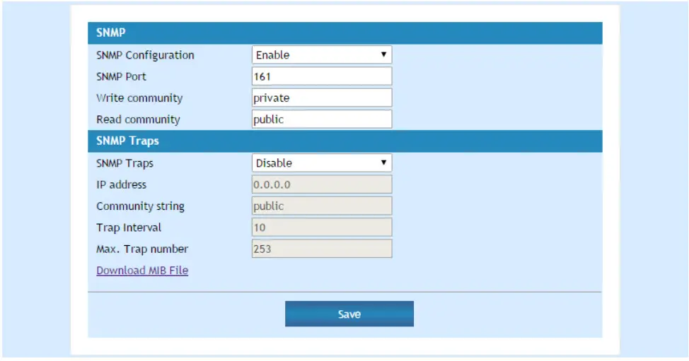
TCW181B-CM supports SNMP v.1 that enables trap delivery to an SNMP management application. This enables the device to be part of large monitoring and control networks. The possible settings for “SNMP” section are:
- SNMP Configuration – enable/disable SNMP;
- SNMP Port – SNMP port can be changed. By default port 161 is used;
- Write community – performs client authentication;
- Read community – performs client authentication;
- SNMP Traps – enable/disable SNMP trap messages;
- IP address – IP address of the receiving host
- Community string – performs client authentication
- Trap Interval – time interval in seconds for SNMP trap messages;
- Max. Traps number – the maximum number of SNMP trap messages sent if trap condition is present
 SNMP traps are sent if:
- event occurs (status change) on Digital Input;
- restart condition.
8.5 I/O Setup page
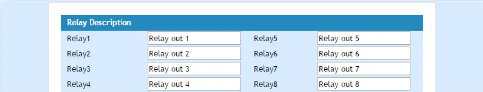
The following parameters can be set for the relays:
- Description – up to eleven bytes UTF-8 characters, less with special symbols;

- Pulse Duration – time for relay activation after “Pulse” command. There are separate settings for every relay. The pulse period can be set between 0.1 and 253 seconds.

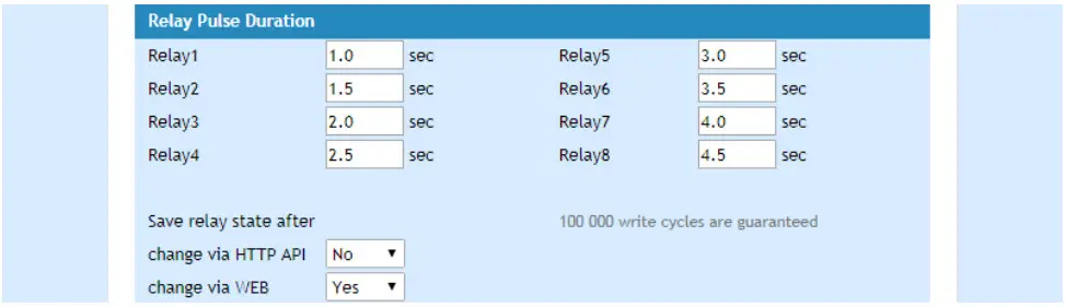
By default, relay state changes via the WEB interface are memorized in non-volatile memory. After the power on, the relay goes in its last state, before the power down.
If the “Save relay state after change via WEB” is No, after power on the relay is always OFF.
By default, relay state changes via the HTTP API aren’t saved and after power on the relay is always OFF.
The guaranteed write cycles (every change saving doesn’t matter via HTTP API or WEB) are 100000.
For the digital input following parameters can be set:
- Alert email – what to be done if there is a change in the status of digital input;
- Description – personal description for digital input, maximum eleven 1-byte UTF-8 characters, less with special symbols, can be used.
 Important! It is necessary to set SMTP settings on “Network Setup” page, to successfully send e-mail messages.
Automatic monitoring page refresh interval can be set from 1 to 253 second.
Remote control application example
The controlled device is connected in series with the relay contacts.
The user can operate TCW181B-CM using either a WEB browser or SNMP application. The relays can be managed independently of each other.
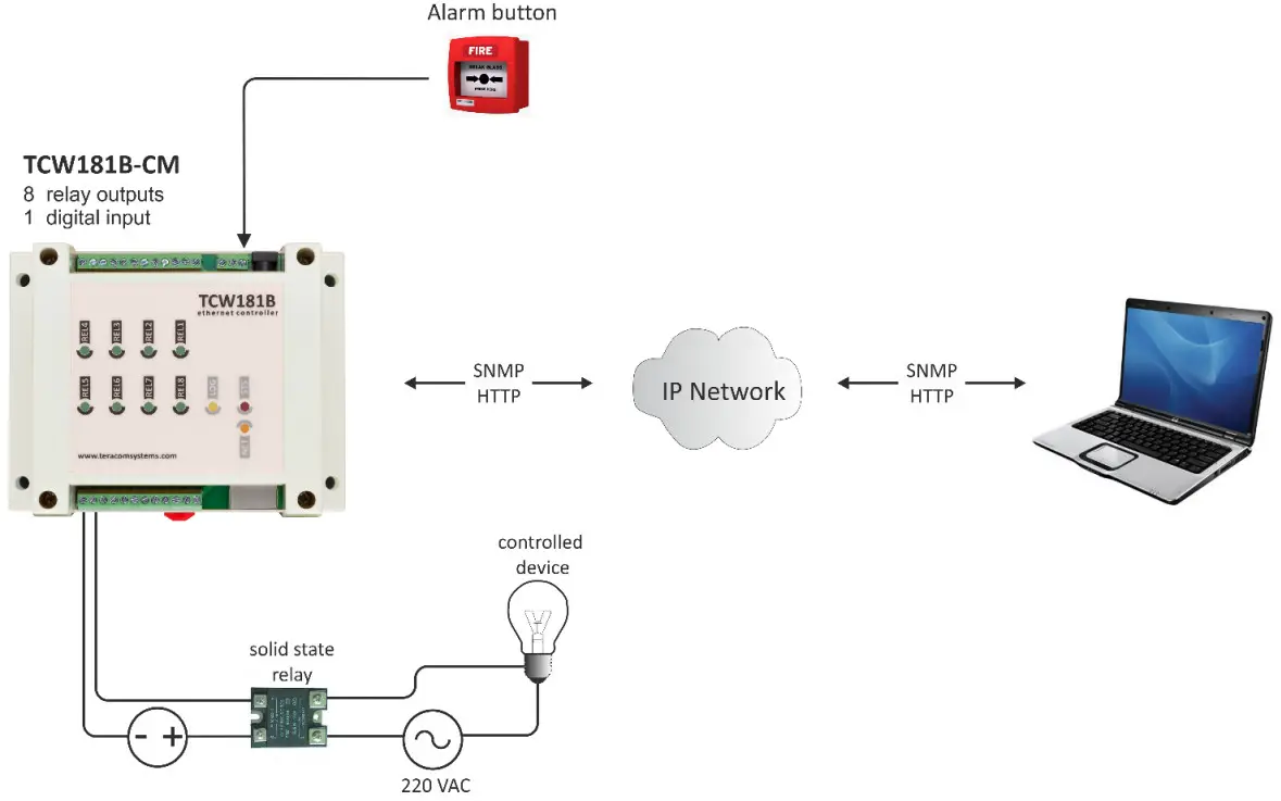 The above example is included solely for illustrative purposes. Because of the many variables and requirements associated with any particular installation, Teracom Ltd. cannot assume responsibility or liability for actual use based on the example.
Control and monitoring using SNMP
TCW181B-CM can be configured and monitored through SNMP (Simple Network Management Protocol). This could be done using every SNMPv.1 compatible program. Parameters that can be changed, are grouped according to their functions in the tables below. To obtain a valid OID number it is necessary to replace the “x” symbol with ”1.3.6.1.4.1.38783”. To save the changes configuration Saved (OID x.6.0) should be set to “1”.
10.1 Product
| OID | Name | Access | Description | Syntax |
| x.1.1.0 | Name | read-only | Device name | String |
| x.1.2.0 | Version | read-only | Software version | String |
| x.1.3.0 | Date | read-only | Release date | String |
10.2 SNMP Setup
| OID | Name | Access | Description | Syntax |
| x.2.1.0 | trap Enabled | read-write | TRAP messages enable/disable | INTEGER { no(0), yes(1) } |
| x.2.2.0 | trap Receiver IP Address | read-write | TRAP messages receiver address | IP Address |
| x.2.3.0 | trap Community | read-write | TRAP community | String (SIZE (0..13)) |
10.3 Monitor and control
| OID | Name | Access | Description | Syntax |
| x.3.1.0 | digital Input | read-only | Digital input state | INTEGER { closed(0), open(1) } |
| x.3.2.0 | relay1 | read-write | Relay 1 state | INTEGER { off(0), on(1) } |
| x.3.3.0 | relay2 | read-write | Relay 2 state | INTEGER { off(0), on(1) } |
| x.3.4.0 | relay3 | read-write | Relay 3 state | INTEGER { off(0), on(1) } |
| x.3.5.0 | relay4 | read-write | Relay 4 state | INTEGER { off(0), on(1) } |
| x.3.6.0 | relay5 | read-write | Relay 5 state | INTEGER { off(0), on(1) } |
| x.3.7.0 | relay6 | read-write | Relay 6 state | INTEGER { off(0), on(1) } |
| x.3.8.0 | relay7 | read-write | Relay 7 state | INTEGER { off(0), on(1) } |
| x.3.9.0 | relay8 | read-write | Relay 8 state | INTEGER { off(0), on(1) } |
| x.3.10.0 | pulse1 | read-write | Relay 1 pulse state | INTEGER { off(0), on(1) } |
| x.3.11.0 | pulse2 | read-write | Relay 2 pulse state | INTEGER { off(0), on(1) } |
| x.3.12.0 | pulse3 | read-write | Relay 3 pulse state | INTEGER { off(0), on(1) } |
| x.3.13.0 | pulse4 | read-write | Relay 4 pulse state | INTEGER { off(0), on(1) } |
| x.3.14.0 | pulse5 | read-write | Relay 5 pulse state | INTEGER { off(0), on(1) } |
| x.3.15.0 | pulse6 | read-write | Relay 6 pulse state | INTEGER { off(0), on(1) } |
| x.3.16.0 | pulse7 | read-write | Relay 7 pulse state | INTEGER { off(0), on(1) } |
| x.3.17.0 | pulse8 | read-write | Relay 8 pulse state | INTEGER { off(0), on(1) } |
| x.3.18.0 | all On | read-write | Set all relays On | INTEGER { off(0), on(1) } |
| x.3.19.0 | all Off | read-write | Set all relays Off | INTEGER { off(0), on(1) } |
| x.3.20.0 | all Pulse | read-write | Pulse all relays | INTEGER { off(0), on(1) } |
10.4 Network
| OID | Name | Access | Description | Syntax |
| x.4.1.0 | device IP Address | read-write | Device IP address | IP Address |
| x.4.2.0 | subnet Mask | read-write | Subnet Mask | IP Address |
| x.4.3.0 | gateway | read-write | Gateway | IP Address |
| x.4.4.0 | device MAC Address | read-write | Device MAC Address | OCTET STRING (SIZE(6)) |
| x.4.5.0 | dhcp Config | read-write | DHCP ON/OFF | INTEGER { off(0), on(1) } |
10.5 I/O Setup
| OID | Name | Access | Description | Syntax |
| x.5.1.0 | relay1PulseDuration | read-write | Pulse duration of relay1 | INTEGER (0..253) |
| x.5.2.0 | relay2PulseDuration | read-write | Pulse duration of relay2 | INTEGER (0..253) |
| x.5.3.0 | relay3PulseDuration | read-write | Pulse duration of relay3 | INTEGER (0..253) |
| x.5.4.0 | relay4PulseDuration | read-write | Pulse duration of relay4 | INTEGER (0..253) |
| x.5.5.0 | relay5PulseDuration | read-write | Pulse duration of relay5 | INTEGER (0..253) |
| x.5.6.0 | relay6PulseDuration | read-write | Pulse duration of relay6 | INTEGER (0..253) |
| x.5.7.0 | relay7PulseDuration | read-write | Pulse duration of relay7 | INTEGER (0..253) |
| x.5.8.0 | relay8PulseDuration | read-write | Pulse duration of relay8 | INTEGER (0..253) |
| x.5.9.0 | relay1description | read-write | Relay 1 description | String (SIZE (0..11)) |
| x.5.10.0 | relay2description | read-write | Relay 2 description | String (SIZE (0..11)) |
| x.5.11.0 | relay3description | read-write | Relay 3 description | String (SIZE (0..11)) |
| x.5.12.0 | relay4description | read-write | Relay 4 description | String (SIZE (0..11)) |
| x.5.13.0 | relay5description | read-write | Relay 5 description | String (SIZE (0..11)) |
| x.5.14.0 | relay6description | read-write | Relay 6 description | String (SIZE (0..11)) |
| x.5.15.0 | relay7description | read-write | Relay 7 description | String (SIZE (0..11)) |
| x.5.16.0 | relay8description | read-write | Relay 8 description | String (SIZE (0..11)) |
| x.5.17.0 | digital Input Action | read-write | Digital Input Action condition | INTEGER { no Action (0), mail If Open To Closed(1), mail If Closed To Open(2) } |
| x.5.18.0 | digital Input To | read-write | Digital Input event receiver’s e-mail address | String (SIZE (0..38)) |
| x.5.19.0 | digital Input Subject | read-write | Digital Input event e-mail’s subject | String (SIZE (0..11)) |
| x.5.20.0 | digital Input Body | read-write | Digital Input event e-mail’s body | String (SIZE (0..22)) |
| x.5.21.0 | relay1PulseDurationMs | read-write | Pulse duration x 100 in milliseconds of relay1 | INTEGER (0..9) |
| x.5.22.0 | relay2PulseDurationMs | read-write | Pulse duration x 100 in milliseconds of relay2 | INTEGER (0..9) |
| x.5.23.0 | relay3PulseDurationMs | read-write | Pulse duration x 100 in milliseconds of relay3 | INTEGER (0..9) |
| x.5.24.0 | relay4PulseDurationMs | read-write | Pulse duration x 100 in milliseconds of relay4 | INTEGER (0..9) |
| x.5.25.0 | relay5PulseDurationMs | read-write | Pulse duration x 100 in milliseconds of relay5 | INTEGER (0..9) |
| x.5.26.0 | relay6PulseDurationMs | read-write | Pulse duration x 100 in milliseconds of relay6 | INTEGER (0..9) |
| x.5.27.0 | relay7PulseDurationMs | read-write | Pulse duration x 100 in milliseconds of relay7 | INTEGER (0..9) |
| x.5.28.0 | relay8PulseDurationMs | read-write | Pulse duration x 100 in milliseconds of relay8 | INTEGER (0..9) |
| x.5.29.0 | digital Input Description | read-write | Digital input description | String (SIZE (0..11)) |
| x.6.0 | configuration Saved | read-write | Configuration save status SAVED/UNSAVED | INTEGER { unsaved(0), saved(1) } |
| x.7.0 | restart Device | read-write | Restart Device | INTEGER { cancel(0), restart(1) } |
XML and HTTP API commands
XML is often preferred choice when it comes to M2M communication and system integration. The monitored values are transmitted in status.xml file that can be easily processed by software applications.
Below is the structure of the status.xml file:
<Monitor>
<Device>TCW181B-CM</Device>
<ID>00:04:A3:AA:0F:B6</ID>
<Hostname>TCW181B-CM</Hostname>
<FW>3.09</FW>
<Digital Input Description>Digital In</Digital Input Description>
<Digital Input>OPEN</Digital Input>
<Din Alarm>0</Din Alarm>
<Relay1Description>Relay out 1</Relay1Description>
<Relay1>OFF</Relay1>
<pw1>1.0</pw1>
<Relay2Description>Relay out 2</Relay2Description>
<Relay2>OFF</Relay2>
<pw2>1.5</pw2>
<Relay3Description>Relay out 3</Relay3Description>
<Relay3>OFF</Relay3>
<pw3>2.0</pw3>
<Relay4Description>Relay out 4</Relay4Description>
<Relay4>OFF</Relay4>
<pw4>2.5</pw4>
<Relay5Description>Relay out 5</Relay5Description>
<Relay5>OFF</Relay5>
<pw5>3.0</pw5>
<Relay6Description>Relay out 6</Relay6Description>
<Relay6>OFF</Relay6>
<pw6>3.5</pw6>
<Relay7Description>Relay out 7</Relay7Description>
<Relay7>OFF</Relay7>
<pw7>4.0</pw7>
<Relay8Description>Relay out 8</Relay8Description>
<Relay8>OFF</Relay8>
<pw8>4.5</pw8>
</Monitor>
If XML/HTTP API authentication is enabled, basic access authentication is required to access the status.xml file. The format of the command is shown in the table below:
| XML/HTTP API authentication | Format |
| enabled | http://device.ip.address/status.xml?a= uuuu: pppp |
| disabled | http://device.ip.address/status.xml |
Where uuuu is username and pppp is password. Both parameters are unencrypted.
The relay outputs can be controlled by sending HTTP commands:
| Command | Description |
| http://device.ip.address/status.xml?rX=1 | Turn Relay X ON |
| http://device.ip.address/status.xml?rX=0 | Turn Relay X OFF |
| http://device.ip.address/status.xml?tgX=1 | Toggle Relay X state |
| http://device.ip.address/status.xml?plX=1 | Pulse Relay X |
| http://device.ip.address/status.xml?rX=1&rY=1 | Turn both relays X and Y ON |
| http://device.ip.address/status.xml?rX=0&rY=0 | Turn both relays X and Y OFF |
Where X and Y are the number of the corresponding relay output (1 to 8).
If XML/HTTP API authentication is enabled, basic access authentication is required to send HTTP commands. The format of the commands is shown in the table below (user name=admin, pass=admin):
| XML/HTTP API authentication | Format |
| enabled | http://device.ip.address/status.xml?a=admin:admin&r1=1 |
| disabled | http://device.ip.address/status.xml?r1=1 |
Factory default settings
TCW181B-CM can be restored to its original factory default settings, following the steps below:
- Turn off the power supply;
- Press and hold the RESET button then turn on the power supply;
- After turning the power supply release the RESET button. The LED’s STS and LOG will flash 14 times after that only the STS LED will continue to blink. The controller is restored to its default settings.
 The factory default settings are:
| User Name (Admin) | admin |
| Password (Admin) | admin |
| IP Address | 192.168.1.2 |
| Subnet Mask | 255.255.255.0 |
| Default Gateway | 192.168.1.1 |
| SNMP Configuration | disabled |
| read Community | public |
| write Community | private |
Firmware update
TCW181B-CM supports remote firmware update. To update the device follow the steps below:
- Go to www.teracomsystems.com and download the latest firmware version from TCW181B-CM product page;
- Go to the device Login page, enter username and password and press the “Login” button;
- Go to the “Update” menu, select the update .cod file and press “upload” button;
- After the firmware update is completed, you will be forwarded to the device Login page.
Attention! Don’t turn off the power supply during the update. Turning off the power supply will damage the device.
Overvoltage protection
If the power supply voltage goes higher than 16VDC, the overvoltage protection is activated.
In this mode there is a warning message on the monitoring page, the relays are inactive (OFF) and the status of LED’s is:
- Sts (red) – turns ON;
- Log (yellow) – flashes fast.
Environment information
This equipment is intended for use in a Pollution Degree 2 environment, at altitudes up to 2000 meters.
When the controller is a part of a system, the other elements of the system shall comply with the EMC requirements and shall be intended for use in the same ambient conditions.
Safety
This device must not be used for medical, life-saving purposes or for any purpose where its failure could cause serious injury or the loss of life.
To reduce the risk of fire, only flexible stranded wire, with cross-section 0.5mm² or larger for wiring of digital and analog inputs and relay output of the device should be used.
To avoid electric shock and fire hazard, do not expose this product to liquids, rain, or moisture.
Objects filled with liquids, such as vases, should not be placed on this device.
There is a risk of overheating (damage) of the controller if recommended free spaces to adjacent devices are not ensured. The joint part with external component shall have space for attachment/removal of the cable after installation.
Teracom does not guarantee a successful operation of the product if the product was used under conditions deviating from the product specifications.
To ensure that the device works correctly follow the steps below:
- ensure that the devices are installed correctly, refer this user manual;
- log into the devices via a browser;
- make proper setup;
- set up the digital input to work in “dry contact” mode;
- short the “DI” and “GND”;
- Switch on “Monitoring page” of WEB interface – proper value for digital input should be displayed at the same time Sts led should flashes;
- When you push the button “All On”, all relays should be activated and all relay’s status LED’s should be constantly ON.
If the equipment is used in a manner not specified by the manufacturer, the protection provided by the equipment may be impaired.
Maintenance
Upon completion of any service or repairs to the device or once per year, a safety check must be performed to determine that this product is in proper operating condition.
Clean the device only with a dry cloth. Do not use a liquid cleaner or an aerosol cleaner. Do not use a magnetic/static cleaning device (dust remover) or any kind of abrasive materials to clean the device.
 |  |
TCW181B-CM_R4.10 – October 2022


