![]()
Installation Instructions
Model NIM-1W Network Interface Module
NETWORK INTERFACE APPLICATIONS
OPERATION
The Model NIM-1W from Siemens Industry, Inc., provides a new communication path for the following uses:
- as an XNET networking interface
- as an HNET connection to NCC WAN
- as a connection to Foreign Systems
- as a connection to Air Sampling detectors
When used as an XNET networking interface the NIM-1W allows for the connection of up to 63 MXL and/or XLS Systems. On an XNET network the NIM1W also supports monitor and control functionality by Siemens products, such as NCC and Desigo CC.
Output logic between MXL panels is done using CSG-M programming. CSG-M versions 6.01 and higher include options for networked MXL Systems. Each MXL System is assigned a panel number. This panel number allows interactive programming between panels using CSG-M.
The NIM-1W supports both Style 4 and Style 7 connection. In the event of an NIM-1W communication failure, each MXL System continues to operate as a standalone panel.
The NIM-1W can also be configured as an RS-485 two wire interface to foreign systems. NIM-1W RS485 only supports Style 4 wiring. Via the add-on modem card NIM-1M, NIM-1W can also be configured for modem connection. This operation is called FSI (Foreign System Interface). The FSI responds to a protocol and gathers information about the MXL status. The interface supports both single MXL Systems and networked systems. Typical use of this interface is between the MXL and building management
systems.
Use the CSG-M to enable the functions accessed by the foreign system. If the foreign system is UL 864 listed with the MXL, the interface can also be enabled to support control of the MXL including the commands to acknowledge, silence, and reset.
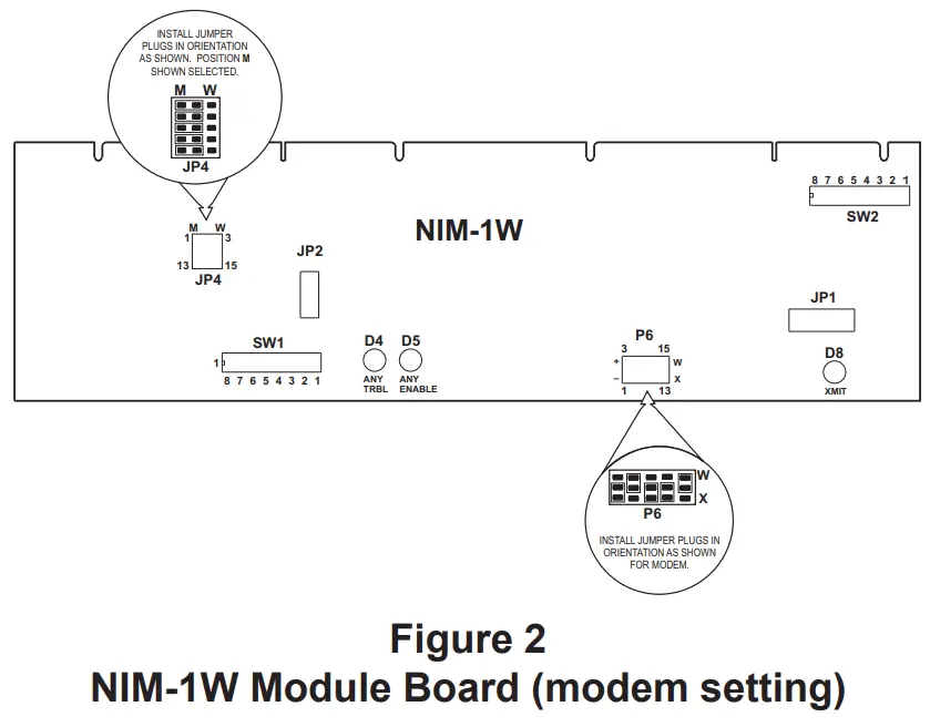
TABLE 1
NETWORK ADDRESS PROGRAMMING (SW1)
| ADDR | 87654321 | ADDR | 87654321 | ADDR | 87654321 | ADDR | 87654321 |
| 000 | ILLEGAL | 064 | OXOOOOOO | 128 | XOOOOOOO | 192 | XXOOOOOO |
| 001 | ILLEGAL | 065 | OXOOOOOX | 129 | XOOOOOOX | 193 | XXOOOOOX |
| 002 | ILLEGAL | 066 | OXOOOOXO | 130 | XOOOOOXO | 194 | XXOOOOXO |
| 003 | OOOOOOXX | 067 | OXOOOOXX | 131 | XOOOOOXX | 195 | XXOOOOXX |
| 004 | OOOOOXOO | 068 | OXOOOXOO | 132 | XOOOOXOO | 196 | XXOOOXOO |
| 005 | OOOOOXOX | 069 | OXOOOXOX | 133 | XOOOOXOX | 197 | XXOOOXOX |
| 006 | OOOOOXXO | 070 | OXOOOXXO | 134 | XOOOOXXO | 198 | XXOOOXXO |
| 007 | OOOOOXXX | 071 | OXOOOXXX | 135 | XOOOOXXX | 199 | XXOOOXXX |
| 008 | OOOOXOOO | 072 | OXOOXOOO | 136 | XOOOXOOO | 200 | XXOOXOOO |
| 009 | OOOOXOOX | 073 | OXOOXOOX | 137 | XOOOXOOX | 201 | XXOOXOOX |
| 010 | OOOOXOXO | 074 | OXOOXOXO | 138 | XOOOXOXO | 202 | XXOOXOXO |
| 011 | OOOOXOXX | 075 | OXOOXOXX | 139 | XOOOXOXX | 203 | XXOOXOXX |
| 012 | OOOOXXOO | 076 | OXOOXXOO | 140 | XOOOXXOO | 204 | XXOOXXOO |
| 013 | OOOOXXOX | 077 | OXOOXXOX | 141 | XOOOXXOX | 205 | XXOOXXOX |
| 014 | OOOOXXXO | 078 | OXOOXXXO | 142 | XOOOXXXO | 206 | XXOOXXXO |
| 015 | OOOOXXXX | 079 | OXOOXXXX | 143 | XOOOXXXX | 207 | XXOOXXXX |
| 016 | OOOXOOOO | 080 | OXOXOOOO | 144 | XOOXOOOO | 208 | XXOXOOOO |
| 017 | OOOXOOOX | 081 | OXOXOOOX | 145 | XOOXOOOX | 209 | XXOXOOOX |
| 018 | OOOXOOXO | 082 | OXOXOOXO | 146 | XOOXOOXO | 210 | XXOXOOXO |
| 019 | OOOXOOXX | 083 | OXOXOOXX | 147 | XOOXOOXX | 211 | XXOXOOXX |
| 020 | OOOXOXOO | 084 | OXOXOXOO | 148 | XOOXOXOO | 212 | XXOXOXOO |
| 021 | OOOXOXOX | 085 | OXOXOXOX | 149 | XOOXOXOX | 213 | XXOXOXOX |
| 022 | OOOXOXXO | 086 | OXOXOXXO | 150 | XOOXOXXO | 214 | XXOXOXXO |
| 023 | OOOXOXXX | 087 | OXOXOXXX | 151 | XOOXOXXX | 215 | XXOXOXXX |
| 024 | OOOXXOOO | 088 | OXOXXOOO | 152 | XOOXXOOO | 216 | XXOXXOOO |
| 025 | OOOXXOOX | 089 | OXOXXOOX | 153 | XOOXXOOX | 217 | XXOXXOOX |
| 026 | OOOXXOXO | 090 | OXOXXOXO | 154 | XOOXXOXO | 218 | XXOXXOXO |
| 027 | OOOXXOXX | 091 | OXOXXOXX | 155 | XOOXXOXX | 219 | XXOXXOXX |
| 028 | OOOXXXOO | 092 | OXOXXXOO | 156 | XOOXXXOO | 220 | XXOXXXOO |
| 029 | OOOXXXOX | 093 | OXOXXXOX | 157 | XOOXXXOX | 221 | XXOXXXOX |
| 030 | OOOXXXXO | 094 | OXOXXXXO | 158 | XOOXXXXO | 222 | XXOXXXXO |
| 031 | OOOXXXXX | 095 | OXOXXXXX | 159 | XOOXXXXX | 223 | XXOXXXXX |
| 032 | OOXOOOOO | 096 | OXXOOOOO | 160 | XOXOOOOO | 224 | XXXOOOOO |
| 033 | OOXOOOOX | 097 | OXXOOOOX | 161 | XOXOOOOX | 225 | XXXOOOOX |
| 034 | OOXOOOXO | 098 | OXXOOOXO | 162 | XOXOOOXO | 226 | XXXOOOXO |
| 035 | OOXOOOXX | 099 | OXXOOOXX | 163 | XOXOOOXX | 227 | XXXOOOXX |
| 036 | OOXOOXOO | 100 | OXXOOXOO | 164 | XOXOOXOO | 228 | XXXOOXOO |
| 037 | OOXOOXOX | 101 | OXXOOXOX | 165 | XOXOOXOX | 229 | XXXOOXOX |
| 038 | OOXOOXXO | 102 | OXXOOXXO | 166 | XOXOOXXO | 230 | XXXOOXXO |
| 039 | OOXOOXXX | 103 | OXXOOXXX | 167 | XOXOOXXX | 231 | XXXOOXXX |
| 040 | OOXOXOOO | 104 | OXXOXOOO | 168 | XOXOXOOO | 232 | XXXOXOOO |
| 041 | OOXOXOOX | 105 | OXXOXOOX | 169 | XOXOXOOX | 233 | XXXOXOOX |
| 042 | OOXOXOXO | 106 | OXXOXOXO | 170 | XOXOXOXO | 234 | XXXOXOXO |
| 043 | OOXOXOXX | 107 | OXXOXOXX | 171 | XOXOXOXX | 235 | XXXOXOXX |
| 044 | OOXOXXOO | 108 | OXXOXXOO | 172 | XOXOXXOO | 236 | XXXOXXOO |
| 045 | OOXOXXOX | 109 | OXXOXXOX | 173 | XOXOXXOX | 237 | XXXOXXOX |
| 046 | OOXOXXXO | 110 | OXXOXXXO | 174 | XOXOXXXO | 238 | XXXOXXXO |
| 047 | OOXOXXXX | 111 | OXXOXXXX | 175 | XOXOXXXX | 239 | XXXOXXXX |
| 048 | OOXXOOOO | 112 | OXXXOOOO | 176 | XOXXOOOO | 240 | XXXXOOOO |
| 049 | OOXXOOOX | 113 | OXXXOOOX | 177 | XOXXOOOX | 241 | XXXXOOOX |
| 050 | OOXXOOXO | 114 | OXXXOOXO | 178 | XOXXOOXO | 242 | XXXXOOXO |
| 051 | OOXXOOXX | 115 | OXXXOOXX | 179 | XOXXOOXX | 243 | XXXXOOXX |
| 052 | OOXXOXOO | 116 | OXXXOXOO | 180 | XOXXOXOO | 244 | XXXXOXOO |
| 053 | OOXXOXOX | 117 | OXXXOXOX | 181 | XOXXOXOX | 245 | XXXXOXOX |
| 054 | OOXXOXXO | 118 | OXXXOXXO | 182 | XOXXOXXO | 246 | XXXXOXXO |
| 055 | OOXXOXXX | 119 | OXXXOXXX | 183 | XOXXOXXX | 247 | XXXXOXXX |
| 056 | OOXXXOOO | 120 | OXXXXOOO | 184 | XOXXXOOO | 248 | ILLEGAL |
| 057 | OOXXXOOX | 121 | OXXXXOOX | 185 | XOXXXOOX | 249 | ILLEGAL |
| 058 | OOXXXOXO | 122 | OXXXXOXO | 186 | XOXXXOXO | 250 | ILLEGAL |
| 059 | OOXXXOXX | 123 | OXXXXOXX | 187 | XOXXXOXX | 251 | ILLEGAL |
| 060 | OOXXXXOO | 124 | OXXXXXOO | 188 | XOXXXXOO | 252 | ILLEGAL |
| 061 | OOXXXXOX | 125 | OXXXXXOX | 189 | XOXXXXOX | 253 | ILLEGAL |
| 062 | OOXXXXXO | 126 | OXXXXXXO | 190 | XOXXXXXO | 254 | ILLEGAL |
| 063 | OOXXXXXX | 127 | OXXXXXXX | 191 | XOXXXXXX | 255 | ILLEGAL |
O = OPEN (or OFF) X = CLOSED ( or ON)
TABLE 2
PANEL NUMBER PROGRAMMING (SW2)
| ADDR | 8 7 6 5 4 3 2 1 | ADDR | 8 7 6 5 4 3 2 1 | ADDR | 8 7 6 5 4 3 2 1 | ADDR | 8 7 6 5 4 3 2 1 |
| 000 | ROOOOOOO | 016 | SOOXOOOO | 032 | SOXOOOOO | 048 | SOXXOOOO |
| 001 | SOOOOOOX | 017 | SOOXOOOX | 033 | SOXOOOOX | 049 | SOXXOOOX |
| 002 | SOOOOOXO | 018 | SOOXOOXO | 034 | SOXOOOXO | 050 | SOXXOOXO |
| 003 | SOOOOOXX | 019 | SOOXOOXX | 035 | SOXOOOXX | 051 | SOXXOOXX |
| 004 | SOOOOXOO | 020 | SOOXOXOO | 036 | SOXOOXOO | 052 | SOXXOXOO |
| 005 | SOOOOXOX | 021 | SOOXOXOX | 037 | SOXOOXOX | 053 | SOXXOXOX |
| 006 | SOOOOXXO | 022 | SOOXOXXO | 038 | SOXOOXXO | 054 | SOXXOXXO |
| 007 | SOOOOXXX | 023 | SOOXOXXX | 039 | SOXOOXXX | 055 | SOXXOXXX |
| 008 | SOOOXOOO | 024 | SOOXXOOO | 040 | SOXOXOOO | 056 | SOXXXOOO |
| 009 | SOOOXOOX | 025 | SOOXXOOX | 041 | SOXOXOOX | 057 | SOXXXOOX |
| 010 | SOOOXOXO | 026 | SOOXXOXO | 042 | SOXOXOXO | 058 | SOXXXOXO |
| 011 | SOOOXOXX | 027 | SOOXXOXX | 043 | SOXOXOXX | 059 | SOXXXOXX |
| 012 | SOOOXXOO | 028 | SOOXXXOO | 044 | SOXOXXOO | 060 | SOXXXXOO |
| 013 | SOOOXXOX | 029 | SOOXXXOX | 045 | SOXOXXOX | 061 | SOXXXXOX |
| 014 | SOOOXXXO | 030 | SOOXXXXO | 046 | SOXOXXXO | 062 | SOXXXXXO |
| 015 | SOOOXXXX | 031 | SOOXXXXX | 047 | SOXOXXXX | 063 | SOXXXXXX |
| — | ————— | — | ————— | — | ————– | 064 | SXOOOOOO |
| S = Closed selects Style 7 S = Open selects Style 4 | O = Open or OFF X = Closed or ON | R = Closed selects AnaLASER R = Open selects FSI | |||||
NOTE:
To open a dipswitch, press down on the side of the dipswitch marked OPEN.
To close a dipswitch, press down on the side of the dipswitch opposite the side marked OPEN.
To open a slide switch, push the slide to the side opposite the side marked ON.
To close a slide switch, push the slide to the side marked ON.
The NIM-1W also provides for the connection of up to 31 Air Sampling detectors. The MXL supports individual programming and monitoring of the Air Sampling devices. Each detector can be uniquely programmed from the MKB menu or by using CSG-M. All three alarm levels (PreAlarm 1, PreAlarm 2, and Alarm) are supported.
NOTE: When the NIM-1W is configured as an Air Sampling interface, it cannot support either MXL networking or the FSI. If these functions are required, additional NIM-1Ws must be used.
For additional information on the MXL/MXLV System, refer to the MXL/MXLV Manual, P/N 315-092036.
INSTALLATION
Remove all system power before installation, first battery and then AC. (To power up, connect the AC first, then the battery.)
The NIM-1W installs into the MXL optional MOM-4/2 card cage where it occupies one full width slot. The NIM-1W can be installed in either of the full slots of the MOM-4/2. The slot determines if the wiring is connected to TB3 or TB4 of the MOM-4/2.
Setting the Switches
Set all switches, configuration jumpers, and connection cables before installing the NIM-1W into the MOM-4.
Use switch SW1 to set the MXL network address. Set this switch according to the address where the NIM-1W is installed in the MXL’s network map. Refer to the CSG-M configuration printout for the address of the module. See Table 1 for settings.
Use switch SW2 to set either the panel number for networked systems or to select FSI or Air Sampling operation. Refer to Table 2 for panel settings, Table 3 for FSI settings, and Table 4 for Air Sampling settings.
- When installing the NIM-1W in a networked system, set the panel number to agree with the panel number for the NIM-1W assigned to the MXL System in CSG-M.
- Switch position 8 selects Style 4 or Style 7 operation for the NIM-1W network.
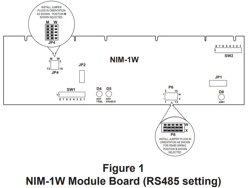
- Set jumper plugs on JP4 to the “M” position.
- Set jumper plugs on P6 to the “X” position (Figure 1) if using NIM-1W for RS-485 interface. Set jumper plugs on P6 as shown in Figure 2 if using NIM-W for modem interface.
NOTES:
- 18 AWG minimum.
- 80 ohms maximum per pair.
- Use shielded twisted pair.
- Terminate the shield at MXL Panel 1 only.
- Power limited to NFPA 70 per NEC 760.
- Maximum voltage 8V peak to peak.
- Maximum current 150mA.
- For Style 4 omit all Network Pair B connections.
- CC-5 terminals 9-14 are not connected and can be used to tie shields together.
- Refer to Wiring Specification for MXL, MXL-IQ and MXLV Systems, P/N 315092772 revision 6 or higher, for additional wiring information.
5. When installing the NIM-1W for FSI operation, set the switch to all open (or OFF).
TABLE 3
FSI PROGRAMMING
| ADDR | 8 7 6 5 4 3 2 1 |
| FSI | OOOOOOOO |
| O = Open or OFF | |
6. When installing the NIM-1W for Air Sampling detection connection, set the switch as follows:
TABLE 3
AIR SAMPLING PROGRAMMING
| ADDR FSI | 8 7 6 5 4 3 2 1 |
| Air Sampling | XOOOOOOO |
| O = Open or OFF X = Closd or ON | |
After setting the switches, install the NIM-1W into the MOM-4/2 card cage. Make sure that the module is in the card guides and the card edge is firmly seated in the connectors on the MOM-4/2.
CAUTION
At all times handle all plug-in cards with extreme care. When inserting or removing a card, be sure the position of the card is kept at right angles to the MOM-4 board. Otherwise, the plug-in card can damage or displace other components.
ELECTRICAL CONNECTIONS
NIM-1W On An XNET Network
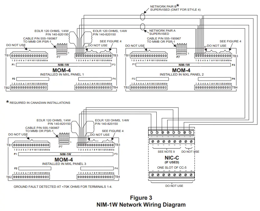
Figure 3 shows the wiring diagram for the NIM-1W on an XNET network. Up to 32 MXL and/or XLS Systems can be connected in the XNET network with an NIM-1W installed in each MXL System. For the highest level of fault protection, install the NIM-1W in the enclosure with the MMB, although this is not necessary. When connecting more than 32 MXL Systems, an REP-1 repeater, a D2300CPS or a D2325CPS is required. Refer to the REP-1 Installation Instructions, P/N 315-092686, the D2300CPS Installation Instructions, P/N 315-050018 or the D2325CPS Installation Instructions, P/N 315-050019, as applicable, for the wiring diagram.
The XNET network can be installed as either Style 4 or Style 7. Figure 3 shows which wires must be added to support Style 7. Style 7 is required in Canada. Each NIM-1W is shipped with two 120 ohm EOLRs— only two are required for each network pair. Install an EOLR at the ends of each network pair. Do not install an EOLR at each NIM-1W. (A simple rule of thumb for the NIM-1W: an EOLR must be installed where only a single wire lands on a screw terminal.)
Do not T-tap the network wiring. If T-tapping is required, use the REP-1 repeater. Refer to the REP-1 Installation Instructions, P/N 315-092686, the D2300CPS Installation Instructions, P/N 315-050018 or the D2325CPS Installation Instructions, P/N 315050019, as applicable, for the wiring diagram.
For Style 4 wiring, terminate the secondary network pair (terminals 3 and 4) on each NIM-1W with an EOLR.
Network Command Center (NCC/Desigo CC)
Figure 4 shows the wiring to the NCC/Desigo CC.
To connect the NCC/Desigo CC, observe the following restrictions:
- Give the NCC/Desigo CC a panel number. (This panel number is in addition to the panel number for the MXL System that the NCC/Desigo CC connects to.)
- The total number of panels in the XNET must not exceed 64, including the NCC/Desigo CC.
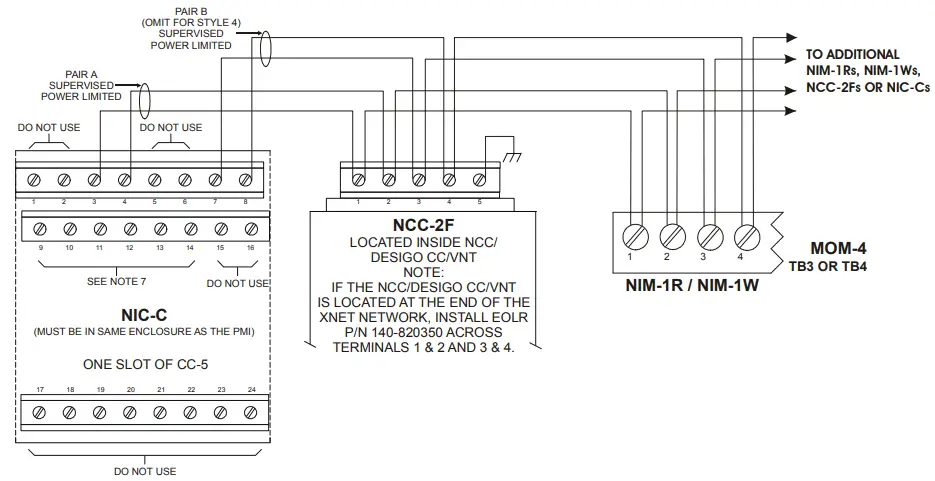
Figure 4
Connecting the NIM-1W to the NCC/Desigo CC and FireFinder-XLS
NOTES:
- No EOLR required for NIC-C.
- The screw terminals can accommodate one 12-24AWG or two 1624AWG.
- From the NCC-2F to NIM-1R, NIM-1W or NCC-2F: 80 Ohms max. per pair.
Unshielded twisted pair – .5μF line to line Shielded twisted pair – .3μF line to line, .4μF line to shield - From the NCC-2F to NIC-C:
2000 feet (33.8 ohms) max. per pair between CC-5s/CC-2s.
Unshielded twisted pair .25μF max. line to line Shielded twisted pair.15μF max. line to line.2μF max. line to shield - Use twisted pair or twisted shielded pair.
- Terminate shields at one end only.
- Power limited to NFPA 70 per NEC 760.
- CC-5 terminals 9 – 14 are not connected and can be used to tie shields together.
- Positive or negative ground fault detected at <10K ohms on pins 3-4, 7-8 of the NIC-C.
- Each pair independently supervised.
- Maximum voltage 8V P-P.
- Maximum current 75mA during message transmission.
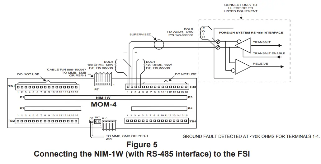
Foreign System Interface (FSI)
The FSI installs on TB3 or TB4, terminals 1 and 2, of the MOM-4/2 depending on where the NIM-1W is installed, as shown in Figure 5. Use one of the EOLRs provided with the NIM-1W on terminals 1 and 2. This properly terminates the FSI. Use the second EOLR on terminals 3 and 4. Never use terminals 3 and 4 to connect to the FSI. Refer to Figure 5 for the polarity of the FSI driver.
If multiple FSI connections are required, up to four NIM-1Ws may be installed in an individual MXL System. In networked systems each MXL can support up to four FSI ports. For networked systems, each FSI port must be configured as either local or global in the CSG-M. Local FSI ports display information only on the MXL System to which they are connected. Global FSI ports display all events in all MXL Systems. Refer to the CSG-M Manual, P/N 315-090381, for further information.
Connection via NIM-1W RS-485 Interface
NIM-W RS485 FSI connection should be wired Style 4 only. The recommended Serial Baud Rate when using NIM-1W RS485 FSI is 19200 bpm. P6 jumper position on the NIM-1W should be set for RS-485 configuration as shown in Figure 1. Refer to Figure 5 for wiring instructions.
NOTES:
- 18 AWG minimum.
- 80 ohms maximum per pair.
- Use shielded twisted pair.
- Terminate the shield at the NIM-1W enclosure only.
- Power limited to NFPA 70 per NEC 760.
- Maximum voltage 8V peak to peak.
- Maximum current 150mA.
- Refer to Wiring Specification for MXL, MXL-IQ and MXLV Systems, P/N 315-092772 revision 6 or higher, for additional wiring information.
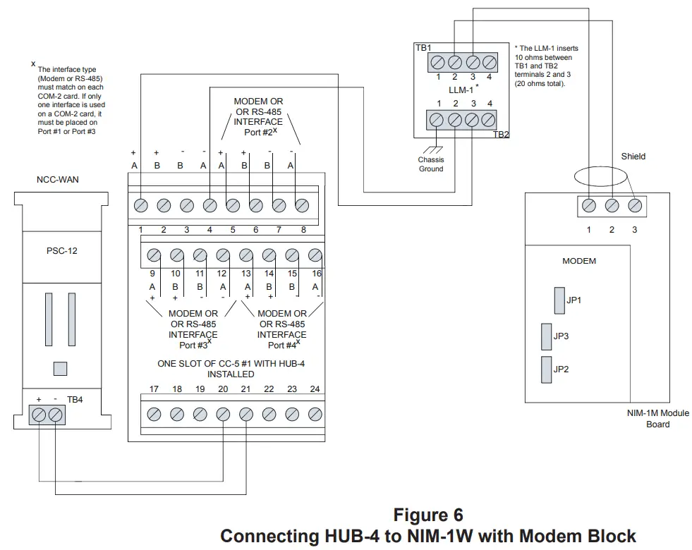
Connection via NIM-1W/NIM-1M Modem
NIM-1W/NIM-1M modem FSI connection should be wired Style 4 only. P6 jumper position on the NIM-1W should be set for Modem configuration as shown in Figure 2. The recommended Serial Baud Rate when using NIM-1W/NIM-1M Modem FSI is 19200 bpm. Refer to Figure 16 for wiring instructions.
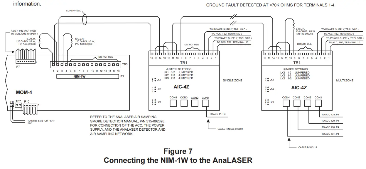
Air Sampling Interface
AnaLASER Interface
The AnaLASER Air Sampling interface connects to the MOM-4/2, TB3 or TB4, terminals 1 and 2, depending on where the NIM-1W is installed (Refer to Figure 7). Up to 31 Air Sampling detectors can be connected to a single NIM-1W.
The ACC-1 requires an RS-485 to RS-232 converter which mounts in the back of the ACC-1 enclosure. The converter model number is AIC-4Z. The AIC-4Z supports from one to four AnaLASER detectors. Refer to the AIC-4Z Installation Instructions, P/N 315093792, for the mounting and configuration of the converter and the ACC-1s.
Complete wiring of the converter as shown in Figure 7 before installing the ACC-1 in the enclosure.
- Place the end-of-line resistors in the locations specified in Figure 7.
- Install the cable P/N IC-12 between the converter and the ACC-1.
- Refer to the AnaLASER Air Sampling Smoke Detection Manual, P/N 315-092893, for connection to the AnaLASER detector and power supply, as well as mechanical mounting of the ACC-1.
- FSK @ 19.2kbps
Transmit level: 10Dbm
Receive level: 43 Dbm - Modem Ratings
14-18 AWG 10 miles Max.
20 AWG 6 miles Max.
22 AWG 4 miles Max.
0.8 uf max line to line
14-22 AWG unshielded twisted pair - Power limited to NFPA 72 per NEC 760
- Refer to NIM-1M instructions, P/N 315-099105 for
configuration settings and specific wiring guidelines - Install the LLM-1 in the MXL enclosure.
- Positive or negative ground fault detected <5K ohms on CC-5 1-16
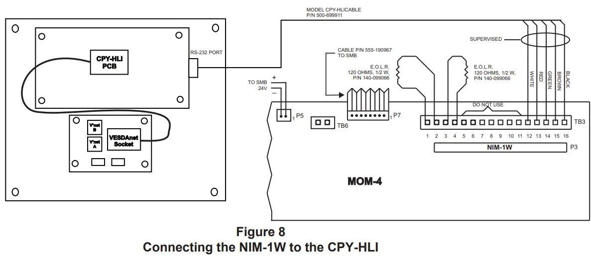
VESDA Interface
The VESDA Air Sampling interface connects to the MOM-4/2, TB3 or TB4, terminals 12-16, depending on where the NIM-1W is installed (Refer to Figure 8). Up to 31 Air Sampling detectors can be connected to a single NIM-1W.
The VESDA/MXL-IQ Intelligent Interface requires a model CPY-HLI which consists of an MXL-IQ/VESDA High Level Interface and a VESDAnet Socket. The CPY-HLI can support up to 31 VESDA detectors utilizing a VESDA network. Refer to the CPY-HLI Installation Instructions, P/N 315-099200, for mounting and installation of the CPY-HLI to the VESDA detectors.
Complete wiring of the Intelligent Interface as shown in Figure 8.
- Place the end-of-line resistors in the locations specified in Figure 8.
- Install the 5 leads of the Model CPY-HLICABLE interface cable (P/N 500-699911) to the MOM-4/2 according to the CPY-HLI Installation Instructions, P/N 315-099200. (Refer to Figure 8.)
- To connect the CPY-HLI to the VESDA network, refer to the CPY-HLI Installation Instructions, P/N 315-099200.
NOTE: VESDA is supported in NIM-1W firmware version 2.0 and higher, SMB ROM version 6.10 and higher and CSG-M version 11.01 and higher.
ELECTRICAL RATINGS
| Active 5VDC Module Current | OmA |
| Active 24VDC Module Current | 60mA |
| Standby 24VDC Module Current | 60mA |
NOTES:
- 18 AWG minimum.
- 80 ohms maximum per pair.
- Use twisted pair or shielded twisted pair.
- Terminate the shield at the NIM-1W enclosure only.
- Power limited to NFPA 70 per NEC 760.
- Maximum voltage 8V peak to peak.
- Maximum current 150mA.
- Refer to Wiring Specification for MXL, MXL-IQ and MXLV Systems, P/N 315-092772 revision 6 or higher, for additional wiring information.
MODEL CPY-HLICABLE (P/N 500-699911) Requirements:
- 18 AWG minimum.
- Maximum distance between MXL-IQ and CPY-HLI enclosures is 6 feet.
- Cable must be in rigid conduit and can not leave the room.
- Shielded cable is not recommended.
- Power limited to NFPA 70 per NEC Article 760.
REFER TO THE CPY-HLI INSTALLATION INSTRUCTIONS, P/N 315-099200, FOR MOUNTING AND INSTALLATION OF THE MODEL CPY-HLI TO THE
VESDA DETECTORS.
REFER TO WIRING SPECIFICATION FOR MXL, MXL-IQ AND MXLV SYSTEMS, P/N 315-092772 REVISION 6 OR HIGHER, FOR ADDITIONAL WIRING INFORMATION.
Siemens Industry, Inc.
Building Technologies Division
Florham Park, NJ
P/N 315-099165-10
Document ID A6V10239281
Siemens Canada Limited
Building Technologies Division
2 Kenview Boulevard
Brampton, Ontario L6T 5E4 Canada
firealarmresources.com


