![]()
![]() Addressable Interface Modules
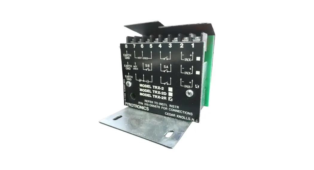
Addressable Interface Modules
Models TRX-2, TRX-2R, TRX-2D
Installation/Wiring Instructions
INTRODUCTION
The Models TRX-2 and TRX-2R are addressable interface modules that can monitor and supervise a single normally open or normally closed switch. The Model TRX-2D (dual TRX) is an addressable interface module occupying two address spaces. It can monitor and supervise two switches, either of which may be normally open or normally closed. For example, Model TRX-2D can be used to monitor and supervise a tamper switch and a waterflow switch from one TRX.
Models TRX-2 and TRX-2D are used where no relay control is required. Model TRX-2R (relay TRX) is used where relay control of external equipment is required. This module (an upgraded version of the TRX-1) has a latching type, single pole, double throw, relay contact rated:
2A at 125 VAC inductive, or 2A at 30 VDC resistive
MECHANICAL REQUIREMENTS
Models TRX-2/2R/2D are all provided with an extra terminal (terminal 8) for direct connection to Earth Ground. See WIRING INFORMATION for details.
All Model TRXs mount directly to a 3½ inch deep, double gang switchbox – no other box can be used. See MOUNTING for details.
OPERATION
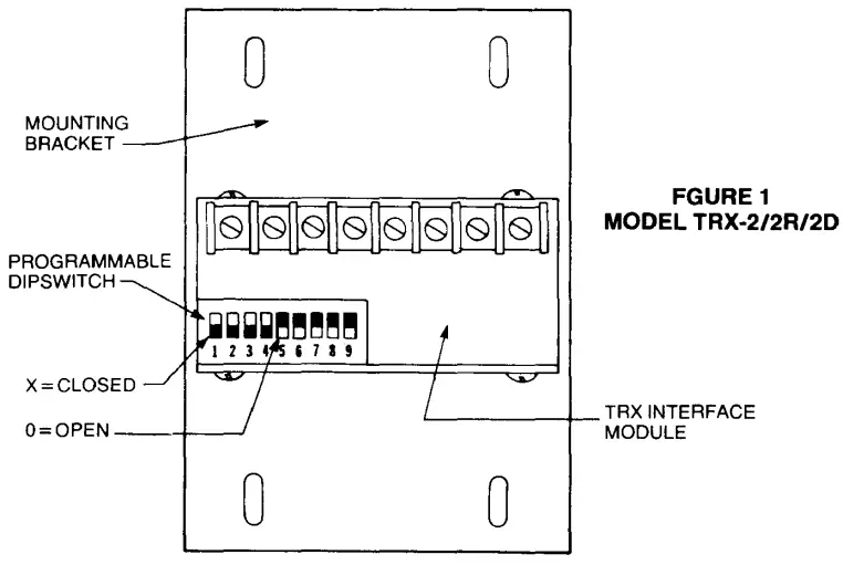
Each TRX-2 has a programmable dipswitch with switches marked 1 through 9, as shown in FIGURE 1. Switches 1-5 are used to select the unique address code for each device (See Device Address Programming below). Switches 6-9 are used to identify the type of supervised switch monitored (See Device Identification Programming below).
Device Address Programming
- Position the TRX addressable interface module as shown in FIGURE 1 and locate the programmable dipswitch.
- When using the Model TRX-2 or TRX-2R: Refer to TABLE 1 to obtain the unique address code that must be set on dipswitch switches 1-5 for that device.
- When using the Model TRX-2D: Refer to TABLE 1 to obtain the unique even address code that must be set on dipswitch
![]() A Division of CERBERUS Technologies, Inc.
A Division of CERBERUS Technologies, Inc.
8 Ridgedale Avenue, Cedar Knolls, New Jersey 07927
TABLE 1
DEVICE ADDRESS CODES
| Address | Dipswitch Settings | ||||
| 1 | 2 | 3 | 4 | 5 | |
| *1 | 0 | X | X | X | X |
| 2 | X | 0 | X | X | X |
| 3 | 0 | 0 | X | X | X |
| 4 | X | X | 0 | X | X |
| 5 | 0 | X | 0 | X | X |
| 6 | X | 0 | 0 | X | X |
| 7 | 0 | 0 | 0 | X | X |
| 8 | X | X | X | 0 | X |
| 9 | 0 | X | X | 0 | X |
| 10 | X | 0 | X | 0 | X |
| 11 | 0 | 0 | X | 0 | X |
| 12 | X | X | 0 | 0 | X |
| 13 | 0 | X | 0 | 0 | X |
| 14 | X | 0 | 0 | 0 | X |
| 15 | 0 | 0 | 0 | 0 | X |
| 16 | X | X | X | X | 0 |
| 17 | 0 | X | X | X | 0 |
| 18 | X | 0 | X | X | 0 |
| 19 | 0 | 0 | X | X | 0 |
| 20 | X | X | 0 | X | 0 |
| 21 | 0 | X | 0 | X | 0 |
| 22 | X | 0 | 0 | X | 0 |
| 23 | 0 | 0 | 0 | X | 0 |
| 24 | X | X | X | 0 | 0 |
| 25 | 0 | X | X | 0 | 0 |
| 26 | X | 0 | X | 0 | 0 |
| 27 | 0 | 0 | X | 0 | 0 |
| 28 | X | X | 0 | 0 | 0 |
| 29 | 0 | X | 0 | 0 | 0 |
| *30 | X | 0 | 0 | 0 | 0 |
X = Closed; 0 = Open
• Addresses 1 and 30 cannot be used with Model TRX-2D.
switches 1-5 for that device. (Only even numbered address codes can be selected for TRX-2D.) When the desired ad dress code is selected, the next higher address code (an odd number) will also automatically be selected, thereby setting up dual, sequential address slots.
a. Addresses 1 and 30 cannot be used with the TRX-2D.
b. Supervised switch SA, connected to terminals 3 and 4, has its status reported by the odd numbered address.
c. Supervised switch SB, connected to terminals 5 and 6, has its status reported by the even numbered address.
Device Identification Programming
- Position the addressable interface module as shown in FIGURE 1 and locate the programmable dipswitch.
- When using Model TRX-2 or Model TRX-2R, refer to TABLE 2 to select the identification code on switches 6-9 for the type of supervised switch being used. A TRX-2/2R cannot be used to replace a TRX-1 configured as a status switch.
Type of Device Dipswitch Settings TRX-1
Replacement6 7 8 9 Alarm/Trouble Causing No Alarm/Trouble Causing Status and/or Remote Relay
Remote RelayX 0 0 0 Yes
Yes
No
Yes0 0 0 0 0 0 0 X 0 0 X 0 - When using Model TRX-2D, refer to TABLE 3 to select the identification code for the types of supervised switches being monitored.
TABLE 2
TRX-2/-2R DEVICE IDENTIFICATION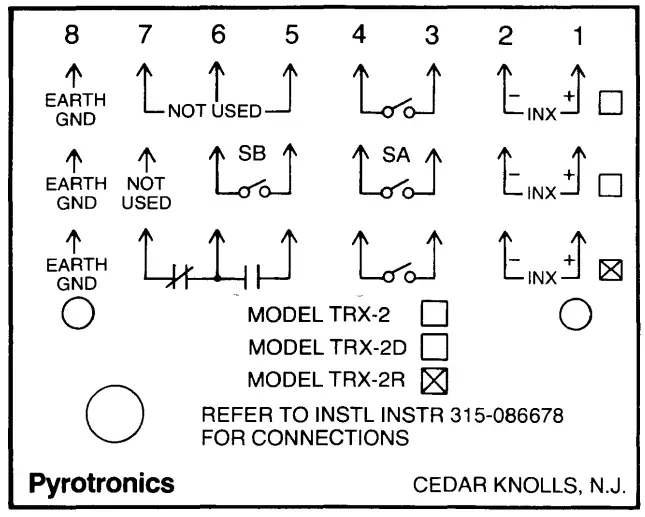 FIGURE2
MODEL TRX-2/2R/2D FACEPLATE
TABLE3
TRX-2D DEVICE IDENTIFICATION CODE
| Type of Device | Dipswitch Settings | Type of Supv Switch* | ||||
| 6 | 7 | 8 | 9 | S B | S A | |
| Trouble Causing/Status Alarm Causing/Status Alarm/Trouble Causing Dual Trouble Causing Dual Alarm Causing Dual Status | X | X | X | 0 | Trouble Causing Alarm Causing Alarm Causing Trouble Causing Alarm Causing Status | Status Status Trouble Causing Trouble Causing Alarm Causing Status |
| 0 | X | X | 0 | |||
| X | X | 0 | 0 | |||
| 0 | X | 0 | 0 | |||
| X | 0 | 0 | 0 | |||
| 0 | 0 | 0 | 0 | |||
X = Closed; O = Open
Status is intended for contact monitoring application where programmed for other than fire alarm or trouble, such as supervisory service.
- All supervised switches may be normally open or normally closed types. Only one normally closed switch may be connected per circuit.
WIRING INFORMATION
- Position the addressable interface module as shown in FIGURE 1.
- Refer to the wiring information on the faceplate (See FIGURE 2). Each module has an X marked to indicate the type of model and another X marked to indicate the wiring connections to be made to that module.
- Refer to the appropriate wiring diagram (FIGURE 3, 4, or 5) and wire the addressable interface module accordingly. model and another X marked to indicate the wiring connections to be made to that module.
- Refer to the appropriate wiring diagram (FIGURE 3, 4, or 5) and wire the addressable interface module accordingly.
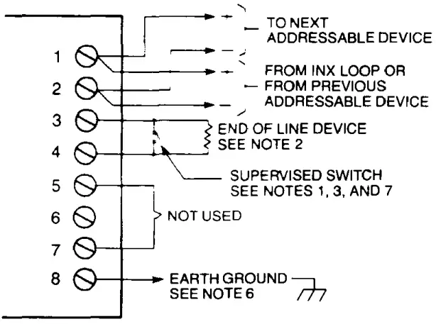 FIGURE3
MODEL TRX-2 WIRING 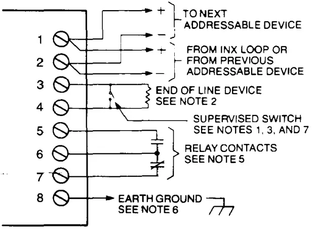 FIGURE4
MODEL TRX-2R WIRING 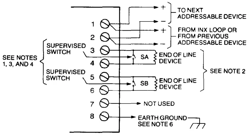 FIGURE 5
MODEL TRX-2D WIRING
NOTES
- All supervised switches must be held closed and/or open for at least 1 O seconds in order to guarantee detection.
- End of line device: 27K, 1/4W resistor.
- The supervised switches have the following ratings:
Voltage maximum 14 VDC Current maximum 3mA during polling Contact resistance 10 ohms Maximum cable length 200 feet (18 AWG) Maximum capacitance:
CLine to shield = .04uFCLine to line = .02uF - Supervised Switch SA is supervised on odd numbered addresses only. Supervised Switch SB is supervised on even numbered addresses only.
- Relay contacts are rated:
2A, 125 VAC inductive, or 2A, 30 VDC resistive
The relay is shown in standby condition. - Earth Ground is the INX wiring shield when using shielded cable, or the conduit when not using shielded cable.
- A TRX-2/2R cannot be used to replace a TRX-1 configured as a status switch.
MOUNTING
Addressable Interface Model TRX-2, TRX-2D, or TRX-2R mounts directly into a 3½ inch deep, double gang switchbox (user supplied) only. Each module is secured to the switchbox with a standard blank, double gang swashplate (also user supplied). Refer to FIGURE 6 for details.
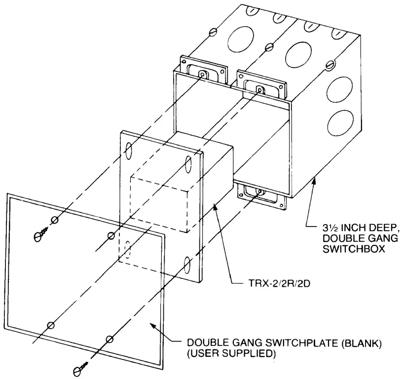 FIGURE 6
MOUNTING THE TRX-2/2R/2D
PIN 315-086678C
firealarmresources.com


