![]() Haiwell PLC User Manual
Haiwell PLC User Manual
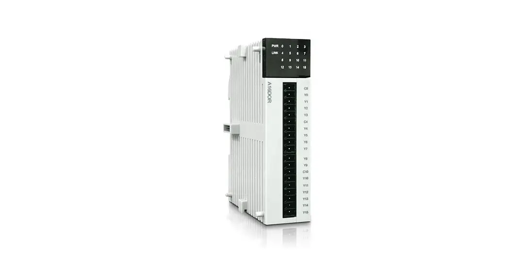
A Series Card-type PLC
Analog Module User Manual & Application Cases
Analog Module User Manual
Product Model List and Dimension
| Model | Power (24V) | Dimension |
| A04AI | DC24V~0.1A MAX | 25*95*65 mm |
| A04AO | DC24V~0.1A MAX | |
| A04XA | DC24V~0.1A MAX | |
| A08AI | DC24V~0.1A MAX | |
| A08A0 | DC24V~0.15A MAX |
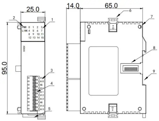
- Indicator
- PWR power indicator, LINK module communication indicator
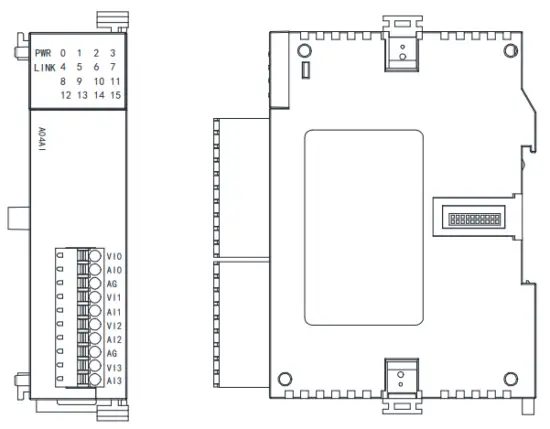
- Terminal definition
- Removable terminal
- Guide rail buckle
- Module lock buckle
- Module positioning hole
- Module extension port
- 35mm DIN guide rail track
Indicator Description
- PWR: power indicator. green, constant light -Power normal; Not light – Power abnormal.
- LINK: multi-status indicator. three colors (Red. Yellow. Green), as follow:
| Reference processing mode | Module bus state | LINK indicator state |
| Normal | No communication of module | No light |
| MPU has identified the module but no communication | Constant light in green | |
| Serial or parallel port in communication | Green jitter: indicator on 30ms and off 30ms | |
| A parallel power supply is not enough, must connect to the external power supply | Without serial or parallel port in communication | Yellow flicker: indicator on 0.5s and off 0.5s |
| With the serial or parallel port in communication | Yellow is darkened and jitter alternately: indicator off 0.5s and jitter 0.5s | |
| Firmware upgrade failed, re-upgrade the module firmware | Without serial or parallel port in communication | Red flicker: indicator on 0.5s and off 0.5s |
| With the serial or parallel port in communication | Red is darkened and jitter alternately: indicator off 0.5s and jitter 0.5s | |
| Hardware failure and maintenance | Without serial or parallel port in communication | Constant light in red |
Power Supply Specification
| Item | DC Power Supply |
| Power supply voltage | 24VDC -15%—+20% |
| Power supply frequency | ______ |
| Instantaneous surge | MAX 20A 1.5ms @24VDC |
| Power loss time | 10ms or less |
| Fuse | 0.3A, 250V |
| 24V Output voltage (for input and expansion) | None |
| Isolation Type | No Electrical isolation |
| Power Protection | DC input power polarity reverse, over-voltage protection |
Environmental Specifications for Product
| Item | Environment Specification |
| Temperature/Humidity | Operating temperature:0~+55℃ Storage temperature:-25~+70℃ Humidity: 5~95%RH, No condensation |
| Vibration Resistance | 10~57 HZ, amplitude=0.075mm, 57HZ~150HZ acceleration=1G, 10 times each for X-axis, Y-axis and Z-axis |
| Impact Resistance | 15G, duration=11ms, 6 times each for X-axis, Y-axis, and Z-axis |
| Interference Immunity | DC EFT:±2500V Surge:±1000V |
| Over-Voltage Resistance | 1500VAC/1min between AC terminal and PE terminal, 500VAC/1min between DC terminal and PE terminal |
| Insulation Impedance | Between AC terminal and PE terminal @500VDC,>=5MΩ, all input/output points to PE terminal @500VDC |
| Operating environment | Avoid dust, moisture, corrosion, electric shock, and external shocks |
Analog Input (AI) Specification
| Item | Voltage input | Current input | ||
| Input range | OV-+10V | OV-+5V | 1V-+5V | 0-20mA 4-20mA |
| Resolution | 2.5mV | 1.25mV | 1.25mV | 5pA |
| Input impedance | 6M0 | 2500 | ||
| Maximum input range | ±13V | ± 30mA | ||
| Input indication | LED light ON means normal OFF means external disconnect | |||
| Response time | 5ms14 Channel | |||
| Digital input range | 12 bits, Code range:0-32000(H series module 16 bits ND convert) | |||
| Precision | 0.2% F.S | |||
| Power supply | MPU uses an internal power supply, the extended module uses an external power supply of 24VDC ±10% 5VA | |||
| Isolation mode | Optoelectronic isolation, Non-isolation between Channels, between analog and digital is optoelectronic isolation | |||
| Power consumption | 24VDC ±20%,100mA(maximum) | |||
Analog Output (AQ) Specification
Item | Voltage output | Current output | |||
| Output range | OV- +10V | OV-+5V | 1V-+5V | 0-20mA | 4-20mA |
| Resolution | 2.5mV | 1.25mV | 1.25mV | 5uA | 5uA |
| Output load impedance | 1K0@10V | 5000@10V | ≤500Ω | ||
| Output indication | LED ON means normal | ||||
| Drive capability | 10mA | ||||
| Response time | 3ms | ||||
| Digital output range | 12 bits, Code range:0-32000(H series module 16 bits D/A convert) | ||||
| Precision | 0.2% F.S | ||||
| Power supply | MPU uses an internal power supply, and expansion modules use an external power supply of 24VDC ±10% 5VA | ||||
| Isolation mode | Optoelectronic isolation, Non-isolation between Channels, between analog and digital is optoelectronic isolation | ||||
| Power consumption | 24VDC ±20%,100mA(maximum) | ||||
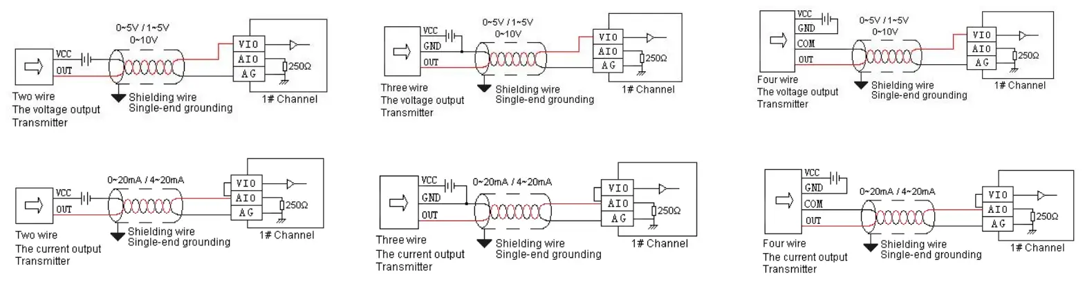
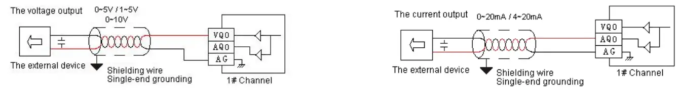
Analog Input (AI) Wiring Diagram
Analog Output (AQ) Wiring Diagram
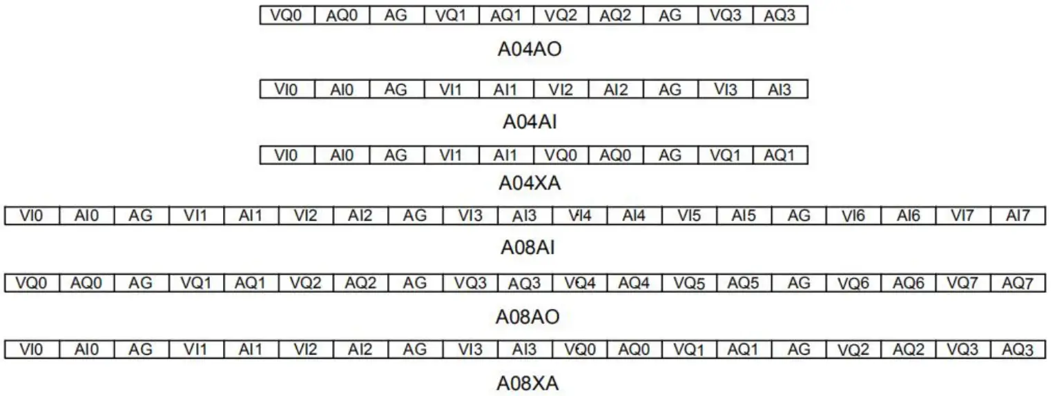
Terminal Diagram
Module Parameter Table
(CR code is corresponding to the Modbus register address)
4-channel analog module parameter table
Note: CR code is corresponding to the Modbus register address, the ray parts are read-only, and the white parts are readable and writable.
| CR code | Function Description | ||
| A04AI | A04AO | A04XA | |
| 00H | Low byte for module code, and high byte for the module version number. | ||
| 01H | Communication address | ||
| 02H | Communication protocol: The low 4-bit of the low byte: 0 – N,8,2 For RTU, 1 – E,8,1 For RTU, 2 – O,8,1 For RTU, 3 – N,7,2 For ASCII, 4 – E,7,1 For ASCII, 5 – O,7,1 For ASCII, 6 – N,8, 1 For RTU The high 4-bit of the low byte: 0 – 2400, 1 – 4800, 2 – 9600, 3 – 19200, 4 – 38400, 5 – 57600, 6 – 115200 | ||
| CR code | Function Description | ||
| A04AI | A04AO | A04XA | |
| 03H~06H | Module name | ||
| 07H~08H | Default IP address: 192.168.1.111 | ||
| 09~0AH | Reserve | ||
| 0BH | High byte subnet mask (b3~b0,1 indicates 255, 0 indicates 0, for example subnet mask 255.255.255.0, b3~b0=1110), low byte reserved | ||
| 0CH-0EH | Reserve | ||
| 0FH | Error code: 0-Normal, 1-Illegal firmware identity, 2-Incomplete firmware, 3-System data access exception, 4-No external 24V power supply | ||
| 10H | channel 1 input value | channel 1 output value | input channel 1 input value |
| 11H | channel 2 input value | channel 2 output value | input channel 2 input value |
| 12H | channel 3 input value | channel 3 output value | input channel 1 signal type, note 2 |
| 13H | channel 4 input value | channel 4 output value | input channel 2 signal type, note 2 |
| 14H | channel 1 signal type, note 2 | channel 1 signal type, note 2 | Use the engineering value mark, note 6 |
| 15H | channel 2 signal type, note 2 | channel 2 signal type, note 2 | input channel 1 engineering lower limiting value |
| 16H | channel 3 signal type, note 2 | channel 3 signal type, note 2 | input channel 2 engineering lower limiting value |
| 17H | channel 4 signal type, note 2 | channel 4 signal type, note 2 | input channel 1 engineering upper limiting value |
| 18H | Use the engineering value mark, note 6 | Use the engineering value mark, note 6 | input channel 2 engineering upper limiting value |
| 19H | channel 1 engineering lower limiting value | channel 1 engineering lower limiting value | input channel 1 sampling frequency, note 1 |
| 1AH | channel 2 engineering lower limiting value | channel 2 engineering lower limiting value | input channel 2 sampling frequency, note 1 |
| 1BH | channel 3 engineering lower limiting value | channel 3 engineering lower limiting value | input channel 1 zero point correction value |
| 1CH | channel 4 engineering lower limiting value | channel 4 engineering lower limiting value | input channel 2 zero point correction value |
| 1DH | channel 1 engineering upper limiting value | channel 1 engineering upper limiting value | Channel 1~2 input disconnection alarm, note 5 |
| 1EH | channel 2 engineering upper limiting value | channel 2 engineering upper limiting value | output channel 1 output value |
| 1FH | channel 3 engineering upper limiting value | channel 3 engineering upper limiting value | output channel 2 output value |
| 20H | channel 4 engineering upper limiting value | channel 4 engineering upper limiting value | output channel 1 signal type, note 2 |
| 21H | channel 1 sampling frequency, note 1 | power-off output mark, note 8 | output channel 2 signal type, note 2 |
| 22H | channel 2 sampling frequency, note 1 | channel 1 power-off output value | Use the engineering value mark, note 6 |
| 23H | channel 3 sampling frequency, note 1 | channel 2 power-off output value | output channel 1 engineering lower limiting value |
| 24H | Channel 4 sampling frequency, note 1 | channel 3 power-off output value | output channel 2 engineering lower limiting value |
| 25H | channel 1 zero point correction value | channel 4 power-off output value | output channel 1 engineering upper limiting value |
| 26H | channel 2 zero point correction value | Channel indicator status, note 7 | output channel 2 engineering upper limiting value |
| 27H | channel 3 zero point correction value | Reserve | power-off output mark, note 8 |
| 28H | channel 4 zero point correction value | output channel 1 power-off output value | |
| 29H | Channel 1~4 input disconnection alarm, note 5 | output channel 2 power-off output value | |
| 2AH | Reserve | output channel indicator, note 7 | |
| 2BH~2FH | Reserve | ||
channel analog module parameter table
Note: CR code is corresponding to the Modbus register address, the gray parts are read-only, and the white parts are readable and writable.
| CR code | Function description | ||
| A08AI | A08AO | A08XA | |
| 00H | Low byte for module code, and high byte for the module version number. | ||
| 01H | Communication address | ||
| 02H | Communication protocol: The low 4-bit of the low byte: 0 – N,8,2 For RTU, 1 – E,8,1 For RTU, 2 – O,8,1 For RTU, 3 – N,7,2 For ASCII, 4 – E,7,1 For ASCII, 5 – O,7,1 For ASCII, 6 – N,8, 1 For RTU The high 4-bit of the low byte: 0 – 2400, 1 – 4800, 2 – 9600, 3 – 19200, 4 – 38400, 5 – 57600, 6 – 115200 | ||
| 03H~06H | Module name | ||
| 07H~08H | Default IP address: 192.168.1.111 | ||
| 09~0AH | Reserve | ||
| 0BH | High byte subnet mask (b3~b0,1 indicates 255, 0 indicates 0, for example subnet mask 255.255.255.0, b3~b0=1110), low byte reserved | ||
| 0CH~0EH | Reserve | ||
| 0FH | Error code: 0-Normal, 1-Illegal firmware identity, 2-Incomplete firmware, 3-System data access exception, 4-No external 24V power supply | ||
| 10H | channel 1 input value | channel 1 output value | input channel 1 input value |
| 11H | channel 2 input value | channel 2 output value | input channel 2 input value |
| 12H | channel 3 input value | channel 3 output value | input channel 3 input value |
| 13H | channel 4 input value | channel 4 output value | input channel 4 input value |
| 14H | channel 5 input value | channel 5 output value | input channel 1 signal type, note 2 |
| 15H | channel 6 input value | channel 6 output value | input channel 2 signal type, note 2 |
| 16H | channel 7 input value | channel 7 output value | input channel 3 signal type, note 2 |
| 17H | channel 8 input value | channel 8 output value | input channel 4 signal type, note 2 |
| 18H | channel 1 signal type, note 2 | channel 1 signal type, note 2 | Use the engineering value mark, note 6 |
| 19H | channel 2 signal type, note 2 | channel 2 signal type, note 2 | input channel 1 engineering lower limiting value |
| 1AH | channel 3 signal type, note 2 | channel 3 signal type, note 2 | input channel 2 engineering lower limiting value |
| 1BH | channel 4 signal type, note 2 | channel 4 signal type, note 2 | input channel 3 engineering lower limiting value |
| 1CH | channel 5 signal type, note 2 | channel 5 signal type, note 2 | input channel 4 engineering lower limiting value |
| 1DH | channel 6 signal type, note 2 | channel 6 signal type, note 2 | input channel 1 engineering upper limiting value |
| 1EH | channel 7 signal type, note 2 | channel 7 signal type, note 2 | input channel 2 engineering upper limiting value |
| 1FH | channel 8 signal type, note 2 | channel 8 signal type, note 2 | input channel 3 engineering upper limiting value |
| 20H | Use the engineering value mark, note 6 | Use the engineering value mark, note 6 | input channel 4 engineering upper limiting value |
| 21H | channel 1 engineering lower limiting value | channel 1 engineering lower limiting value | input channel 1 sampling frequency, note 1 |
| 22H | channel 2 engineering lower limiting value | channel 2 engineering lower limiting value | input channel 2 sampling frequency, note 1 |
| 23H | channel 3 engineering lower limiting value | channel 3 engineering lower limiting value | input channel 3 sampling frequency, note 1 |
| 24H | channel 4 engineering lower limiting value | channel 4 engineering lower limiting value | input channel 4 sampling frequency, note 1 |
| 25H | channel 5 engineering lower limiting value | channel 5 engineering lower limiting value | input channel 1 zero point correction value |
| 26H | channel 6 engineering lower limiting value | channel 6 engineering lower limiting value | input channel 2 zero point correction value |
| 27H | channel 7 engineering lower limiting value | channel 7 engineering lower limiting value | input channel 3 zero point correction value |
| 28H | channel 8 engineering lower limiting value | channel 8 engineering lower limiting value | input channel 4 zero point correction value |
| 29H | channel 1 engineering upper limiting value | channel 1 engineering upper limiting value | Channel 1~4 input disconnection alarm, note 5 |
| 2AH | channel 2 engineering upper limiting value | channel 2 engineering upper limiting value | output channel 1 output value |
| 2BH | channel 3 engineering upper limiting value | channel 3 engineering upper limiting value | output channel 2 output value |
| 2CH | channel 4 engineering upper limiting value | channel 4 engineering upper limiting value | output channel 3 output value |
| 2DH | channel 5 engineering upper limiting value | channel 5 engineering upper limiting value | output channel 4 output value |
| 2EH | channel 6 engineering upper limiting value | channel 6 engineering upper limiting value | output channel 1 signal type, note 2 |
| 2FH | channel 7 engineering upper limiting value | channel 7 engineering upper limiting value | output channel 2 signal type, note 2 |
| 30H | channel 8 engineering upper limiting value | channel 8 engineering upper limiting value | output channel 3 signal type, note 2 |
| 31H | channel 1 sampling frequency, note 1 | power-off output mark | output channel 4 signal type, note 2 |
| 32H | channel 2 sampling frequency, note 1 | channel 1 power-off output value | Use the engineering value mark, note 6 |
| 33H | channel 3 sampling frequency, note 1 | channel 2 power-off output value | output channel 1 engineering lower limiting value |
| 34H | channel 4 sampling frequency, note 1 | channel 3 power-off output value | output channel 2 engineering lower limiting value |
| 35H | channel 5 sampling frequency, note 1 | channel 4 power-off output value | output channel 3 engineering lower limiting value |
| 36H | channel 6 sampling frequency, note 1 | channel 5 power-off output value | output channel 4 engineering lower limiting value |
| 37H | channel 7 sampling frequency, note 1 | channel 6 power-off output value | output channel 1 engineering upper limiting value |
| 38H | channel 8 sampling frequency, note 1 | channel 7 power-off output value | output channel 2 engineering upper limiting value |
| 39H | channel 1 zero point correction value | channel 8 power-off output value | output channel 3 engineering upper limiting value |
| 3AH | channel 2 zero point correction value | Channel indicator status | output channel 4 engineering upper limiting value |
| 3BH | channel 3 zero point correction value | Reserve | power-off output mark |
| 3CH | channel 4 zero point correction value | output channel 1 power-off output value | |
| 3DH | channel 5 zero point correction value | output channel 2 power-off output value | |
| 3EH | channel 6 zero point correction value | output channel 3 power-off output value | |
| 3FH | channel 7 zero point correction value | output channel 4 power-off output value | |
| 40H | channel 8 zero point correction value | output channel indicator | |
| 41H | Channel 1~8 input disconnection alarm, note 5 | Reserve | |
| 42H~4FH | Reserve |
Note:
- Sampling frequency:0 – 2 times, 1 – 4 times, 2 – 8 times, 3 – 16 times, 4 – 32 times, 5 – 64 times, 6 – 128 times, 7 – 256 times
- Signal type: 0 – [4,20]mA, 1 – [0,20]mA, 2 – [1,5]V, 3 – [0,5]V, 4 – [0,10]V
- Disconnection alarm: Each bit indicates 1 channel, 0-normal, 1-disconnection
- Use the engineering value mark: Each bit indicates 1 channel, 0-No, 1-Yes
- Channel indicator status: Each bit indicates 1 channel, 0-off, 1-on
- Power-off output mark: Each bit indicates 1 channel, 0-No, 1-Yes
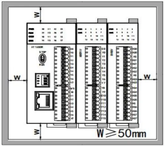
Mounting and installation
The PLC should be secured to an enclosed cabinet while mounting. For heat dissipation, make sure to provide a minimum
clearance of 50mm between the unit and all sides of the cabinet. (See the figure.)
Rail Mounting: Use standard 35 mm rail.
Connecting Extended Module
Join the lower right parallel interface of the Last module (Host or Extension Module ) to the lower right of the parallel interface of next
module, then tight with two buckles on top and bottom.
The interface of the right side module is left for the extension interface for the next extension module.
Analog Module Application Case
Expand module through the host PLC parallel port
Module power supply
![]() An Analog module can be the expansion module for an A series PLC; When the module is directly connected to the host PLC, no need to take an external power supply, the module is powered by the host PLC.
An Analog module can be the expansion module for an A series PLC; When the module is directly connected to the host PLC, no need to take an external power supply, the module is powered by the host PLC.
The analog needn’t be written any conversion program, read the analog register value directly.
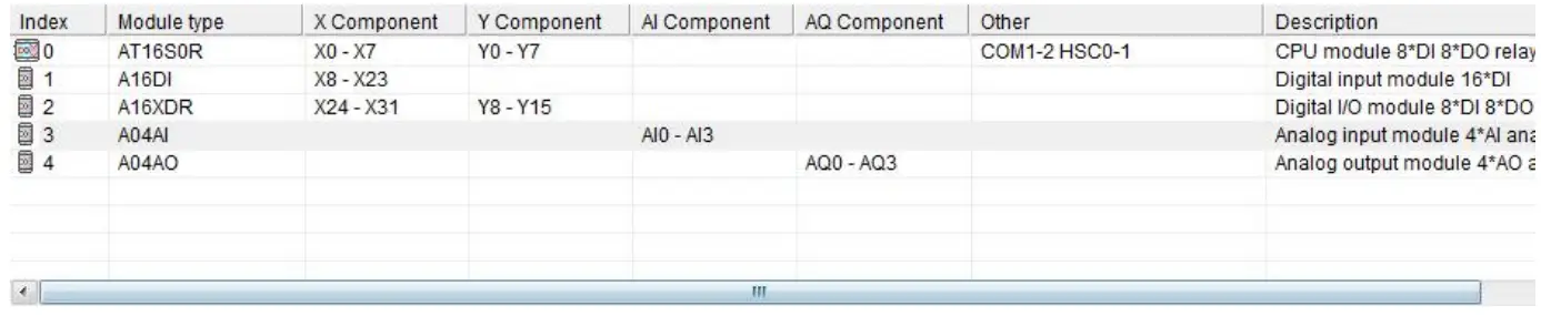
For example, the host PLC AT16S0R, respectively, is expanded with three modules of A16DI, A16XDR, A04AI, and A04AO from left to right, assuming the scene:
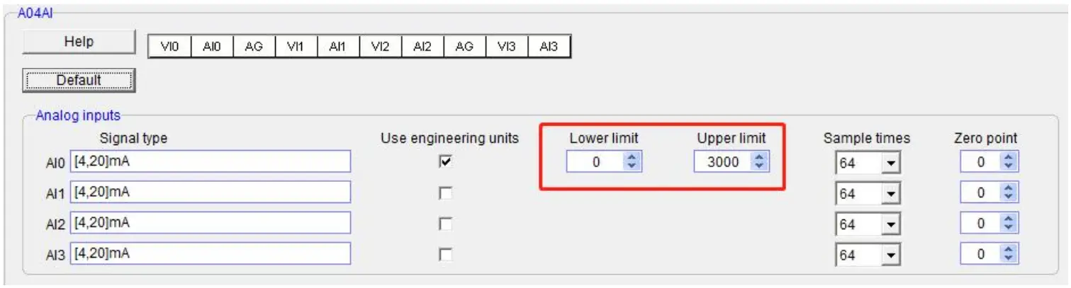
- Analog module A04AI input channel 1, signal type is 4-20mA, used to measure the pressure, the pressure range of 0.0~3.0Mpa;
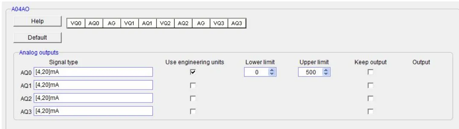
- Analog module A04AO input channel 1, signal type is 0-10V, used to control the inverter frequency of 0.0~50.0Hz;
First, enter the PLC programming software menu bar – view – hardware configuration, in accordance with the external order of actual modules to add the module models, after added, the analog address will be automatically arranged, as shown below:
Haiwell analog module needn’t be written any conversion program, as for above pressure measurement, we only need to check the use of engineering value, set the lower limit value of 0 corresponding 0.0Mpa, set the upper limit value of 3000 indicating 3.000Mpa, the upper limit value 3000 hidden three decimal places can achieve magnification times and improve accuracy. Then we read the value of the analog input register AI0, if AI0 = 1234, then the actual value is 1.234Mpa.
Similarly, for the analog output, check the use of engineering value, set the lower limit value of 0 indicating 0.0Hz, and set the upper limit value of 500 indicating 50.0Hz, if you want the inverter frequency output to be 25.6Hz, as long as the force the AQ0 value as 256 or through other logic instructions to output the AQ0 value of 256. As shown below:
Programming skills
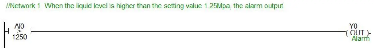
If you want to write the alarm program that pressure exceeds the setting value, for example, when the pressure is more than 1.25Mpa, it will alarm, the program of PLC can be written as follows:
Display analog value on SCADA, HMI
If the SCADA, touch screen, text, and other PC software want to display the current pressure, and only need to set three decimal digits on the numerical display primitive, then the real value will be automatically reduced 1000 times in the configuration, that is the actual temperature value, for example, you can set 3 on decimal digits of Haiwell Cloud SCADA settings.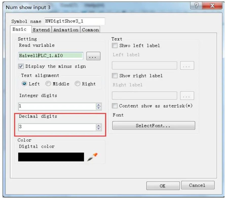
So that when the PLC read AI0 value, AI0=1234, that is the actual value of 1.234Mpa, there is no need to have data processing in PLC and configuration, only set the 3 decimal places on the numerical display primitive, then it will be automatically reduced by 1000 times, displaying the value of 1.234, that is the actual value of 1.234Mpa.
When the engineering value is not used, the default code value is 0 ~ 32000
When using the engineering value, the linear transformation is specified by the lower limit and the upper limit value, and the program is automatically transformed. When the engineering value is not used, all types are unified to correspond with 0 ~ 32000 code values.In the same case of pressure measurement, this time can according to the linear transformation formula: Out = (In – InDw) * (OutUp- OutDw) / (InUp- InDw) + OutDw to write the conversion program, or use the SC linear transformation instructions to calculate directly.
Haiwell analog is used easily, it is recommended to check the use of engineering value so that the analog will be very convenient without writing any program.
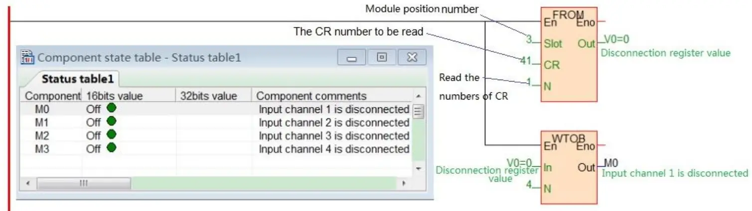
Module CR code application example: Read the module channel disconnection alarm
In this example, in order to read the external sensor disconnection information of the A08XA module, the disconnection alarm data of the A08XA module input channel 1-4 is stored in CR29, that is, 29H (hexadecimal), decimal 41. (More CR contents can be found in the software online help – hardware manual – expansion module parameters within the corresponding model). This program is as follows:
- Slot: Position number, A08XA is the third module, so fill in 3;
- CR: Module disconnection alarm CR41, that is, 29H (hexadecimal) = 41 (decimal), can be directly input 41 or 0x29 into the instruction CR terminal;
- N: Number for readings, 1 register for 16 bits, low 4 bits corresponding channel 1-4, disconnection for 1 (ON), normal for 0 (OFF).
Thanks for choosing Haiwell Products, If you have any questions about our products or services, please let us know!
Harwell website: www.haiwell.com Copyright © 2005 Xiamen Haiwell Technology Co., Ltd.
Xiamen Haiwell Technology Co., Ltd. en.haiwell.com


