
 unitronics Vision PLC+HMI Programmable Logic Controller
Vision™PLC+HMI User Guide
| Vision™PLC+HMI | User Guide | |
| V130-33-RA22/V130-J-RA22 V350-35-RA22/V350-J-RA22 V430-J-RA22 | § 12 Digital Inputs, including 1 HSC/Shaft-encoder Inputs, 2 Analog, 2 PT100/TC inputs | |
| § 8 Relay Outputs | § 2 Analog Outputs | |
| V130-33-TRA22/V130-J-TRA22 V350-35-TRA22/V350-J-TRA22 V430-J-TRA22 | § 12 Digital Inputs, including 1 HSC/Shaft-encoder Inputs, 2 Analog Inputs, 2 PT100/TC inputs | |
| § 4 Relay Outputs | § 2 Analog Outputs | |
| § 4 high-speed npn Transistor Outputs | ||
General Description
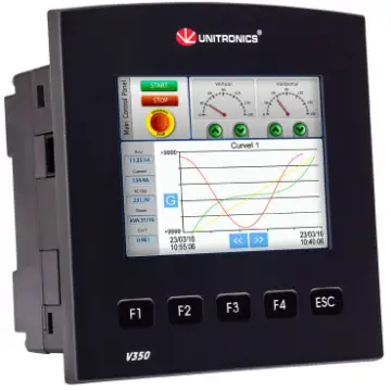
The products listed above are micro-PLC+HMIs, rugged programmable logic controllers that comprise built-in operating panels.
Detailed Installation Guides containing the I/O wiring diagrams for these models, technical specifications, and additional documentation are located in the Technical Library in the Unitronics website: https://unitronicsplc.com/support-technical-library/
| Item | V130-RA22 V130J-RA22 | V130-TRA22 V130J-TRA22 | V350-RA22 V350J-RA22 | V350-TRA22 V350J-TRA22 | V430J-RA22 V430J-TRA22 |
| On-board I/O | Model Dependent | ||||
| Screen | 2.4″ | 3.5″ Color Touch | 4.3″ Color Touch | ||
| Keypad | Yes | None | |||
| Function Keys | None | Yes | |||
| Com Port, Built-in | |||||
| RS232/485 | Yes | Yes | Yes* | Yes* | Yes* |
| USB device, mini-B | None | None | Yes* | Yes* | Yes* |
| Com Ports, separate order, user-installed | The user may install a CANbus port (V100-17-CAN), and one of the following: · RS232/RS485 port (V100-17-RS4/V100-17-RS4X) · Ethernet (V100-17-ET2) · Profibus Slave (V100-17-PB1) | ||||
| * V430J/V350/V350J comprises both RS232/485 and USB ports; note that only one channel may be used at a time. | |||||
Standard Kit Contents
| Item | V130-RA22 V130J-RA22 | V130-TRA22 V130J-TRA22 | V350-RA22 V350J-RA22 | V350-TRA22 V350J-TRA22 | V430J-RA22 V430J-TRA22 |
| Controller | Yes | ||||
| Terminal Blocks | Yes | ||||
| Battery (installed) | Yes | ||||
| Slides (2 sets of key labels) | None | Yes | None | ||
| Mounting Brackets | Yes (2 parts) | Yes (4 parts) | |||
| Rubber Seal | Yes | ||||
Alert Symbols and General Restrictions
| Alert Symbols and General Restrictions | ||
| When any of the following symbols appear, read the associated information carefully. | ||
| Symbol | Meaning | Description |
 | Danger | The identified danger causes physical and property damage. |
 | Warning | The identified danger could cause physical and property damage. |
| Caution | Caution | Use caution. |
| § Before using this product, the user must read and understand this document. § All examples and diagrams are intended to aid understanding, and do not guarantee operation. Unitronics accepts no responsibility for actual use of this product based on these examples. § Please dispose of this product according to local and national standards and regulations. § Only qualified service personnel should open this device or carry out repairs. | ||
| § Failure to comply with appropriate safety guidelines can cause severe injury or property damage. | ||
| § Do not attempt to use this device with parameters that exceed permissible levels. § To avoid damaging the system, do not connect/disconnect the device when power is on. | ||
Environmental Considerations
|
| § Do not install in areas with: excessive or conductive dust, corrosive or flammable gas, moisture or rain, excessive heat, regular impact shocks or excessive vibration, in accordance with the standards given in the product’s technical specification sheet. § Do not place in water or let water leak onto the unit. § Do not allow debris to fall inside the unit during installation. |
| § Ventilation: 10mm space required between controller’s top/bottom edges & enclosure walls. § Install at maximum distance from high-voltage cables and power equipment. | |
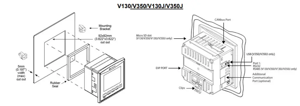
Mounting
Note that figures are for illustrative purposes only.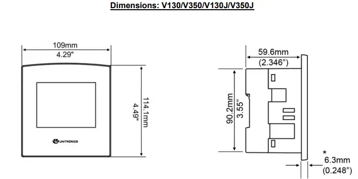 Note that for models V130/V350, the bezel width is up to 8.4 mm (0.33”).
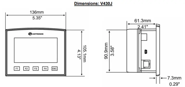
| Model | Cut-out | View area |
| V130V130J | 92×92 mm (3.622”x3.622”) | 58×30.5mm (2.28″x1.2″) |
| V350/V350J | 92×92 mm (3.622”x3.622”) | 72×54.5mm (2.95″x2.14″) |
| V430J | 122.5×91.5 mm (4.82”x3.6”) | 96.4×55.2mm (3.79″x2.17″) |
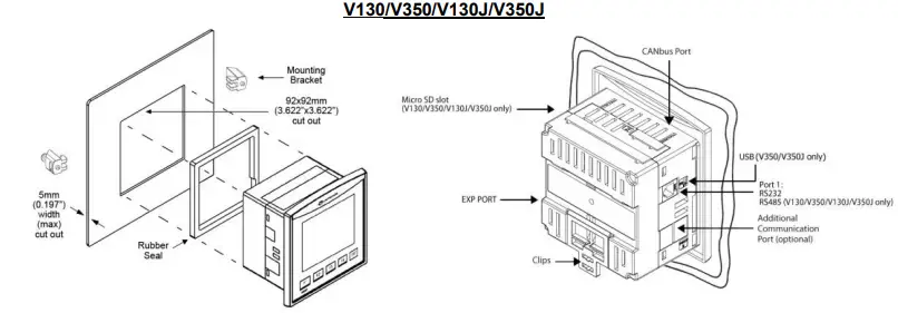
Panel Mounting
Before you begin, note that the mounting panel cannot be more than 5 mm thick.
- Make a panel cut-out of the appropriate size:
- Slide the controller into the cut-out, ensuring that the rubber seal is in place.
- Push the mounting brackets into their slots on the sides of the panel as shown in the figure below.
- Tighten the bracket’s screws against the panel. Hold the bracket securely against the unit while tightening the screw.
- When properly mounted, the controller is squarely situated in the panel cut-out as shown in the accompanying figures.


DIN-rail Mounting (V130/V350/V130J/V350J) 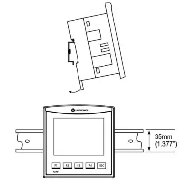
- Snap the controller onto the DIN rail as shown in the figure to the right.
- When properly mounted, the controller is squarely situated on the DIN-rail as shown in the figure to the right.
UL Compliance
The following section is relevant to Unitronics’ products that are listed with the UL.
The following models: V130-33-R34, V130-J-R34, V130-T4-ZK1, V350-35-RA22, V350-J-RA22, V350-35-R34, V350-J-R34, V430-J-R34
are UL listed for Hazardous Locations.
The following models: V130-33-B1,V130-J-B1,V130-33-TA24,V130-J-TA24,V130-33-T38,V130-J-T38 V130-33-TR20,V130-J-TR20,V130-33-TR34,V130-J-TR34,V130-33-RA22,V130-J-RA22, V130-33-TRA22,V130-J-TRA22,V130-33-T2,V130-J-T2,V130-33-TR6,V130-J-TR6,V130-33-R34, V350-35-B1, V130-T4-ZK1, V350-J-B1,V350-35-TA24,V350-J-TA24,V350-35-T38,V350-J-T38, V350-35-TR20,V350-J-TR20,V350-35-TR34,V350-J-TR34,V350-35-TRA22,V350-J-TRA22, V350-35-T2,V350-J-T2,V350-35-TR6,V350-J-TR6,V350-S-TA24,V350-JS-TA24,V350-35-RA22, V350-J-RA22,V350-35-R34, V430-J-B1,V430-J-TA24,V430-J-T38, V430-J-R34,V430-J-RH2, V430-J-TR34,V430-J-RA22,V430-J-TRA22,V430-J-T2,V430-J-RH6
are UL listed for Ordinary Location.
For models from series V130, V130-J, V430, that include “T4” or “J4” in the Model name, Suitable for mounting on the flat surface of Type 4X enclosure.
For examples: V130-T4-R34, V130-J4-R34, V430-J4-T2
UL Ordinary Location
In order to meet the UL ordinary location standard, panel-mount this device on the flat surface of Type 1 or 4 X enclosures
UL Ratings, Programmable Controllers for Use in Hazardous Locations, Class I, Division 2, Groups A, B, C and D
These Release Notes relate to all Unitronics products that bear the UL symbols used to mark products that have been approved for use in hazardous locations, Class I, Division 2, Groups A, B, C and D.
Caution
- This equipment is suitable for use in Class I, Division 2, Groups A, B, C and D, or Non-hazardous locations only.
- Input and output wiring must be in accordance with Class I, Division 2 wiring methods and in accordance with the authority having jurisdiction.
- WARNING—Explosion Hazard—substitution of components may impair suitability for Class I, Division 2.
- WARNING – EXPLOSION HAZARD – Do not connect or disconnect equipment unless power has been switched off or the area is known to be non-hazardous.
- WARNING – Exposure to some chemicals may degrade the sealing properties of material used in Relays.
- This equipment must be installed using wiring methods as required for Class I, Division 2 as per the NEC and/or CEC.
Panel-Mounting
For programmable controllers that can be mounted also on panel, in order to meet the UL Haz Loc standard, panel-mount this device on the flat surface of Type 1 or Type 4X enclosures.
Relay Output Resistance Ratings
The products listed below contain relay outputs:
Programmable controllers, Models: V430-J-R34, V130-33-R34,V130-J-R34 and V350-35-R34, V350-J-R34
- When these specific products are used in hazardous locations, they are rated at 3A res.
- Except for models V430-J-R34, V130-33-R34, V130-J-R34, V130-T4-ZK1 and V350-35-R34, V350-J-R34,when these specific products are used in non-hazardous environmental conditions, they are rated at 5A res, as given in the product’s specifications.
Communication and Removable Memory Storage
When products comprise either USB communication port, SD card slot, or both, neither
the SD card slot nor the USB port are intended to be permanently connected, while the USB port is intended for programming only.
Removing / Replacing the battery
When a product has been installed with a battery, do not remove or replace the battery unless the power has been switched off, or the area is known to be non-hazardous. Please note that it is recommended to back up all data retained in RAM, in order to avoid losing data when changing the battery while the power is switched off. Date and time information will also need to be reset after the procedure.
Wiring
- Do not touch live wires.
- Install an external circuit breaker. Guard against short-circuiting in external wiring.
- Use appropriate circuit protection devices.
- Unused pins should not be connected. Ignoring this directive may damage the device.
- Double-check all wiring before turning on the power supply.
Caution
- To avoid damaging the wire, do not exceed a maximum torque of 0.5 N·m (5 kgf·cm).
- Do not use tin, solder, or any substance on stripped wire that might cause the wire strand to break.
- Install at maximum distance from high-voltage cables and power equipment.
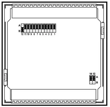
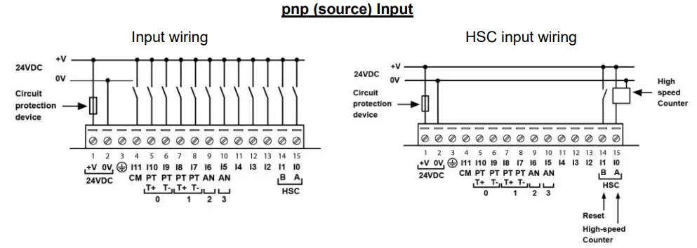
Input Jumper Settings
The tables below show how to set a specific jumper to change input functionality. To access the I/O jumpers, you must open the controller according to the instructions beginning on page 13.
- Incompatible jumper settings and wiring connections may seriously damage the controller.

| Digital Inputs 0-11: Set Type | |||
| Set to | JP12 (all Inputs) | ||
| npn (sink) | A | ||
| pnp (source)* | B | ||
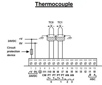
| Inputs 7/8: Set Type – Digital or RTD/TC #1 | |||
| Set to | JP1 | JP2 | JP3 |
| Digital* | A | A | A |
| Thermocouple | B | B | B |
| PT100 | B | A | B |
| Inputs 9/10: Set Type – Digital or RTD/TC #0 | |||
| Set to | JP5 | JP6 | JP7 |
| Digital* | A | A | A |
| Thermocouple | B | B | B |
| PT100 | B | A | B |
| Input 11: Set Type – Digital or CM for PT100 | |||
| Set to | JP11 | ||
| Digital* | A | ||
| CM for PT100 | B | ||
| Input 5: Set Type – Digital or Analog #3 | |||
| Set to | JP4 | JP10 | |
| Digital* | A | A | |
| Voltage | B | A | |
| Current | B | B | |
| Input 6: Set Type – Digital or Analog #2 | |||
| Set to | JP8 | JP9 | |
| Digital* | A | A | |
| Voltage | B | A | |
| Current | B | B | |
| Analog Output 0: Set to Voltage/Current | ||
| Set to | JP13 | |
| Voltage* | A | |
| Current | B | |
| Analog Output 1: Set to Voltage/Current | ||
| Set to | JP14 | |
| Voltage* | A | |
| Current | B | |
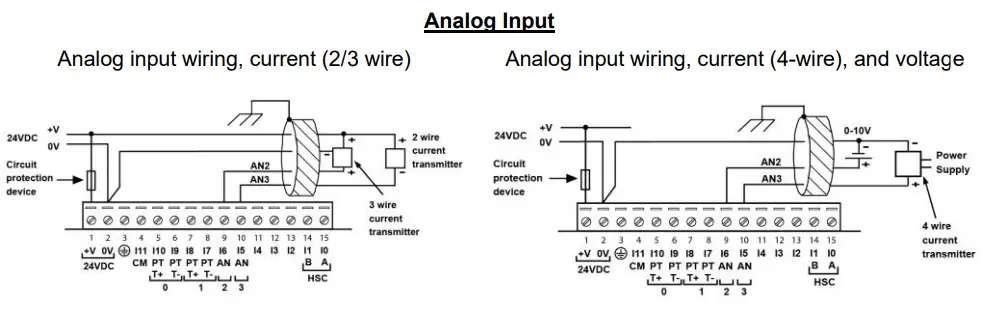
- Shields should be connected at the signal’s source.
- The 0V signal of the analog input must be connected to the controller’s 0V.
- Thermocouple 0: use Input 9 as negative input and 10 as positive.
- Thermocouple 1: use Input 7 as negative input and 8 as positive.
| Type | Temp. Range | Wire Color | |
| ANSI (USA) | BS1843 (UK) | ||
| mV | -5 to 56mV | ||
| B | 200 to 1820˚C (300 to 3276˚F) | +Grey -Red | +None -Blue |
| E | -200 to 750˚C (-328 to 1382˚F) | +Violet -Red | +Brown -Blue |
| J | -200 to 760˚C (-328 to 1400˚F) | +White -Red | +Yellow -Blue |
| K | -200 to 1250˚C (-328 to 2282˚F) | +Yellow -Red | +Brown -Blue |
| N | -200 to 1300˚C (-328 to 2372˚F) | +Orange -Red | +Orange -Blue |
| R | 0 to 1768˚C (32 to 3214˚F) | +Black -Red | +White -Blue |
| S | 0 to 1768˚C (32 to 3214˚F) | +Black -Red | +White -Blue |
| T | -200 to 400˚C (-328 to 752˚F) | +Blue -Red | +White -Blue |
RTD
- PT100 (Sensor 0): use Input 9 and 10, related to CM signal.
- PT100 (Sensor 1): use Input 7 and 8, related to CM signal.
- 4 wire PT100 can be used by leaving one of the sensor leads unconnected.


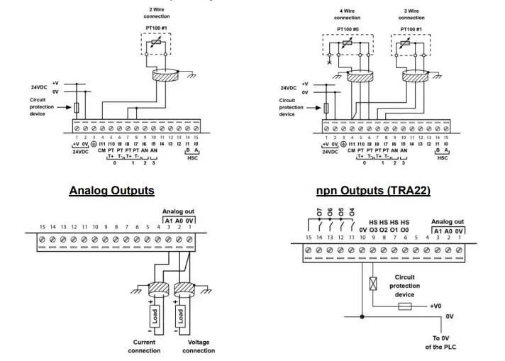
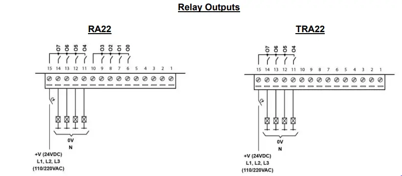
Relay Outputs
Increasing Contact Life Span
To increase the life span of the relay output contacts and protect the device from potential damage by reverse EMF, connect: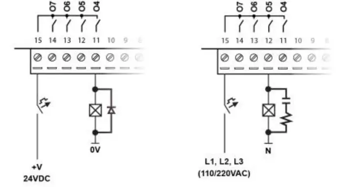
- A clamping diode in parallel with each inductive DC load
- An RC snubber circuit in parallel with each inductive AC load
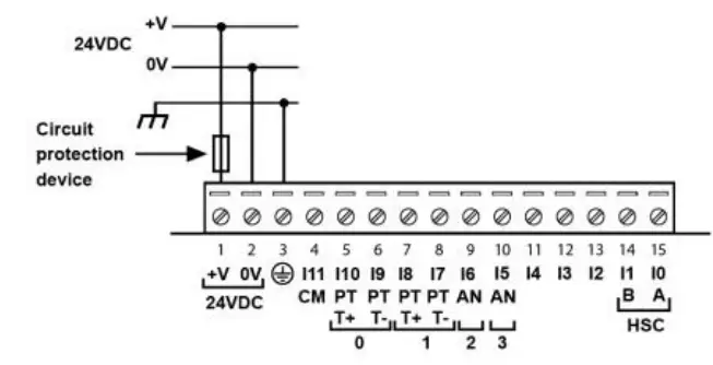
Power Supply
The controller requires an external 24VDC power supply.
- The power supply must include double insulation. Outputs must be rated as SELV/PELV/Class2/Limited Power.

- Use separate wires to connect the functional earth line (pin 3) and the 0V line (pin 2) to the system earth ground.
- Install an external circuit breaker. Guard against short-circuiting in external wiring.
- Double-check all wiring before turning on the power supply.
- Do not connect either the ‘Neutral’ or ‘Line’ signal of the 110/220VAC to device’s 0V pin
- In the event of voltage fluctuations or non-conformity to voltage power supply specifications, connect the device to a regulated power supply.
Earthing the PLC+HMI
To maximize system performance, avoid electromagnetic interference by:
- Mounting the controller on a metal panel.
- Connect each common and ground connection directly to the earth ground of your system.
- For ground wiring uses the shortest and thickest possible wire.
Communication
- V130/ V130J/V350J
These models comprise a built-in RS232/RS485 serial port (Port 1) - V430J/ V350/V350J
These models comprise built-in ports: 1 USB and 1 RS232/RS485 (Port 1).
Note that physically connecting a PC to the controller via USB suspends RS232/RS485 communications via Port 1. When the PC is disconnected, RS232/RS485 resumes.
RS232/RS485 Port
| § Turn off power before making communications connections. | |
| Caution | § Always use the appropriate port adapters. |
| Caution | § Signals are related to the controller’s 0V; the same 0V is used by the power supply. § The serial port is not isolated. If the controller is used with a non-isolated external device, avoid potential voltage that exceeds ± 10V. |
- Use RS232 to download programs from a PC, and to communicate with serial devices and applications, such as SCADA.
- Use RS485 to create a multi-drop network containing up to 32 devices.
Pinouts
The pinouts below show the PLC port signals.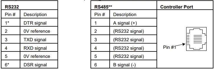 * Standard programming cables do not provide connection points for pins 1 and 6.
** When a port is adapted to RS485, Pin 1 (DTR) is used for signal A, and Pin 6 (DSR) signal is used for signal B.
Note that it is possible to establish a PC to PLC connection using RS232 even when the PLC is set to RS485 (this eliminates the need to open the controller to set jumpers).
To do so, remove the RS485 connector (pins 1 & 6) from the PLC and connect a standard RS232 programming cable.
Note that this is possible only if DTR and DSR signals of RS232 are not used (which is the standard case).
Setting RS232/RS485 Communication Parameters, V130/V350/V130J/V350J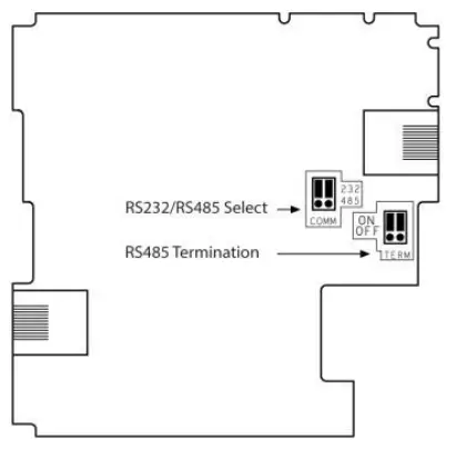 This port may be set to either RS232 or RS485 via jumper.
The accompanying figure shows the jumper factory default settings.
These jumpers may be used to:
- Set communications to RS485, by setting both COMM jumpers to ‘485’.
- Set RS485 termination, by setting both TERM jumpers to ‘OFF’.
To access the jumpers, you must open the controller according to the instructions on page 13.
Setting RS232/RS485 Communication Parameters, V430J
This port may be set to either RS232 or RS485 via DIP switches:
The table shows the DIP switches factory default settings. Use the table to adapt the settings.
| Switch Settings | ||||||
| 1 | 2 | 3 | 4 | 5 | 6 | |
| RS232* | ON | OFF | OFF | ON | OFF | OFF |
| RS485 | OFF | ON | ON | OFF | OFF | OFF |
| RS485 with termination** | OFF | ON | ON | OFF | ON | ON |
USB Port
| Caution | § The USB port is not isolated. Make sure that the PC and the controller are grounded to same potential. |
| The USB port may be used for programming, OS download, and PC access. | |
Opening the Controller
- Before performing these actions, touch a grounded object to discharge any electrostatic charge.
- Avoid touching the PCB board directly. Hold the PCB board by its connectors.
- Turn off the power supply, disconnect, and dismount the controller.
- The back cover of the controller comprises 4 screws, located in the corners. Remove the screws, and pull off the back cover.
Changing I/O Settings
After opening the controller and exposing the I/O board, you can change the jumper settings according to the table shown above.
Changing Communication Settings (V130/V350/V130J/V350J Only)
- To access the communication jumpers, hold the I/O PCB board by its top and bottom connectors and steadily pull the board off.
- Locate the jumpers, and then change the settings as required, according to the jumpers’ settings shown on page 12.
Closing the Controller
- Gently replace the board. Make certain that the pins fit correctly into their matching receptacle. Do not force the board into place; doing so may damage the controller.
- Replace the back cover of the controller and fasten the corner screws.
Note that you must replace the back cover securely before powering up the controller.
Vision™PLC+HMI
V130-33-TRA22/V130-J-TRA22
V350-35-TRA22/V350-J-TRA22
V430-J-TRA22
Technical Specifications
Order Information
| Order Information | |
| Item | |
| V130-33-TRA22 | PLC with Classic panel, Monochrome display 2.4″ |
| V130-J-TRA22 | PLC with Flat panel, Monochrome display 2.4″ |
| V350-35-TRA22 | PLC with Classic panel, Color touch display 3.5’’ |
| V350-J-TRA22 | PLC with Flat panel, Color touch display 3.5’’ |
| V430-J-TRA22 | PLC with Flat panel, Color touch display 4.3’’ |
| You can find additional information, such as wiring diagrams, in the product’s installation guide located in the Technical Library at www.unitronics.com. | |
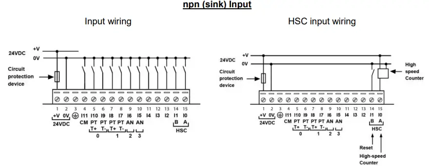
| Digital Inputs | ||
| Number of inputs | 12. See note 2 | |
| Input type | See note 2 | |
| Galvanic isolation | None | |
| Nominal input voltage | 24VDC | |
| Input Voltage | Normal digital input | High Speed Input. See Note 3 |
| pnp (source) | 0-5VDC for Logic ‘0’ 17-28.8VDC for Logic ‘1’ | 0-3VDC for Logic ‘0’ 20.4-28.8VDC for Logic ‘1’ |
| npn (sink) | 17-28.8VDC for Logic ‘0’ 0-5VDC for Logic ‘1 | 20.4-28.8VDC for Logic ‘0’ 0-3VDC for Logic ‘1 |
| Input Current | I0, I1: 5.4mA@24VDC I2-I11: 3.7mA@24VDC | |
| Input impedance | I0, I1: 4.5KΩ I2-I11: 6.5KΩ | |
| Response Time | 10ms typical, when used as normal digital input | |
| Input Cable length | ||
| Normal digital Input | Up to 100 meters | |
High Speed Input
Up to 50 meters, shielded, see Frequency table below
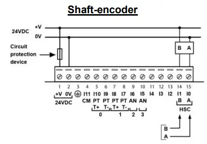
| High speed inputs | Specifications below apply when wired as HSC/shaft-encoder. See Note 2 | |
| Frequency, HSC | ||
| Driver type | pnp/npn | Push-pull |
| Cable length (max.) | ||
| 10m | 95kHz maximum | 200kHz maximum |
| 25m | 50kHz maximum | 200kHz maximum |
| 50m | 25kHz maximum | 200kHz maximum |
| Frequency, Shaft-encoder | ||
| Driver type | pnp/npn | Push-pull |
| Cable length (max.) | ||
| 10m | 35kHz maximum | 100kHz maximum |
| 25m | 18kHz maximum | 100kHz maximum |
| 50m | 10kHz maximum | 100kHz maximum |
| Duty cycle | 40-60% | |
| Resolution | 32-bit | |
| Notes: | ||
| 2. V130/V350/V130J/V350J/V430J-TRA22 models comprise a total of 12 inputs. All 12 inputs may be used as digital inputs. They may be wired in a group via a single jumper as either npn or pnp. In addition, according to jumper settings and appropriate wiring: – Inputs 5 and 6 can function as either digital or analog inputs. – Input 0 can function as a high-speed counter, as part of a shaft-encoder, or as normal digital inputs. – Input 1 can function as either counter reset, normal digital input, or as part of a shaft-encoder. – If input 0 is set as a high-speed counter (without reset), input 1 can function as a normal digital input. – Inputs 7-8 and 9-10 can function as digital, thermocouple, or PT100 inputs; input 11 can also serve as the CM signal for PT100. 3. If you configure an input as high-speed, you can use an end-device that comprises push-pull drive type. In this case, the high-speed input voltage ratings for npn/pnp apply. | ||
| Order Information | |
| Item | |
| V130-33-TRA22 | PLC with Classic panel, Monochrome display 2.4″ |
| V130-J-TRA22 | PLC with Flat panel, Monochrome display 2.4″ |
| V350-35-TRA22 | PLC with Classic panel, Color touch display 3.5’’ |
| V350-J-TRA22 | PLC with Flat panel, Color touch display 3.5’’ |
| V430-J-TRA22 | PLC with Flat panel, Color touch display 4.3’’ |
| You can find additional information, such as wiring diagrams, in the product’s installation guide located in the Technical Library at www.unitronics.com. | |
Conversion times are accumulative and depend on the total number of analog inputs configured. For example, if only one analog input (fast mode) is configured, the conversion time will be 30ms; however, if two analog (normal mode) and two RTD inputs are configured, the conversion time will be 100ms + 100ms + 300ms + 300ms = 800ms.
The analog value can indicate faults as shown below:
| Value: 12-bit | Value: 14-bit | Possible Cause |
| -1 | -1 | Deviates slightly below the input range |
| 4096 | 16384 | Deviates slightly above the input range |
| 32767 | 32767 | Deviates greatly above or below the input range |
| RTD Inputs | ||
| RTD Type | PT100 | |
| Temperature coefficient a | 0.00385/0.00392 | |
| Input range | -200 to 600°C/-328 to 1100°F. 1 to 320Ω. | |
| Isolation | None | |
| Conversion method | Voltage to frequency | |
| Resolution | 0.1°C/0.1°F | |
| Conversion time | 300ms minimum per channel. See Note 4 above | |
| Input impedance | >10MΩ | |
| Auxillary current for PT100 | 150μA typical | |
| Full-scale error | ±0.4% | |
| Linearity error | ±0.04% | |
| Status indication | Yes. See Note 6 | |
| Cable length | Up to 50 meters, shielded | |
| Notes: | ||
| 6. The analog value can indicate faults as shown below: | ||
| Value | Possible Cause | |
| 32767 | Sensor is not connected to input, or value exceeds permissible range | |
| -32767 | Sensor is short-circuited | |
| Thermocouple Inputs | |
| Input range | See Note 7 |
| Isolation | None |
| Conversion method | Voltage to frequency |
| Resolution | 0.1°C/ 0.1°F maximum |
| Conversion time | 100ms minimum per channel. See Note 4 above |
| Input impedance | >10MΩ |
| Cold junction compensation | Local, automatic |
| Cold junction compensation error | ±1.5°C/±2.7°F maximum |
| Absolute maximum rating | ±0.6VDC |
| Full-scale error | ±0.4% |
| Linearity error | ±0.04% |
| Warm-up time | ½ hour typically, ±1°C/±1.8°F repeatability |
| Status indication | Yes. See Note 6 above |
Notes:
The analog value can indicate faults as shown below:
- Value
Possible Cause - 32767
Sensor is not connected to input, or value exceeds permissible range - -32767
Sensor is short-circuited
| Thermocouple Inputs | |
| Input range | See Note 7 |
| Isolation | None |
| Conversion method | Voltage to frequency |
| Resolution | 0.1°C/ 0.1°F maximum |
| Conversion time | 100ms minimum per channel. See Note 4 above |
| Input impedance | >10MΩ |
| Cold junction compensation | Local, automatic |
| Cold junction compensation error | ±1.5°C/±2.7°F maximum |
| Absolute maximum rating | ±0.6VDC |
| Full-scale error | ±0.4% |
| Linearity error | ±0.04% |
| Warm-up time | ½ hour typically, ±1°C/±1.8°F repeatability |
| Status indication | Yes. See Note 6 above |
Notes:
The device can also measure voltage within the range of -5 to 56mV, at a resolution of 0.01mV. The device can also measure raw value frequency at a resolution of 14-bits (16384). Input ranges are shown in the following table:
| Digital Outputs | |
| Number of outputs | 4 relay. See Note 8 |
| Output type | SPST-NO (Form A) |
| Isolation | By relay |
| Type of relay | Tyco PCN-124D3MHZ or compatible |
| Output current (resistive load) | 3A maximum per output 8A maximum total per common |
| Rated voltage | 250VAC / 30VDC |
| Minimum load | 1mA, 5VDC |
| Life expectancy | 100k operations at maximum load |
| Response time | 10ms (typical) |
| Contact protection | External precautions required (see Increasing Contact Life Span in the product’s Installation Guide) |
| Notes: | |
| 8. Outputs 4, 5, 6, and 7 share a common signal. | |
| Transistor Outputs | |
| Number of outputs | 4 npn (sink). See Note 9 |
| Output type | N-MOSFET, (open drain) |
| Galvanic Isolation | None |
| Maximum output current (resistive load) | 100mA per output |
| Rated voltage | 24VDC |
| Maximum delay OFF to ON | 1ms |
| Maximum delay ON to OFF | 10ms |
| HSO freq. range with resistive load | 5Hz-200kHz (at maximum load resistance of 1.5kΩ) |
| Maximum ON voltage drop | 1VDC |
| Short-circuit protection | None |
| Voltage range | 3.5V to 28.8VDC |
| Notes: | |
| 9. Outputs 0, 1, 2 and 3 share a common 0V signal. The 0V signal of the output must be connected to the controller’s 0V. | |
| Analog Outputs | |
| Number of outputs | 2 |
| Output range | 0-10V, 4-20mA. See Note 10 |
| Resolution | 12-bit (4096 units) |
| Conversion time | Both outputs are updated per scan |
| Load impedance | 1kΩ minimum—voltage 500Ω maximum—current |
| Galvanic isolation | None |
| Linearity error | ±0.1% |
| Operational error limits | ±0.2% |
| Notes: | |
| 10. Note that the range of each I/O is defined by wiring, jumper settings, and within the controller’s software. | |
| Graphic Display Screen | |||
| Item | V130-TRA22 V130J-TRA22 | V350-TRA22 V350J-TRA22 | V430J-TRA22 |
| LCD Type | STN, LCD display | TFT, LCD display | TFT, LCD display |
| Illumination backlight | White LED | White LED | White LED |
| Display resolution | 128×64 pixels | 320×240 pixels | 480×272 pixels |
| Viewing area | 2.4″ | 3.5″ | 4.3″ |
| Colors | Monochrome | 65,536 (16-bit) | 65,536 (16-bit) |
| Screen Contrast | Via software (Store value to SI 7, values range: 0 to 100%) | Fixed | Fixed |
| Touchscreen | None | Resistive, analog | Resistive, analog |
| ‘Touch’ indication | None | Via buzzer | Via buzzer |
| Screen brightness control | Via software (Store value to SI 9, 0 = Off, 1 = On) | Via software (Store value to SI 9, values range: 0 to 100%) | |
| Virtual Keypad | None | Displays virtual keyboard when the application requires data entry. | |
| Keypad | |||
| Item | V130-TRA22 V130J-TRA22 | V350-TRA22 V350J-TRA22 | V430J-TRA22 |
| Number of keys | 20 keys,including 10 user-labeled keys | 5 programmable function keys | |
| Key type | Metal dome, sealed membrane switch | ||
| Slides | Slides may be installed in the operating panel faceplate to custom-label the keys. Refer to V130 Keypad Slides.pdf. A complete set of blank slides is available by separate order | Slides may be installed in the operating panel faceplate to custom-label the keys. Refer to V350 Keypad Slides.pdf. Two sets of slides are supplied with the controller: one set of arrow keys, and one blank set. | None |
| Program | |||
| Item | V130-TRA22 V130J-TRA22 | V350-TRA22 V350J-TRA22 | V430J-TRA22 |
| Memory size | |||
| Application Logic | 512KB | 1MB | 1MB |
| Images | 128KB | 6MB | 12MB |
| Fonts | 128KB | 512KB | 512KB |
| Item | V130-TRA22 V130J-TRA22 | V350-TRA22 V350J-TRA22 V430J-TRA22 | ||
| Memory Bits | 4096 | 8192 | MB | Bit (coil) |
| Memory Integers | 2048 | 4096 | MI | 16-bit signed/unsigned |
| Long Integers | 256 | 512 | ML | 32-bit signed/unsigned |
| Double Word | 64 | 256 | DW | 32-bit unsigned |
| Memory Floats | 24 | 64 | MF | 32-bit signed/unsigned |
| Fast Bits | 1024 | 1024 | XB | Fast Bits (coil) – not retained |
| Fast Integers | 512 | 512 | XI | 16 bit signed/unsigned (fast, not retained) |
| Fast Long Integers | 256 | 256 | XL | 32 bit signed/unsigned (fast, not retained) |
| Fast Double Word | 64 | 64 | XDW | 32 bit unsigned (fast, not retained) |
| Timers | 192 | 384 | T | Res. 10 ms; max 99h, 59 min, 59.99s |
| Counters | 24 | 32 | C | 32-bit |
| Removable Memory | |
| Micro SD card | Compatible with standard SD and SDHC; up to 32GB store datalogs, Alarms, Trends, Data Tables, backup Ladder, HMI, and OS. See Note 11 |
| Notes: | |
| 11.User must format via Unitronics SD tools utility. | |
| Communication Ports | |
| Port 1 | 1 channel, RS232/RS485 and USB device (V430/V350/V350J only). See Note 12 |
| Galvanic isolation | No |
| Baud rate | 300 to 115200 bps |
| RS232 | |
| Input voltage | ±20VDC absolute maximum |
| Cable length | 15m maximum (50’) |
| RS485 | |
| Input voltage | -7 to +12VDC differential maximum |
| Cable type | Shielded twisted pair, in compliance with EIA 485 |
| Cable length | 1200m maximum (4000’) |
| Nodes | Up to 32 |
| USB device (V430/V350/V350J only) | |
| Port type | Mini-B, See Note 14 |
| Specification | USB 2.0 complaint; full speed |
| Cable | USB 2.0 complaint; up to 3m |
| Port 2 (optional) | See Note 13 |
| CANbus (optional) | See Note 13 |
| Notes: |
| 12. This model is supplied with a serial port: RS232/RS485 (Port 1). The standard is set to either RS232 or RS485 according to jumper settings. Refer to the product’s Installation Guide. 13. The user may order and install one or both of the following modules: – An additional port (Port 2). Available port types: RS232/RS485 isolated/non-isolated, Ethernet – A CANbus port Port module documentation is available on the Unitronics website. 14. Note that physically connecting a PC to the controller via USB suspends RS232/RS485 communications via Port 1. When the PC is disconnected, RS232/RS485 resumes. |
| I/O Expansion | |
| Additional I/Os may be added. Configurations vary according to module. Supports digital, high-speed, analog, weight and temperature measurement I/Os. | |
| Local | Via I/O Expansion Port. Integrate up to 8 I/O Expansion Modules comprising up to 128 additional I/Os. Adapter required (P.N. EX-A2X). |
| Remote | Via CANbus port. Connect up to 60 adapters to a distance of 1000 meters from controller; and up to 8 I/O expansion modules to each adapter (up to a total of 512 I/Os). Adapter required (P.N. EX-RC1). |
| Miscellaneous | |
| Clock (RTC) | Real-time clock functions (date and time) |
| Battery back-up | 7 years typical at 25°C, battery back-up for RTC and system data, including variable data |
| Battery replacement | Yes. Coin-type 3V, lithium battery, CR2450 |
| Dimensions | ||||
| Item | V130-TRA22 V130J-TRA22 | V350-TRA22 V350J-TRA22 | V430J-TRA22 | |
| Size | Vxxx | 109 x 114.1 x 68mm (4.29 x 4.49 x 2.67”). See Note 15 | 109 x 114.1 x 68mm (4.29 x 4.49 x 2.67”). See Note 15 | |
| Vxxx-J | 109 x 114.1 x 66mm (4.92 x 4.49 x 2.59”). See Note 15 | 109 x 114.1 x 66mm (4.92 x 4.49 x 2.59”). See Note 15 | 136 x 105.1 x 61.3mm (5.35 x 4.13 x 2.41”). See Note 15 | |
| Weight | 300g (10.58 oz) | 325g (11.46 oz) | 355g (12.52 oz) | |
| Notes: |
| 15. For exact dimensions, refer to the product’s Installation Guide. |
| Environment | |
| Operational temperature | 0 to 50ºC (32 to 122ºF) |
| Storage temperature | -20 to 60ºC (-4 to 140ºF) |
| Relative Humidity (RH) | 10% to 95% (non-condensing) |
| Mounting method | Panel mounted (IP65/66/NEMA4X) DIN-rail mounted (IP20/NEMA1) |
| Operating Altitude | 2000m (6562 ft) |
| Shock | IEC 60068-2-27, 15G, 11ms duration |
| Vibration | IEC 60068-2-6, 5Hz to 8.4Hz, 3.5mm constant amplitude, 8.4Hz to 150Hz, 1G acceleration. |
| The information in this document reflects products at the date of printing. Unitronics reserves the right, subject to all applicable laws, at any time, at its sole discretion, and without notice, to discontinue or change the features, designs, materials and other specifications of its products, and to either permanently or temporarily withdraw any of the forgoing from the market. All information in this document is provided “as is” without warranty of any kind, either expressed or implied, including but not limited to any implied warranties of merchantability, fitness for a particular purpose, or non-infringement. Unitronics assumes no responsibility for errors or omissions in the information presented in this document. In no event shall Unitronics be liable for any special, incidental, indirect or consequential damages of any kind, or any damages whatsoever arising out of or in connection with the use or performance of this information. The tradenames, trademarks, logos and service marks presented in this document, including their design, are the property of Unitronics (1989) (R”G) Ltd. or other third parties and you are not permitted to use them without the prior written consent of Unitronics or such third party as may own them |
| UG_V130_350_430-RA22 11/22 |


