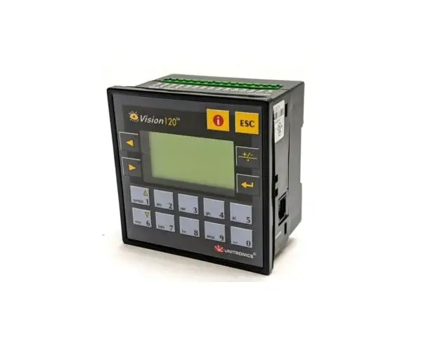
UNITRONICS V120-22-T1 PLC Controllers
General Description
The products listed above are micro-PLC+HMIs, rugged programmable logic controllers that comprise built-in operating panels.
Detailed Installation Guides containing the I/O wiring diagrams for these models, technical specifications, and additional documentation are located in the Technical Library in the Unitronics website: https://unitronicsplc.com/support-technical-library/
Alert Symbols and General Restrictions
When any of the following symbols appear, read the associated information carefully.
| Symbol | Meaning | Description |
| Danger | The identified danger causes physical and property damage. | |
| Warning | The identified danger could cause physical and property damage. | |
| Caution | Caution | Use caution. |
- Before using this product, the user must read and understand this document.
- All examples and diagrams are intended to aid understanding, and do not guarantee operation.
Unitronics accepts no responsibility for actual use of this product based on these examples. - Please dispose of this product according to local and national standards and regulations.
- Only qualified service personnel should open this device or carry out repairs.
 Failure to comply with appropriate safety guidelines can cause severe injury or property damage.
- Do not attempt to use this device with parameters that exceed permissible levels.
 To avoid damaging the system, do not connect/disconnect the device when power is on.
Environmental Considerations
- Do not install in areas with: excessive or conductive dust, corrosive or flammable gas, moisture or rain, excessive heat, regular impact shocks or excessive vibration, in accordance with the standards given in the product’s technical specification sheet.
- Do not place in water or let water leak onto the unit.
- Do not allow debris to fall inside the unit during installation.
- Ventilation: 10mm space required between controller’s top/bottom edges & enclosure walls.
- Install at maximum distance from high-voltage cables and power equipment.
Mounting
Note that figures are for illustrative purposes only.
Dimensions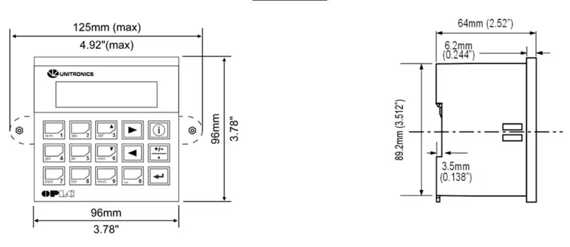
| Model | Cut-out | View area |
| V120 | 92×92 mm (3.622”x3.622”) | 57.5×30.5mm (2.26″x1.2″) |
| M91 | 92×92 mm (3.622”x3.622”) | 62×15.7mm (2.44″x0.61″) |
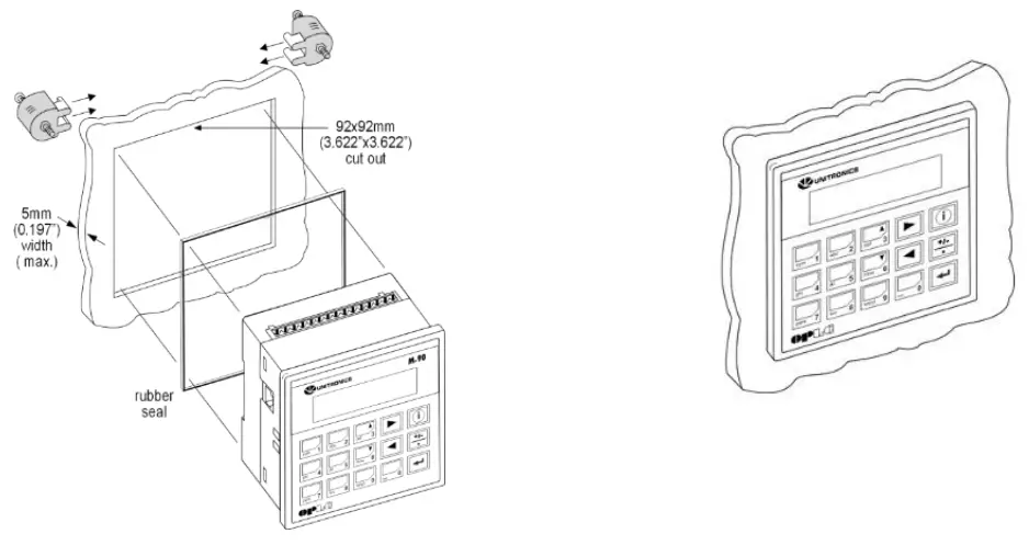
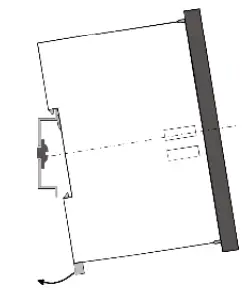
Panel Mounting
Before you begin, note that the mounting panel cannot be more than 5 mm thick.
- Make a panel cut-out of the appropriate size:
- Slide the controller into the cut-out, ensuring that the rubber seal is in place.
- Push the mounting brackets into their slots on the sides of the panel as shown in the figure below.
- Tighten the bracket’s screws against the panel. Hold the bracket securely against the unit while tightening the screw.
- When properly mounted, the controller is squarely situated in the panel cut-out as shown in the accompanying figures.

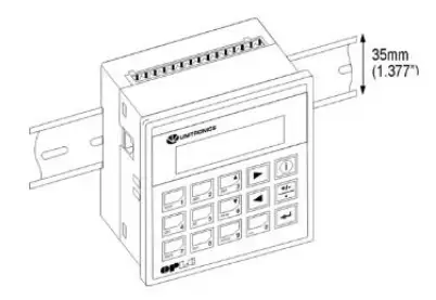
DIN-rail Mounting
- Snap the controller onto the DIN rail as shown in the figure to the right.

- When properly mounted, the controller is squarely situated on the DIN-rail as shown in the figure to the right.

Wiring
- Do not touch live wires.
- This equipment is designed to operate only in SELV/PELV/Class 2/Limited Power environments.
- All power supplies in the system must include double insulation. Power supply outputs must be rated as SELV/PELV/Class 2/Limited Power.
- Do not connect either the ‘Neutral or ‘Line’ signal of the 110/220VAC to device’s 0V pin.
- All wiring activities should be performed while power is OFF.
- Use over-current protection, such as a fuse or circuit breaker, to avoid excessive currents into the power supply connection point.
- Unused points should not be connected (unless otherwise specified). Ignoring this directive may damage the device.
- Double-check all wiring before turning on the power supply.
Caution
- To avoid damaging the wire, do not exceed a maximum torque of:
- Controllers offering a terminal block with pitch of 5mm: 0.5 N·m (5 kgf·cm).
- Controllers offering a terminal block with pitch of 3.81mm f 0.2 N·m (2 kgf·cm).
- Do not use tin, solder, or any substance on stripped wire that might cause the wire strand to break.
- Install at maximum distance from high-voltage cables and power equipment
Wiring Procedure
Use crimp terminals for wiring;
- Controllers offering a terminal block with pitch of 5mm: 26-12 AWG wire (0.13 mm2 –3.31 mm2).
- Controllers offering a terminal block with pitch of 3.81mm: 26-16 AWG wire (0.13 mm2 – 1.31 mm2).
- Strip the wire to a length of 7±0.5mm (0.270–0.300“).
- Unscrew the terminal to its widest position before inserting a wire.
- Insert the wire completely into the terminal to ensure a proper connection.
- Tighten enough to keep the wire from pulling free.
Wiring Guidelines
- Use separate wiring ducts for each of the following groups:
- Group 1: Low voltage I/O and supply lines, communication lines.
- Group 2: High voltage Lines, Low voltage noisy lines like motor driver outputs.
Separate these groups by at least 10cm (4″). If this is not possible, cross the ducts at a 90˚angle.
- For proper system operation, all 0V points in the system should be connected to the system 0V supply rail.
- Product-specific documentation must be fully read and understood before performing any wiring.
Allow for voltage drop and noise interference with input lines used over an extended distance.
Use wire that is properly sized for the load.
Earthing the product
To maximize system performance, avoid electromagnetic interference as follows:
- Use a metal cabinet.
- Connect the 0V and functional ground points (if exist) directly to the earth ground of the system.
- Use the shortest, less than 1m (3.3 ft.) and thickest, 2.08mm² (14AWG) min, wires possible.
UL Compliance
The following section is relevant to Unitronics’ products that are listed with the UL.
The following models: V120-22-T1, V120-22-T2C, V120-22-UA2, V120-22-UN2, M91-2-R1, M91-2-R2C, M91-2-R6, M91-2-R6C, M91-2-T1, M91-2-T2C, M91-2-UA2, M91-2-UN2 are UL listed for Hazardous Locations.
The following models: V120-22-R1, V120-22-R2C, V120-22-R34, V120-22-R6, V120-22-R6C, V120- 22-RA22, V120-22-T1, V120-22-T2C, V120-22-T38, V120-22-UA2, V120-22-UN2, M91-2-FL1, M91-2- PZ1, M91-2-R1, M91-2-R2, M91-2-R2C, M91-2-R34, M91-2-R6, M91-2-R6C, M91-2-RA22, M91-2-T1, M91-2-T2C, M91-2-T38, M91-2-TC2, M91-2-UA2, M91-2-UN2, M91-2-ZK, M91-T4-FL1, M91-T4-PZ1, M91-T4-R1, M91-T4-R2, M91-T4-R2C, M91-T4-R34, M91-T4-R6, M91-T4-R6C, M91-T4-RA22, M91-T4- T1, M91-T4-T2C, M91-T4-T38, M91-T4-TC2, M91-T4-UA2, M91-T4-UN2, M91-T4-ZK are UL listed for Ordinary Location.
For models from series M91, that include “T4” in the Model name, Suitable for mounting on the flat surface of Type 4X enclosure.
For examples: M91-T4-R6
UL Ordinary Location
In order to meet the UL ordinary location standard, panel-mount this device on the flat surface of Type 1 or 4 X enclosures
UL Ratings, Programmable Controllers for Use in Hazardous Locations, Class I, Division 2, Groups A, B, C and D
These Release Notes relate to all Unitronics products that bear the UL symbols used to mark products that have been approved for use in hazardous locations, Class I, Division 2, Groups A, B, C and D.
Caution
- This equipment is suitable for use in Class I, Division 2, Groups A, B, C and D, or Nonhazardous locations only.
- Input and output wiring must be in accordance with Class I, Division 2 wiring methods and in accordance with the authority having jurisdiction.
- WARNING—Explosion Hazard—substitution of components may impair suitability for Class I, Division 2.
- WARNING – EXPLOSION HAZARD – Do not connect or disconnect equipment unless power has been switched off or the area is known to be non-hazardous.
- WARNING – Exposure to some chemicals may degrade the sealing properties of material used in Relays.
- This equipment must be installed using wiring methods as required for Class I, Division 2 as per the NEC and/or CEC.
Panel-Mounting
For programmable controllers that can be mounted also on panel, in order to meet the UL Haz Loc standard, panel-mount this device on the flat surface of Type 1 or Type 4X enclosures.
Relay Output Resistance Ratings
The products listed below contain relay outputs:
Programmable controllers, Models: M91-2-R1, M91-2-R2C,M91-2-R6C, M91-2-R6
- When these specific products are used in hazardous locations, they are rated at 3A res.
- when these specific products are used in non-hazardous environmental conditions, they are rated at 5A res, as given in the product’s specifications.
Temperature Ranges
Programmable Logic Controllers, Models, M91-2-R1, M91-2-R2C, M91-2-R6C.
- When these specific products are used in hazardous locations, they may be used only within a temperature range of 0-40ºC (32- 104ºF).
- When these specific products are used in non-hazardous environmental conditions, they function within the range of 0-50ºC (32- 122ºF) given in the product’s specifications.
Removing / Replacing the battery
When a product has been installed with a battery, do not remove or replace the battery unless the power has been switched off, or the area is known to be non-hazardous.
Please note that it is recommended to back up all data retained in RAM, in order to avoid losing data when changing the battery while the power is switched off. Date and time information will also need to be reset after the procedure.
Graphic Operator Panel & Programmable Logic Controller
J.2/24VDC, 12 pnp/npn digital inputs, 2 high-speed counter/shaft encoder inputs, 12 transistor outputs, 1/0 expansion port, 2 RS232/RS485 ports
| Power supply | 12VDC or 24VDC 10.2VDC to 28.8VDC with less than 10% ripple |
| Permissible range | |
| Maximum current consumption | 130mA@24VDC (pnp inputs) 230mA@24VDC (npn inputs) 240mA@12VDC (pnp inputs) 280mAn12VDC (npn inputs) |
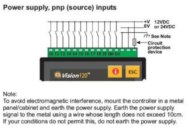
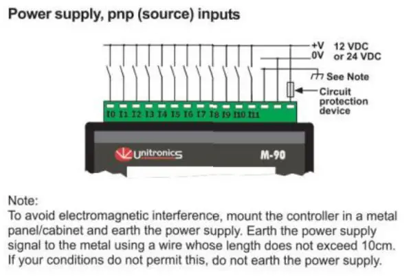
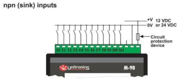
| Digital Inputs | 12 pnp (source) or npn (sink) inputs. See Note 1. |
| Nominal input voltage | 12VDC or 24VDC. See Notes 2 and 3. |
| Input voltages for pnp (source): For 12VDC For 24VDC | 0-3VDC for Logic ‘0’ 8-15.6VDC for Logic ‘1’ 0-5VDC for Logic ‘0’ 17-28.8VDC for Logic ‘1’ |
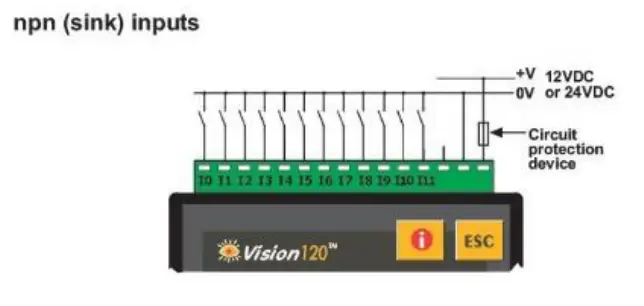
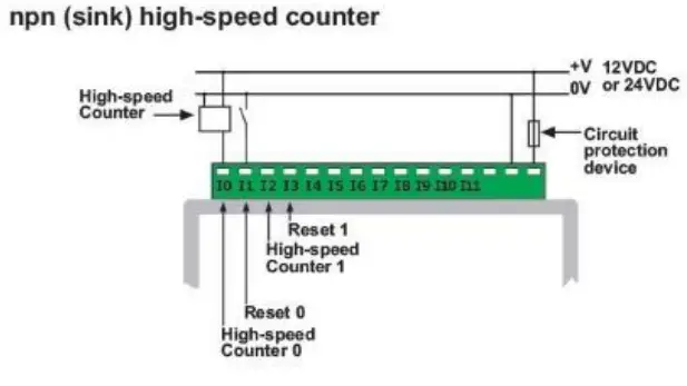
| Input voltages for npn (sink): For 12VDC For 24VDC | 8-15.6VDC/<1.2mA for Logic ‘0’ 0-3VDC/>3mA for Logic ‘1’ 17-28.8VDC/<2mA for Logic ‘0’ 0-5VDC/>6mA for Logic ‘1’ |
| Input current | 4mA@12VDC 8mAA24VDC |
| Input impedance | 3KS2 |
| Response time (except high-speed inputs) | 10mS typical |
| Galvanic isolation | None |
| Input cable length | Up to 100 meters, unshielded |
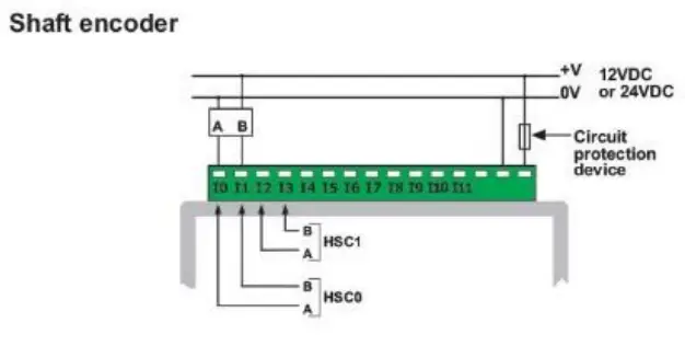
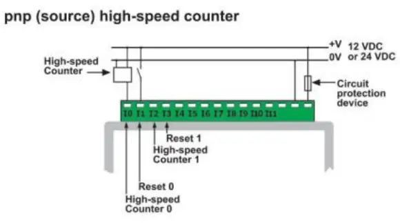
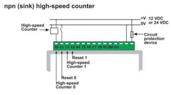
| High-speed counter | Specifications below apply when inputs are wired for use as a highspeed counter input/shaft encoder. See Notes 4 and 5. |
| Resolution | 32-bit |
| Input frequency | 10kHz max. |
| Minimum pulse | 40ws |
Notes:
- All 12 inputs can be set to pnp (soll’ce) or npn (sink) via a single jumper and appropriate wiring.
- AH 12 inputs can fundk>n in 12 voe or 24 VOC; set via a single jumper and appropriate wiring.
- npn (sink) inputs use voltage supplied from the controller’s power supply.
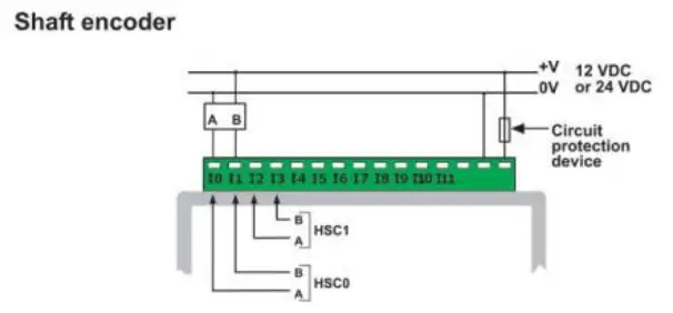
- Inputs #0 and #2 can each fl.rlction as either high-speed counter or as part d a shaft enooder. In each case. high-speed input specifications apply. When used as a oorma1 digital input, normal input specifications apply.
- Inputs #1 and #3 can each function as either counter reset, or as a normal digital input: in either case, specifications are those of a normal digital input.
These inputs may also be used as part of a shaft encoder. In this case, high-speed input specifications apply.

![]() Warnings:
Warnings:
- Unused pins should not be connected. Ignoring this directive may damage the controller.
- Improper use of this product may severely damage the controller.
- Refer to the controller’s User Guide regarding wiring considerations.
- Before using this product, it is the responsibility of the user to read the product’s User Guide and all accompanying documentation.
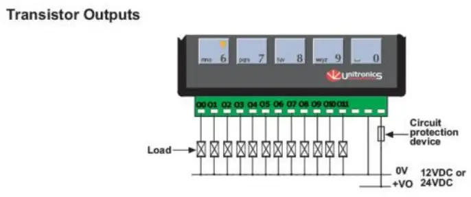
| Digital outputs | 12 pnp (source) outputs 12VDC or 24VDC |
| Output type | P-MOSFET (open drain) |
| Isolation | None |
| Output current | 0.5A max. Total current: 3A max. |
| Max. frequency for normal outputs | 50Hz (resistive load) 0.5Hz (inductive load) |
| High speed output maximum frequency | 2kHz (resistive load) See Note 1. |
| Short circuit protection | Yes |
| Short indication | by software |
| On voltage drop | 0.5VDC maximum |
| Power supply for outputs | |
| Operating voltage | 10.2 to 28.8VDC |
| Nominal operating voltage | 12VDC or 24VDC |
Note:
1. Output #0 and Output #1 may be used as high-speed outputs.
| Graphic Display | STN LCD display |
| Illumination backlight | LED, yellow-green, software-controlled |
| Display resolution | 128×64 pixels |
| Keypad | |
| Number of keys | Sealed membrane |
| 16 | |
| Program | |
| Application memory | |
| 448K | |
| Memory Bits (coils) | 2048 |
| Memory Integers (registers) | 1600 |
| Long Integers (32 bit) | 256 |
| Double Word (32 bit unsigned) | 64 |
| Floats | 24 |
| Timers | 192 |
| Counters | 24 |
| Data Tables | 120K (RAM)/ 64K (FLASH) |
| HMI displays | Up to 255 |
| Execution time | 0.8ps for bit operations |
| RS232/RS485 serial ports | Used for: • Application Download/Upload • Application Testing (Debug) • Connect to GSM or standard telephone modem: – Send/receive SMS messages – Remote access programming • RS485 Networking
|
| RS232 (see note) 2 ports | |
| Galvanic isolation | None |
| Voltage limits | t20V |
| RS485 (see note) | 2 ports |
| Input voltage | -7 to +12V differential max. |
| Cable type | Shielded twisted pair, in compliance with EIA RS485 |
| Galvanic isolation | None |
| Baud rate | 110 — 57600 bps |
| Nodes | Up to 32 |
Note:
RS232/RS465 is determined by Jumper settings and wiring.
Refer to the controller’s User Guide regarding communications.
| I/O expansion port: Up to 128 additional I/Os, including digital & analog I/Os, RTD and more. | |
| Miscellaneous Clock (RTC) | |
| Real-time clock functions (Date and time). | |
| Battery back-up | 7 years typical battery back-up for RTC and system data. |
| Battery | Coin type, 3V lithium battery, CR2450 |
| Weight | 280g (9.87 oz.) |
| Operational temperature | 0 to 50°C (32 to 122°F) |
| Storage temperature | -20 to 60°C (-4 to 140°F) |
| Relative Humidity (RH) | 5% to 95% (non-condensingL |
| Mounting method | DIN-rail mounted (IP2O/NEMA1) Panel mounted (IP65/NEMA4X) |
Notes:
- All 12 inputs can be set to pnp (source) or npn (sink) via a single jumper and appropriate wiring.
- All 12 inputs can function in 12 VDC or 24 VDC; set via a single jumper and appropriate wiring.
- npn {sink) inputs use voltage supplied from the controller’s power supply.
- Inputs #0 and #2 can each function as either high-speed counter or as part of a shaft encoder. In each case, high-speed input specifications apply. When used as a normal digital input, normal input specifications apply.
- Inputs #1 and #3 can each function as either counter reset, or as a normal digital input; In either case, specifications are those of a normal digital input.
These inputs may also be used as part of a shaft encoder.
In this case, high-speed input specifications apply.
![]() Warnings:
Warnings:
- Unused pins should not be connected. Ignoring this directive may damage the controller.
- Improper use of this product may severely damage the controller.
- Refer to the controller’s User Guide regarding wiring considerations.
- Before using this product, it Is the responsibility of the user to read the product’s User Guide and all accompanying documentation.
| Digital outputs | 12 pnp (source) outputs 12VDC or 24VDC |
| Output type | P MOSFET (open drain) |
| Isolation | None |
| Output current | 0.5A max. Total current: 3A max. |
| Max. frequency for normal outputs | 50Hz (resistive load) 0.5Hz (inductive load) |
| High speed output maximum frequency | 2kHz (resistive load) See Note 1. |
| Short circuit protection | Yes |
| Short indication | by software |
| On voltage drop | 0.5VDC maximum |
| Power supply for outputs Operating voltage Nominal operating voltage | 10.2 to 28.8VDC 12VDC or 24VDC |
Note:
1. Output #0 and Output #1 may be used as high-speed outputs.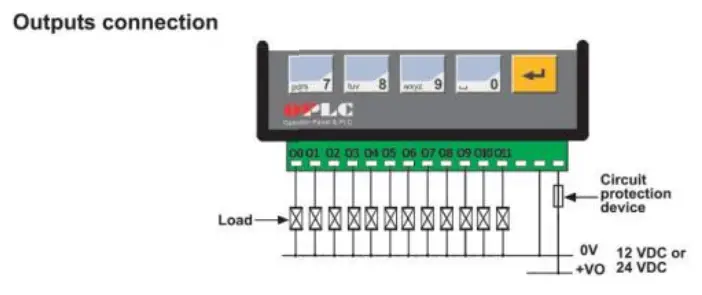
| Display | STN, LCD display |
| Illumination | LED yellow-green backlight |
| Display size | 2 lines, 16 characters long |
| Character size | 5 x 8 matrix, 2.95 x 5.55mm |
| Keypad | Sealed membrane |
| Number of keys | 15 |
| PLC program | |
| Ladder Code Memory (virtual) | 36K |
| Memory Bits (coils) | 256 |
| Memory Integers (Registers) | 256 |
| Timers | 64 |
| Execution time | 12psec. for bit operations |
| Database | 1024 integers (indirect access) |
| HMI displays | 80 user-designed displays |
| HMI variables | 64 HMI variables are available to conditionally display and modify text, numbers, dates, times & timer values. The user can also create a list of up to 120 variable text displays, totaling up to 2K. |
| RS232 (see note) | 1 port |
| Galvanic isolation | None |
| Voltage limits | t20V |
| RS485 (see note) | 1 port |
| Input voltage | -7 to +12V differential max. |
| Cable type | Shielded twisted pair, in compliance with EIA RS485 |
| Galvanic isolation | None |
| Baud rate | 110 — 57600 bps |
| Nodes | Up to 32 |
| Note: RS232/RS485 is determined by jumper settings and wiring as described in the document ‘M91 RS485 Port Settings’ packaged with the controller. | |
| I/O ex ansionsort: Up to 64 additional I/Os, including digital & analog I/Os, RTD and more. | |
| Miscellaneous Clock (RTC) | |
| Real-time clock functions (Date and lime). | |
| Battery back-up | 7 years typical battery back-up for RTC and system data. |
| Weight | 266g (9.37 oz.) |
| Operational temperature | 0 to 50°C (32 to 122°F) |
| Storage temperature | -20 to 60°C (-4 to 140°F) |
| Relative Humidity (RH) | 5% to 95% (non-condensing) |
| Mounting method | DIN-rail mounted (IP20/NEMA1) Panel mounted (IP65/NEMA4X) |
Jumper Settings
The tables below show how to set a specific jumper to change the functionality of the inputs.
To open the controller and access the jumpers, refer to the directions at the end of these specifications.
Important:
Incompatible jumper settings and wiring connections may severely damage the controller.
JPS
Input type (for all digital inputs)
| To use as | JP8 |
| npn (sink) | A |
| pnp (source)” | B |
JP9
Input voltage (for all digital inputs)
| To use as | JP9 |
| 12VDC | A |
| 24VDC* | B |
·Default factory setting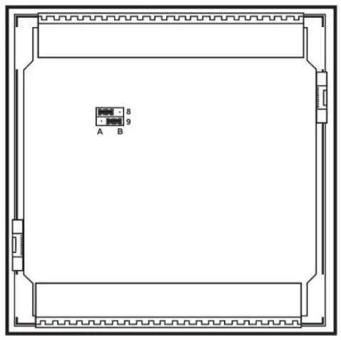
In this figure, the jumper settings will cause the inputs to function as npn, 24VDC digital inputs
Communication Ports
Note that different controller models offer different serial and CANbus communication options. To see which options are relevant, check your controller’s technical specifications.
- Turn off power before making communications connections.
Caution
- Note that the serial ports are not isolated.
- Signals are related to the controller’s 0V; the same 0V is used by the power supply.
- Always use the appropriate port adapters.
Serial Communications
This series comprises 2 serial port can be set to either RS232 or RS485 according to jumper settings. By default, the ports are set to RS232.
Use RS232 to download programs from a PC, and to communicate with serial devices and applications, such as SCADA.
Use RS485 to create a multi-drop network containing up to 32 devices.
Caution
- The serial ports are not isolated. If the controller is used with a non isolated external device, avoid potential voltage that exceeds ± 10V.
Pinouts
The pinouts below show the signals between the adapter and port.
| RS232 | |
| Pin # | Description |
| 1* | DTR signal |
| 2 | 0V reference |
| 3 | TXD signal |
| 4 | RXD signal |
| 5 | 0V reference |
| 6* | DSR signal* |
| RS485 | Controller Port | |
| Pin # | Description | 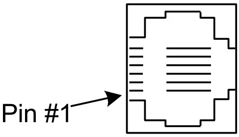 |
| 1 | A signal (+) | |
| 2 | (RS232 signal) | |
| 3 | (RS232 signal) | |
| 4 | (RS232 signal) | |
| 5 | (RS232 signal) | |
| 6 | B signal (-) | |
*Standard programming cables do not provide connection points for pins 1 and 6.
RS232 to RS485: Changing Jumper Settings
- To access the jumpers, open the controller and then remove the module’s PCB board. Before you begin, turn off the power supply, disconnect and dismount the controller.
- When a port is adapted to RS485, Pin 1 (DTR) is used for signal A, and Pin 6 (DSR) signal is used for signal B.
- If a port is set to RS485, and flow signals DTR and DSR are not used, the port can also be used to communicate via RS232; with the appropriate cables and wiring.
- Before performing these actions, touch a grounded object to discharge any electrostatic charge.
- Avoid touching the PCB board directly. Hold the PCB board by its connectors.
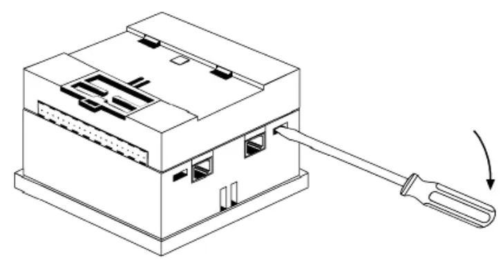
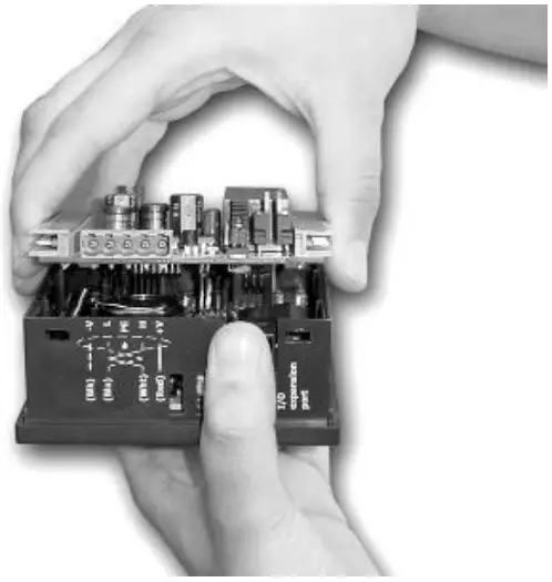
Opening the controller
- Turn power off before opening the controller.
- Locate the 4 slots on the sides of the controller.
- Using the blade of a flat-bladed screwdriver, gently pry off the back of the controller.

- Gently remove the top PCB board:
a. Use one hand to hold the top-most PCB board by its top and bottom connectors.
b. With the other hand, grasp the controller, while keeping hold of the serial ports; this will keep the bottom board from being removed together with the top board.
c. Steadily pull the top board off.
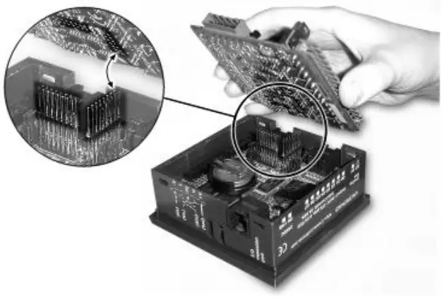
- Locate the jumpers, and then change the jumper settings as required.
- Gently replace the PCB board. Make certain that the pins fit correctly into their matching receptacle.
a. Do not force the board into place; doing so may damage the controller. - Close the controller by snapping the plastic cover back in its place. If the card is placed correctly, the cover will snap on easily.

M91: RS232/RS485 Jumper Settings
| RS232/RS485 Jumper Setting | ||
| To use as | Jumper 1 | Jumper 2 |
| RS232* | A | A |
| RS485 | B | B |
| RS485 Termination | ||
| Termination | Jumper 3 | Jumper 4 |
| ON* | A | A |
| OFF | B | B |
*Default factory setting.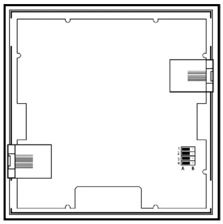
V120: RS232/RS485 Jumper Settings
| Jumper Settings | |||
| Jumper | RS232* | RS485 | |
| COM 1 | 1 | A | B |
| 2 | A | B | |
| COM 2 | 5 | A | B |
| 6 | A | B | |
| RS485 Termination | ||
| Jumper | ON* | OFF |
| 3 | A | B |
| 4 | A | B |
| 7 | A | B |
| 8 | A | B |
*Default factory setting.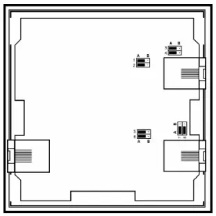
CANbus
These controllers comprise a CANbus port. Use this to create a decentralized control network of up to 63 controllers, using either Unitronics’ proprietary CANbus protocol or CANopen.
The CANbus port is galvanically isolated.
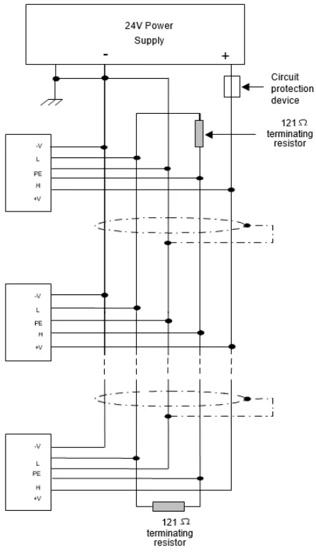
CANbus Wiring
Use twisted-pair cable. DeviceNet® thick shielded twisted pair cable is recommended.
Network terminators: These are supplied with the controller. Place terminators at each end of the CANbus network.
Resistance must be set to 1%, 1210, 1/4W.
Connect ground signal to the earth at only one point, near the power supply.
The network power supply need not be at the end of the network
CANbus Connector
The information in this document reflects products at the date of printing. Unitronics reserves the right, subject to all applicable laws, at any time, at its sole discretion, and without notice, to discontinue or change the features, designs, materials and other specifications of its products, and to either permanently or temporarily withdraw any of the forgoing from the market.
All information in this document is provided “as is” without warranty of any kind, either expressed or implied, including but not limited to any implied warranties of merchantability, fitness for a particular purpose, or non-infringement. Unitronics assumes no responsibility for errors or omissions in the information presented in this document. In no event shall Unitronics be liable for any special, incidental, indirect or consequential damages of any kind, or any damages whatsoever arising out of or in connection with the use or performance of this information.
The tradenames, trademarks, logos and service marks presented in this document, including their design, are the property of Unitronics (1989) (R”G) Ltd. or other third parties and you are not permitted to use them without the prior written consent of Unitronics or such third party as may own them


