velleman VM142 Mini PIC-PLC Application Module
 WARNINGS
- All repairs should be executed by qualified technicians.
- Avoid the installation of the module in locations with standing or running water or excessive humidity. Indoor use only !
SAFETY INSTRUCTIONS
- Handle the module gently and carefully. Dropping it can damage the circuit board and case.
- Never exceed the protection limit values indicated in the specifications.
- As safety requirement vary, please check with your local authorities.
- No objects or liquids should be allowed to penetrate the housing.
- Disconnect the module from the AC power before connecting new devices.
- Wipe the device with a dry and clean cloth. Do not use detergents or other liquids that may damage the housing.
- Keep the device away from children.
- Facilitate the operation of the device by familiarizing yourself with its adjustments and indications.
- Velleman modules are not suitable for use or as part of life support systems, or systems that might create hazardous situations of kind.
Repair under warranty is only possible with date and proof of purchase.
WARRANTY
This product is guaranteed against defects in components and construction from the moment it is purchased and for a period of TWO YEAR starting from the date of sale. This guarantee is only valid if the unit is submitted together with the original purchase invoice. VELLEMAN components Ltd limits its responsibility to the reparation of defects or, as VELLEMAN components Ltd deems necessary, to the replacement or reparation of defective components. Costs and risks connected to the transport, removal or place-ment of the product, or any other costs directly or indirectly connected to the repair, will not be reimbursed by VELLEMAN components Ltd. VELLEMAN components Ltd will not be held responsible for any damages caused by the malfunctioning of a unit.
SPECIFICATIONS & FEATURES
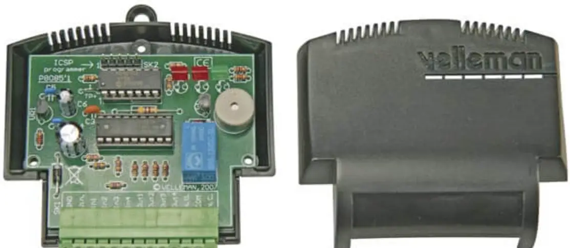
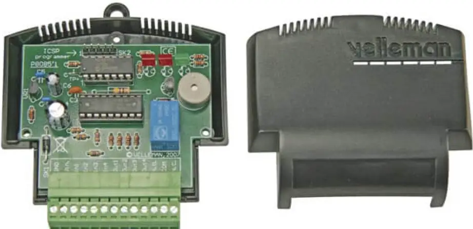
Description
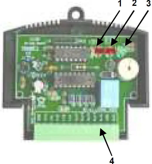
- Diagnose LED
- Relay control LED
- Power supply indication
- Terminal block
- See also connection diagram on page 7…9
The VM142 is equipped with a popular 8-bit Microchip® microcontroller. The PCB layout is designed in such way to include 4 buffered inputs and outputs, a potential-free relay output and an onboard buzzer. The PIC™ microcontroller is freely programmable and the software can be developed in Assembler, C or even special versions of Basic, Pascal,… Note that a certain level of experience in PIC™ microcontrollers and their programming is required.
Visit www.velleman.be and download software examples.
FEATURES
- 9 freely programmable inputs and outputs (4 inputs, 5 outputs)
- onboard Microchip® PIC16F630 microcontroller
- LED indication for power supply and relay output
- 1 freely programmable LED indication
- onboard buzzer
- output transistor can be easily replaced
- ICSP™ connector for direct controller programming
You need a PIC™ programmer supporting the PIC16F630, e.g. VM134 (K8076), for programming this module.
SPECIFICATIONS
- Power supply: 12VDC / 100mA
- 4 NPN transistor inputs / 4 NPN transistor outputs
- 1 relay output with NO/NC contact (24VDC / 2A)
- MCU speed: fixed 4MHz internal oscillator
- Input signal voltage: 5 – 24VDC, max. 10mA
- max. transistor output current: 100mA each
- dimension: 80 x 70 x 25mm
DESCRIPTIONS OF THE TERMINAL BLOCK
GND-Vin:  Connect the power supply between connections GND and Vin. Apply a direct voltage of 12V (regulated or not regulated) between the two pins. The electronics of the module are protected against polarity inversion. The 12V DC must be connected to the “Vin” terminal, your ground level to the “GND” terminal.
In1,In2,In3,In4:  These are the four module inputs which can be activated by applying a direct voltage between 5 and 24V. The input impedance is 4.7K.
Note that a voltage exceeding 24V can damage the input transistor.
I/O of the PIC16F630: PORT A
- INPUT1 I/O 3
- INPUT2 I/O 2
- INPUT3 I/O 1
- INPUT4 I/O 0
Programming example :
- BTFSC PORTA,INPUT1
- GOTO INPUT1_NOT_ACTIVE
- GOTO INPUT1_ACTIVE’
- ;Read status of input 1
- ;’1’ Not active
- ;’0’ active (5V … 24VDC)
Out1,Out2,Out3,Out4:  These are the four open-collector type outputs and can each handle a current of max. 100mA.
These transistors are grouped in a transistor array chip, IC2. In case of damage of one of the four inputs or outputs, this IC type ULN2803A can be replaced easily and without soldering.
I/O of the PIC16F630: PORT C
- OUTPUT1 I/O 5
- OUTPUT2 I/O 4
- OUTPUT3 I/O 3
- OUTPUT4 I/O 2
Programming example:
- BSF PORTC,OUTPUT1 ;activate output 1
- BCF PORTC,OUTPUT2 ;deactiva oute tput 2
N.O. – COM – N.C.  Output 5 is voltage-free relay contact with double operation. COM is the common contact, NO is the normally open contact, NC is the normally closed contact
Programming example :
- BSF PORTC,RELAY activate the relay.
- BCF PORTC,RELAY ;deactivate the relay
BUZZER: The built-in buzzer with fixed frequency can be activated and deactivated in your program.
Programming example:
- BSF PORTC,BUZZER ;activate the buzzer
- BCF PORTC,BUZZER ;deactivate the buzzer
Diagnose LED (LD3):  This LED is fixed connected to an I/O of the PIC controller and can be freely programmed. The built-in LED can be activated as follows:
Programming example:
- BSF PORTA,DIAGLED ;activate the led.
- BCF PORTA,DIAGLED ;activate the led.
CONNECTION EXAMPLES
Connection of a load (e.g. Motor) 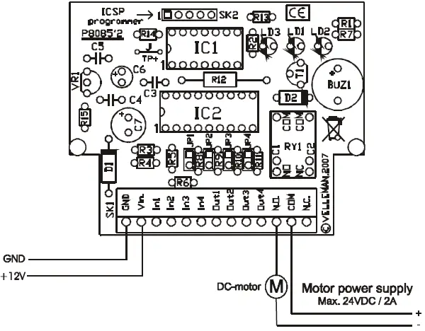 In circuit connection between VM142 and VM134/K8076
 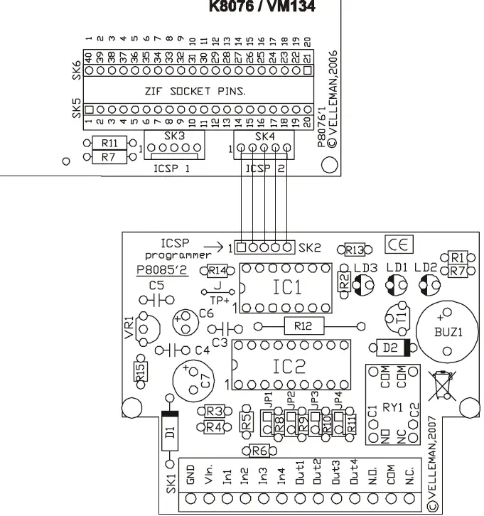 Connection of a relay
 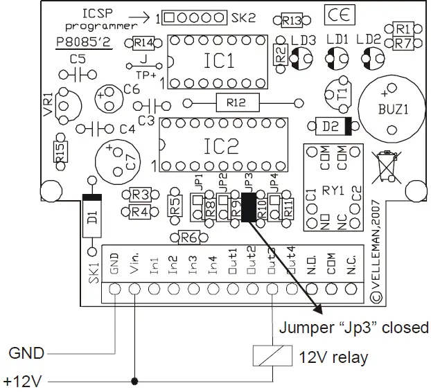 Connection of a switch, push button…
 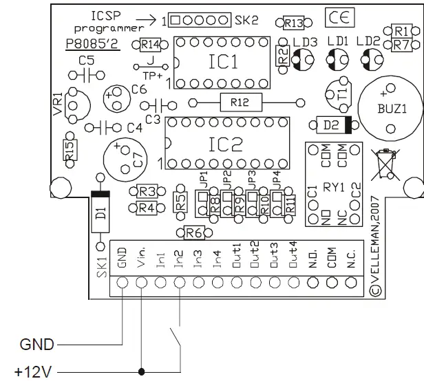 Connection of a LED
 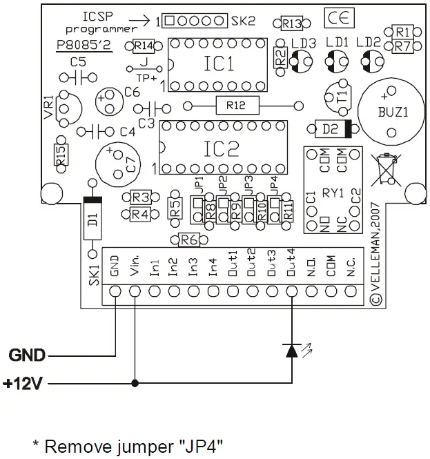 Connection of two or more LEDs to the same output
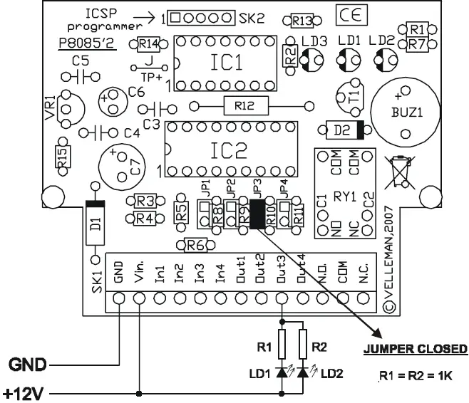
USE
The controller (type PIC16F630) can be programmed in Microchip® PIC™ Assembler and other compilers. The compiler HEX file can be programmed using one of our PIC™ programmers K8048, K8076, VM111, VM134.
The programming method whit the controller remaining onto the PCB is called in-circuit (via the ICSP connector). The controller chip can also be removed out of the IC socket and be inserted into an external programmer.
Using the in-circuit method implies that no input may be activated during the programming process. The output status is also undetermined. Make sure to avoid damages due to an uncontrolled energizing of the relays. Please visit www.velleman.be and download an exemplary program with Assembler source code.
JUMPERS JP1 to JP4:
These jumpers allow you to limit the maximum output current so as to connect a LED directly to the output.
A 1K resistance will be placed in series with the output when you remove the jumper. This value is the value needed to activate a standard LED at a power voltage of 12V. I led = (U – Uled) / Rv (12 – 1.6) / 1000 = 0.0104 10mA.
JP1 Output1, …..
TEST
The VM142 is pre-programmed with a test program allowing you to test all inputs and outputs of the module. The program can be read as follows:
The diagnose LED blinks when applying voltage to the module.
- Activate input 1 Output 1 is energized.
- Activate input 2 Output 2 is energized.
- Activate input 3 Output 3 is energized.
- Activate input 4 Output 4 is energized.
Important environmental information about this product
This symbol on this unit or the package, indicates that disposal of this unit after its lifecycle could harm the environment. Do not dispose the unit as unsorted municipal waste; it should be disposed by a specialized company for recycling. This unit should be returned to your distributor or to a local recycling service. Respect the local environmental rules. If any doubt contact your local authorities about waste disposal rules.


