STMicroelectronics STEVAL-L99615C Evaluation Kit
Introduction
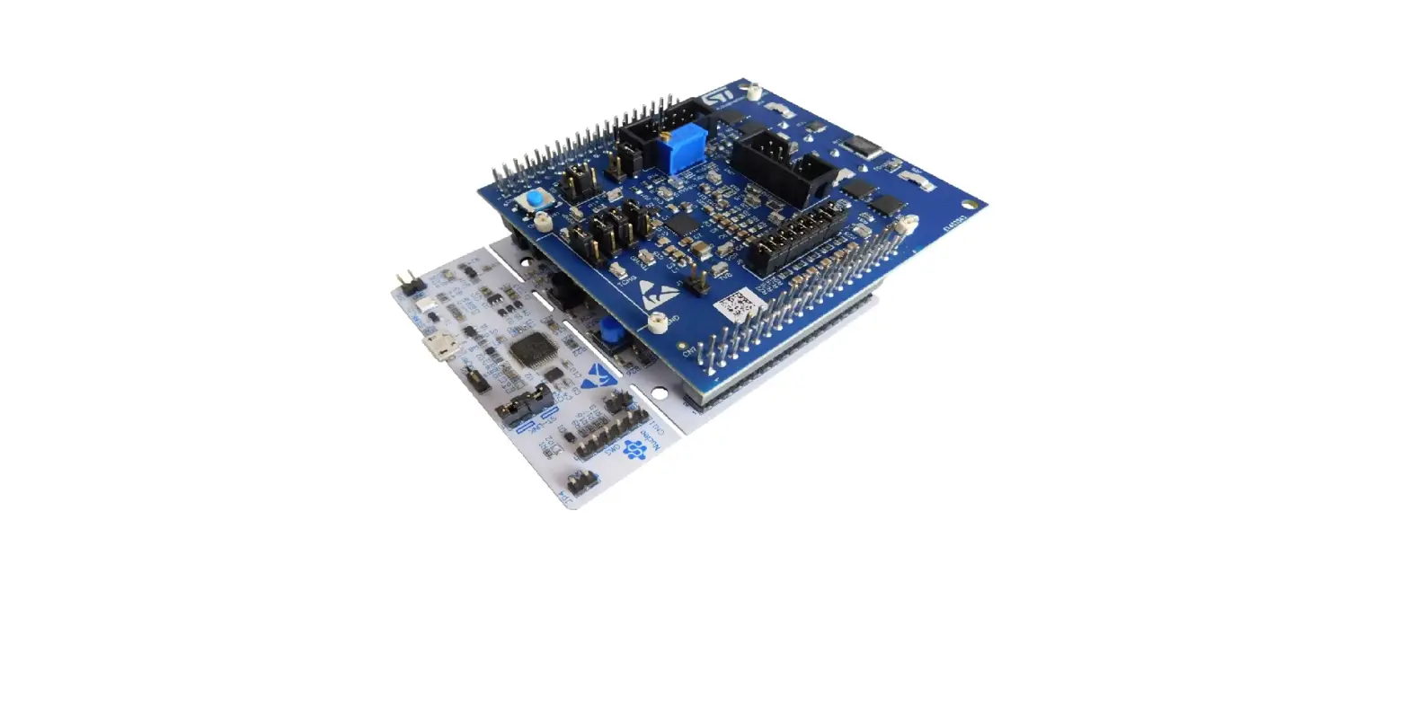
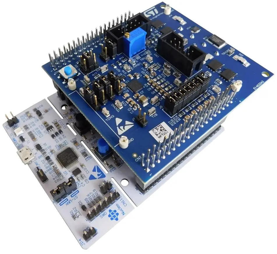
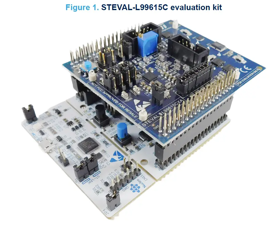
The STEVAL-L99615C is an evaluation kit composed of an expansion board containing the L9961 IC for battery pack monitoring solutions, and the NUCLEO-G071RB STM32 Nucleo-64 development board, aiming to demonstrate the performance and the ease of integration with STMicroelectronics technology for BMS applications.
The kit exploits the characteristics of the L9961, able to monitor up to five Li-Ion battery cells in series configuration, communicating with the STM32G071RB microcontroller, through the I²C interface.
The expansion board has been specifically developed to be stacked on the NUCLEO-G071RB development board through the ST morpho connectors, and embeds a power connector able to connect it to a 5-cell battery pack, or alternatively to an external power supply to emulate the battery pack.
A software package containing a dedicated firmware program for the STM32G071RB microcontroller and a GUI for the PC, has been released to permit users to benefit from the demonstration, looking at the major significant characteristics described by BMS application: cell voltage and stack voltage monitoring, stack current monitoring, temperature conversion via external NTC, OV, and UV thresholds management, etc..
Overview
The STEVAL-L99615C features:
- measurement of cell voltages (3 to 5 cells), with over/undervoltage detection
- measurement of stack voltage, with over/undervoltage detection and plausibility check vs. sum of cells
- measurement of battery pack temperature through an external NTC (emulated by an on-board trimmer) with over/undertemperature detection
- measurement of battery current, with Coulomb counting, overcurrent, and short-circuit in discharge protection
- battery cell balancing supporting up to 70 mA per cell
- dual configurable HS/LS pre-driver for pack relay management
- pack fuse management
- high hot plug robustness
System architecture
The STEVAL-L99615C evaluation kit consists of two subsystems:
- the NUCLEO-G071RB STM32 Nucleo-64 development board embedding the STM32G071RBT6
- the expansion board embedding the L9961 that monitors the battery pack and physically protects the battery-packed application, contributing also to maintain the expected voltages
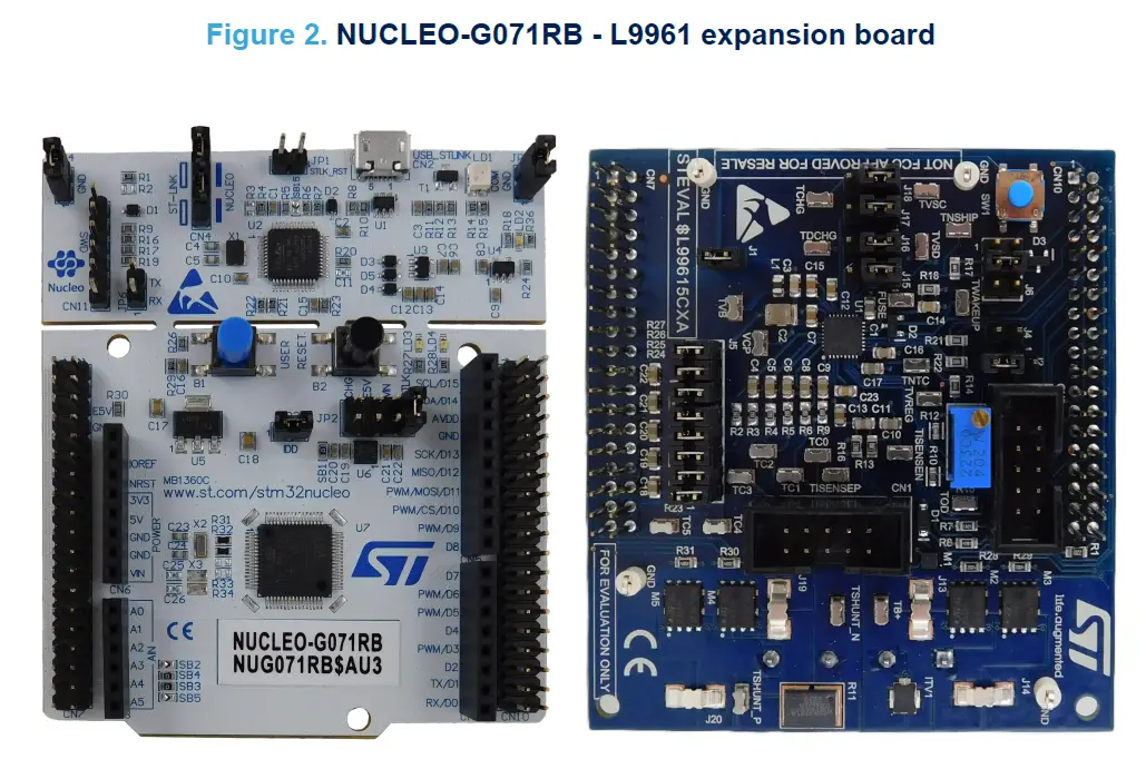
NUCLEO-G071RB development board
The NUCLEO-G071RB STM32 Nucleo-64 development board is based on the high-performance Arm Cortex®-M0+ 32-bit RISC core operating at up to 64 MHz frequency, with 128 KB flash memory and 16 KB SRAM.
The ST morpho headers allow expanding the functionality of the STM32 Nucleo open development platform with a wide choice of specific shields.
The STM32 Nucleo-64 boards do not require any separate probe as they integrate the ST-LINK/V2-1 debugger/programmer. They embed comprehensive, free STM32 software libraries and examples available with the STM32CubeG0 MCU package.
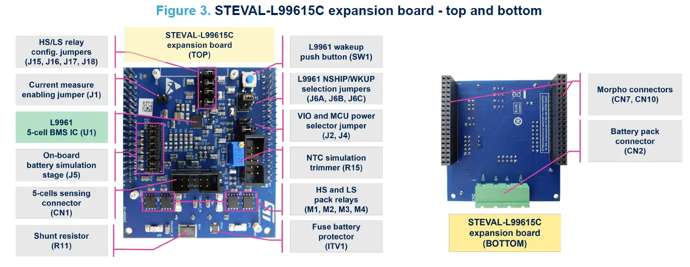
Expansion board
The expansion board hosts the L9961 BMS device, a complete battery pack monitoring, balancing, and protection system for Li-Ion and Li-Polymer cells in 3, 4, or 5 series configurations. The device uses a high precision ADC to provide cell voltage, stack voltage, and temperature conversion via external NTC. Voltage monitoring functions are cyclically performed with a programmable loop time. Stack current is also monitored via a high accuracy CSA, continuously running and also performing Coulomb counting. Cell balancing is available and can be simultaneously activated on all cells. IC configuration and information exchange for SOC/SOH estimation are performed via the I²C peripheral.
The IC also integrates a dual pre-driver programmable in both HS/LS configurations for driving pack relays. The L9961 also implements battery pack fuse protection to prevent fire and explosion hazards. A 3.3 V regulator with a high current capability is available for supplying a pack controller and other external circuitry in both standby and normal operation modes. The IC protects the battery pack against over/undervoltage conditions and monitors for over/undertemperature. It also features protection against overcurrent (both directions) and short-circuit in discharge events. Safety relevant configurations can be stored in the internal NVM to avoid reprogramming the device at each wake-up.
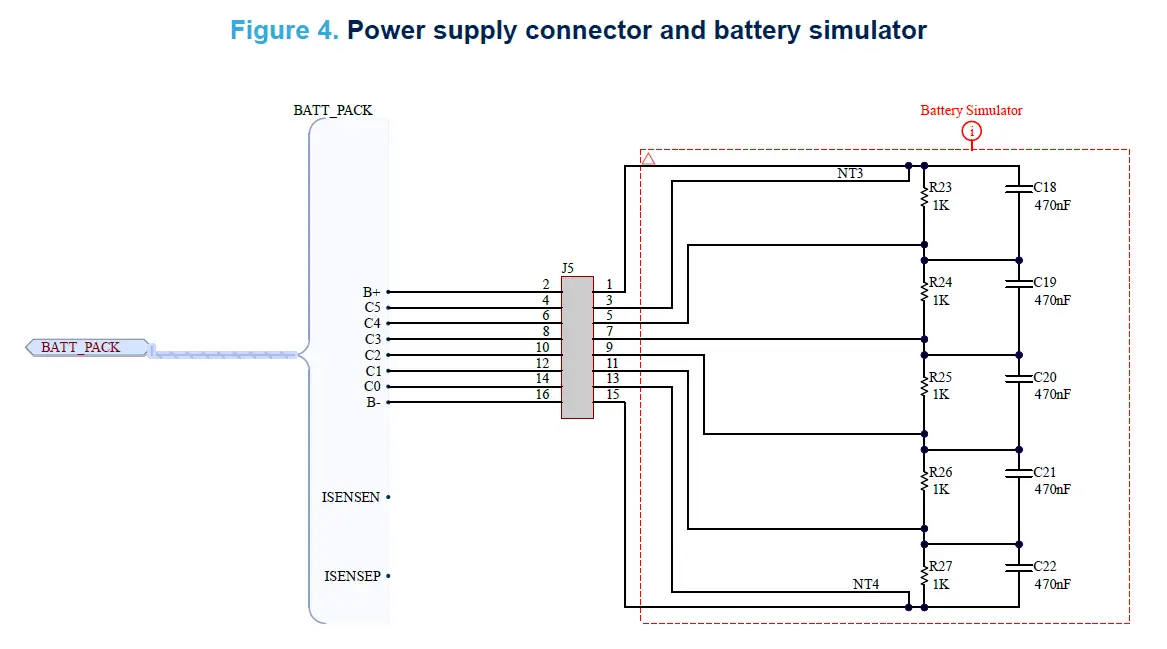
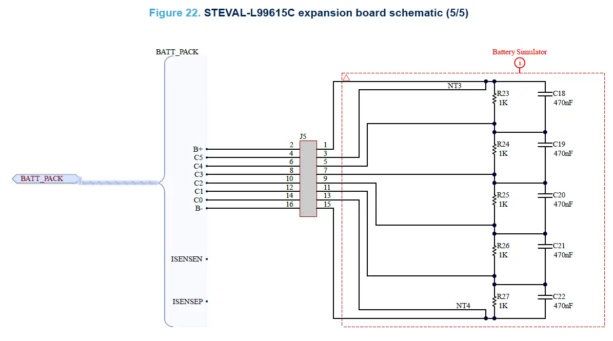
Power supply section
In case a real battery is not available, it is possible to use the battery simulator embedded on the L9961 demo board by installing a J5 jumper and by feeding the L9961 demo board through the CN2 connector (B+ and B-).
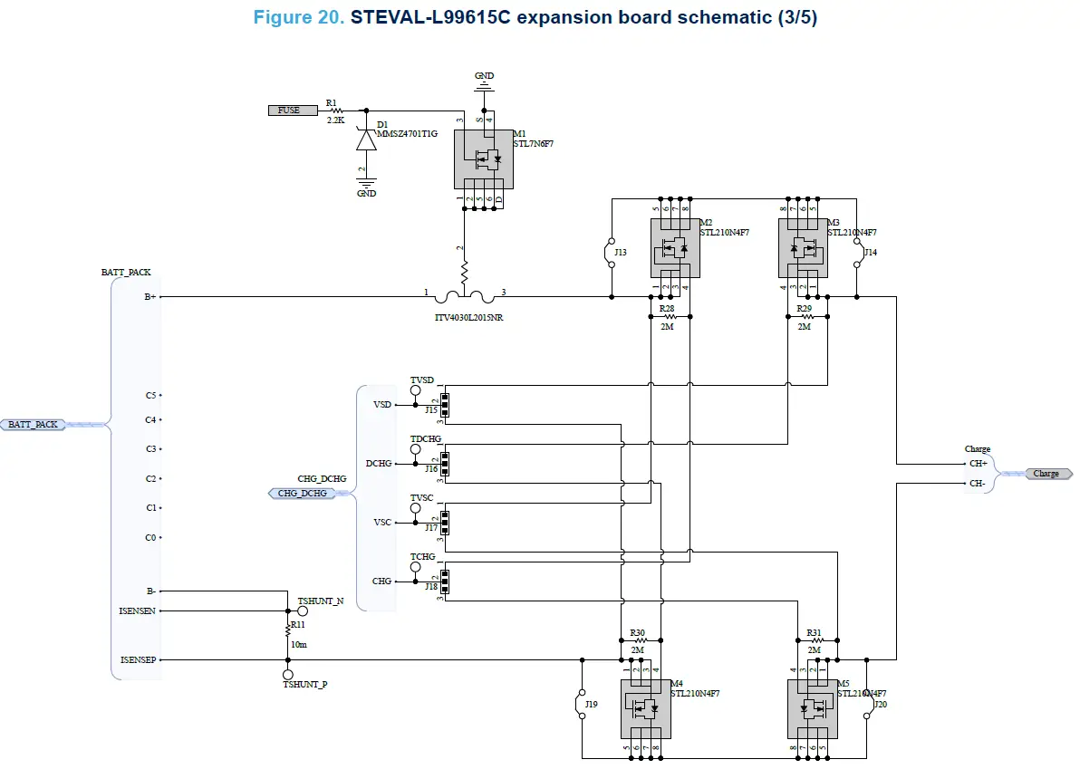
Pack relays stage
The L9961 uses a dual pre-driver stage to manage the external Charge (CHG) and Discharge (DCHG) switches. The pre-driver stage can be configured as high-side or low-side by programming the CHG_HS_LS and DCHG_HS_LS field.
To set the DCHG MOSFET to high-side operation, remove the J13 and J14 jumpers and install a jumper in J15 and J16 position 1-2 or for low-side operation, remove the J19 and J20 jumpers and install a jumper in position 2-3. To set the CHG MOSFET to high-side operation, install a jumper in J17 and J18 position 1-2 or for low-side operation, install a jumper in position 2-3.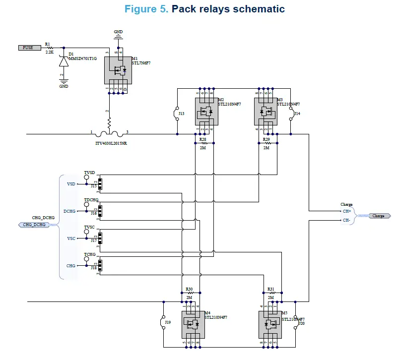
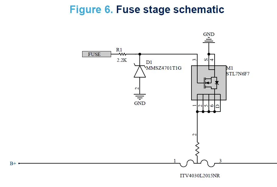
Fuse stage
Under certain conditions classified as permanent failures, the L9961 can be programmed to activate the FUSE pre-driver. An external NMOS can be driven to blow up a fuse connected in series to the battery pack positive terminal.
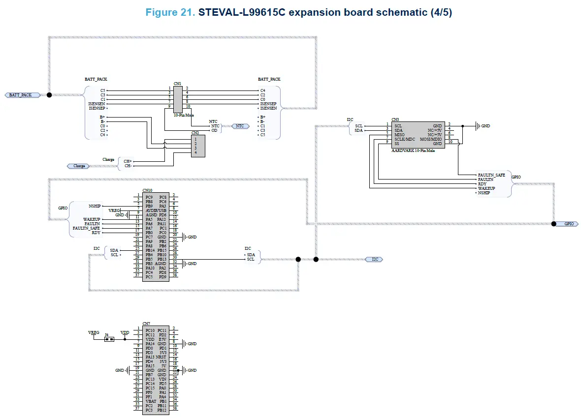
L9961 demo board connectors
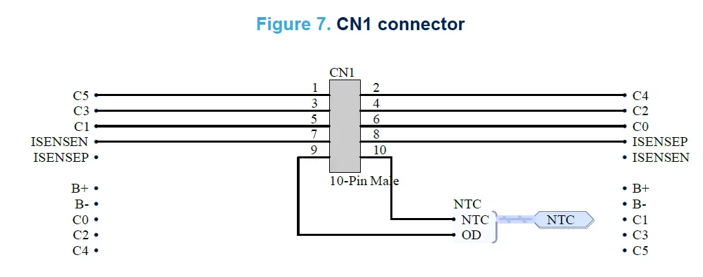
The CN1 is a 10-pin IDC style connector used to route sense signals from the remote 5-cell battery board to the L9961 demo board. The connector contains the Kelvin connections for C0 through C5, the current sense resistors differential voltage, and the NTC voltage, which can be used to route an external NTC and shunt resistor.
If the external Rshunt is used, R11 should be uninstalled and replaced with the new one.
If the external NTC is used, R12 should be removed. Once it has been removed, the user can connect the external resistor between the NTC and OD pins. It is important to polarize the NTC with an external pull-up resistor biased to VREG. For further details regarding the application circuit, please refer to the “Application Information” section in the L9961 datasheet.
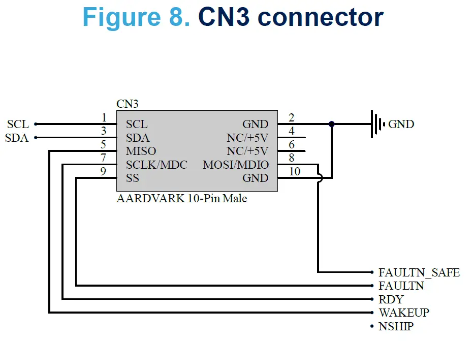
This is a 10-pin IDC style connector, which allows to either connect an Aardvark I2C/SPI Host Adapter or a Beagle I2C/SPI Protocol Analyzer to the L9961 demo board.
Jumpers and connectors
L9961 demo board jumpers and connectors
Table 1. L9961 demo board jumpers and connectors description
| Name | Description | Configuration | Type |
| CN1 | Remote sense: used to route sense signals from the 5-cell battery board to the L9961 demo board | – | 10-pin IDC style |
| CN2 | Battery pack: used to route the power signals from the 5-cell battery board to the L9961 demo board | – | 4-pin Phoenix header |
| CN3 | Total phase: used to connect an Aardvark I2C/SPI Host Adapter or a Beagle I2C/SPI Protocol Analyzer | – | 10-pin IDC style |
| CN7, CN10 | ST morpho connector: used to place L9961 demo board on top of the NUCLEO-G071RB micro board | – | – |
| J1 | Used to measure current flowing into VB pin | – | – |
| J2 | VIO voltage selector | 1-2: 3.3 V from micro 2-3: 3.3 V from L9961 (VREG) | – |
|
J4 |
Used to select micro power source | OPEN: micro is fed from the NUCLEO- G071RB micro board USB CLOSE: micro is fed from VREG. Note: If μC is fed from VREG, JP3 jumper must be open on the NUCLEO-G071RB micro board |
– |
|
J5 |
Battery simulator: used to simulate battery pack | OPEN: battery simulator circuit is disconnected. Note: This configuration is used when the 5-cell battery board is connected CLOSED: battery simulator circuit is connected |
Multiple position jumper |
| J6A | Used to connect NSHIP pin to B+ | – | – |
| J6B | Used to drive NSHIP pin from micro | – | – |
| J6C | Used to drive WAKEUP pin from SW1 push button | – | – |
| J13, J14 | Used to bypass the HS relay MOSFETs | OPEN: when HS relay MOSFETs is used CLOSED: when LS relay MOSFETs is used | Soldered jumper |
| J19, J20 | Used to bypass the LS relay MOSFETs | OPEN: when LS relay MOSFETs is used CLOSED: when HS relay MOSFETs is used | Soldered jumper |
| J15, J16, J17, J18 | Used to configure the relay MOSFETs to either high or low-side usage | 1-2: HS configuration is selected 2-3: LS configuration is used | – |
|
SW1 | Push button: used to take the device out of SHIPMENT state Note: If J6C jumper is closed, the SW1 is also used to take the device out of STADNBY state. |
– |
– |
NUCLEO-G071RB micro board jumpers and connectors
Table 2. NUCLEO-G071RB micro board jumpers and connectors description
| Name | Description | Configuration | Type |
| CN2 | STLINK USB connector | – | USB micro-B |
| CN7, CN10 | ST morpho connector: used to pace L9961 demo board on top of the NUCLEO-G071RB micro board | – | – |
|
JP2 |
5 V jumper selection(1) | OPEN: no 5 V power 1-2 CLOSED: 5 V from STLINK 3-4 CLOSED: 5 V from VIN 7 V to 12 V 5-6 CLOSED: 5 V from E5V 7-8 CLOSED: 5 V from USB_CHG |
– |
| JP3 | STM32 VDD current measurement | Opened when micro is powered from VREG | – |
1. See UM2324 for further details.
5-cell battery board connectors
Table 3. 5-cell battery board connectors description
| Name | Description | Configuration | Type |
| CN1 | Remote sense: used to route sense signals from the 5-cell battery board to the L9961 demo board | – | 10-pin IDC style |
| CN2 | Battery pack: used to route the power signals from the 5-cell battery board to the L9961 demo board | – | 4-pin Phoenix header |
| CN3 | Charge/Discharge: used to connect a load or charger to the battery pack | – | 2-pin Phoenix header |
Application setup
System requirements
To set up the demo and run the application with the evaluation kit, the following items are required:
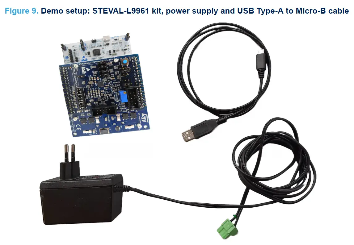
- STEVAL-L99615C kit
- USB Type-A to Micro-B cable
- a portable power supply (up to 20 V, 1 A) to feed the STEVAL-L99615C kit (in case a real battery is not available), possibly equipped with a two or four position plug 7.62MM connector as the Wurth 691351400002 or 691351400004, like the one shown in Figure 9.
- the evaluation GUI contained in the STSW-L99615C
- a laptop to install the evaluation GUI contained in the STSW-L99615C
How to run the application demo
To run the application demo, in voltage and NTC temperature acquisition mode, follow the procedure below: Step 1. Verify that the setting of the STEVAL-L99615C jumpers respects the configuration reported in Table 4.
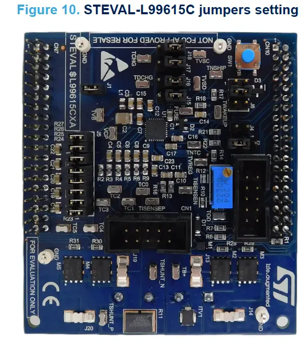
Table 4. Jumper settings
| Name | Board | Description | Configuration |
| J1 | EXP. BOARD | Used to measure current flowing into VB pin | Closed |
| J2 | EXP. BOARD | VIO voltage selector | 2-3: 3.3 V from L9961 (VREG) |
| J4 | EXP. BOARD | Used to select micro power source | Closed |
|
J5 |
EXP. BOARD | Battery simulator – used to simulate battery pack | Closed Note: It is assumed that 5- cell battery board is not used. |
| J6B | EXP. BOARD | Used to drive NSHIP pin from micro | Closed |
| J15, J16, J17, J18 | EXP. BOARD | Used to configure the relay MOSFETs to either high or low-side usage | 1-2: HS configuration is selected |
| J13, J14 | EXP. BOARD | Used to bypass the HS relay MOSFETs | Closed |
| J19, J20 | EXP. BOARD | Used to bypass the LS relay MOSFETs. | Closed |
| JP3 | NUCLEO | STM32 VDD current measurement | Open |
| JP2 | NUCLEO | STM32 5 V jumper selection | 1-2: 5 V from STLINK |
| CN4 | NUCLEO | STM32 SWD interface | Closed |
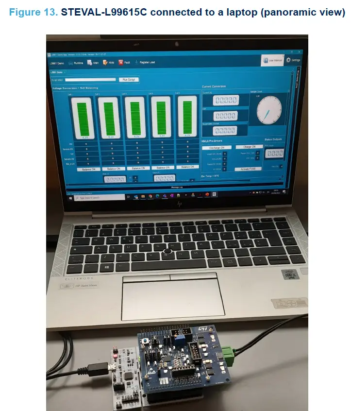
Step 2. After installing the GUI from the STSW-L99615C SW package to the laptop, and confirming that the kit Nucleo board is programmed with the firmware binary contained in the same SW package (refer to the UM3141), connect the STEVAL-L99615C to the laptop through the USB cable.
Note: In the case of NUCLEO programming, refer to the STM32CubeProgrammer user manual for firmware uploading.
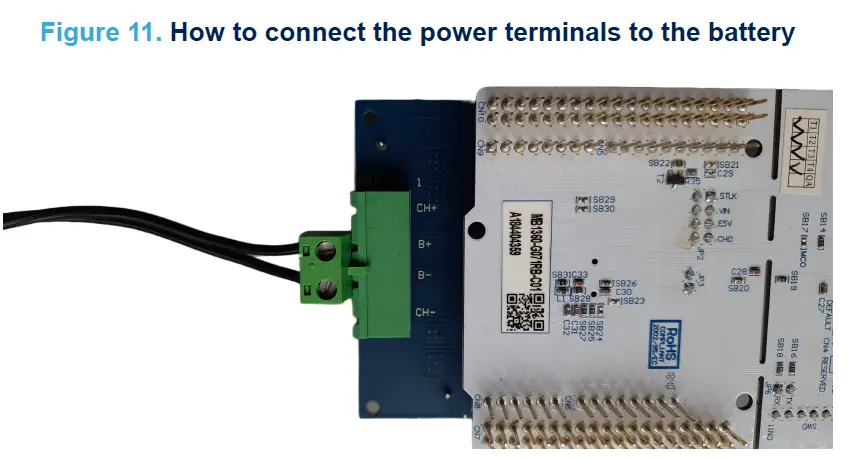
Step 3. Connect the power supply terminals to the B+ and B- pins of the battery pack connector (CN2), and power on the appliance (suggested setting 7.5 V, 1 A as test rating).
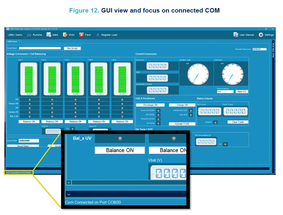
Step 4. Launch the GUI on the laptop and verify the COM used by the evaluation board is recognized by laptop Operative System (WINDOWS in the described case) device manager. If recognized, the GUI releases a message on the left part of the bottom side of its template, referring to the connected COM number used.
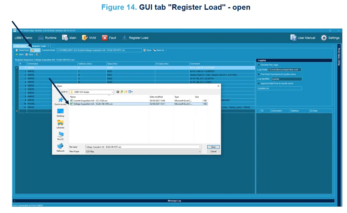
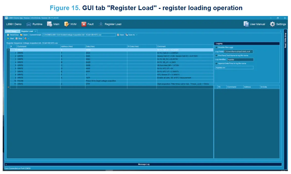
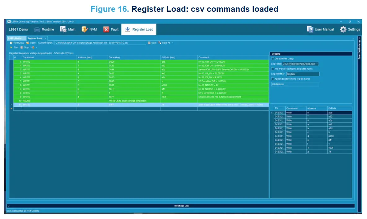
Step 5. Clicking on the GUI tab “Register Load”, upload the example CSV file “Voltage Acquistion Init – 5Cell+VB+NTC.csv” also embedded in the SW package file, and then click the “Play” button. This operation presets an instruction set that permits the GUI to demonstrate the acquisitions of voltage cells and battery pack, and also NTC acquisition. After completing the register loading operation, press OK to begin voltage acquisition.
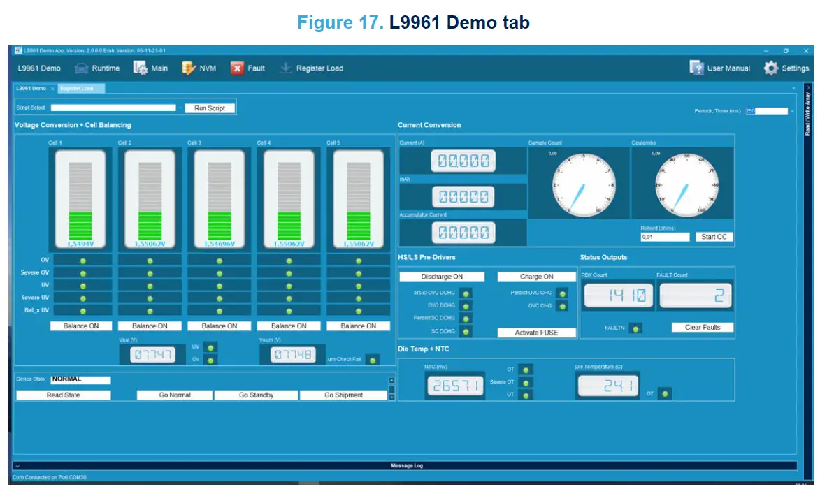
Step 6. Then, opening the “L9961 Demo” tab and setting the Periodic Timer (for example to 250 ms), it is possible to observe the direct acquisition of the voltages on each cell: in fact, applying 7.5 V to the CN2 connector (on VB+ and VB+ pins), the five resistive dividers integrated in the STEVAL-L99615C expansion board and emulating the battery pack circuit, return 1.5 V for each cell.
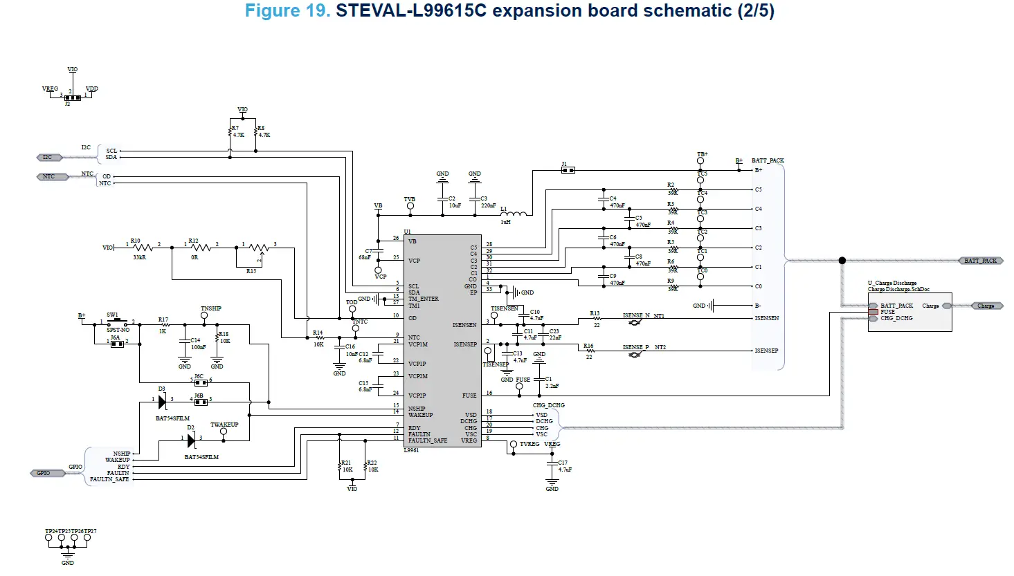
Board schematics
Note: The schematic diagrams below refer to the expansion board included in the STEVAL-L99615C evaluation kit. For the schematic diagrams of the NUCLEO-G071RB development board, see the related web page.
Figure 18. STEVAL-L99615C expansion board schematic (1/5)
Bill of materials
Note: The BOM below refers to the expansion board included in the STEVAL-L99615C evaluation kit. For the BOM of the NUCLEO-G071RB development board, see the related web page.
Table 5. Expansion board bill of materials
| Item | Quantity | Reference | Value | Description | Manufacturer | Order code |
| 1 | 2 | D2, D3 | BAT54FILM, SOT23 | Small signal Schottky diode | STMicroelectronics | BAT54FILM |
| 2 | 1 | C1 | 2.2nF | CAP CER 2.2UF 50V X7R 0805 | KEMET | C0805C222K5RAC7800 |
| 3 | 1 | C2 | 10uF | CAP CER 10UF 50V X7R 1210 | KEMET | C1210C106K5RAC7800 |
| 4 | 1 | C3 | 220nF | CAP CER SMD 0805 2.2UF 10% X7R 5 | KEMET | C0805C224K5RAC7025 |
| 5 | 1 | C7 | 68nF | CAP CER 0.068UF 50V X7R 0805 | KEMET | C0805C683K5RAC7800 |
| 6 | 1 | C14 | 100nF | CAP CER 0.1UF 50V X7R 0805 | KEMET | C0805C104K5RAC7800 |
| 7 | 1 | C16 | 10nF | CAP CER 10000PF 50V X7R 0805 | KEMET | C0805C103K5RAC7210 |
| 8 | 1 | C23 | 22nF | CAP CER 0.022UF 50V X7R 0805 | KEMET | C0805C223K5RAC7800 |
| 9 | 2 | C12, C15 | 6.8nF | CAP CER 6800PF 50V X7R 0805 | KEMET | C0805C682K5RAC7800 |
| 10 | 4 | C10, C11, C13, C17 | 4.7uF | CAP CER 4.7UF 25V X7R 0805 | KEMET | C0805C475M3RAC7800 |
| 11 | 10 | C4, C5, C6, C8, C9, C18, C19, C20, C21, C22 | 470nF | CAP CER 0.47UF 50V X7R 0805 | KEMET | C0805C474M5RAC7800 |
| 12 | 2 | CN7, CN10 | ESQ-119-24-T-D | CONN SOCKET 38POS 0.1 TIN PCB | Samtec Inc. | ESQ-119-24-T-D |
| 13 | 1 | J6 | TSW-103-07-F-D | CONN HEADER VERT 6POS 2.54MM | Samtec Inc. | TSW-103-07-F-D |
| 14 | 1 | J5 | TSW-108-07-F-D | CONN HEADER VERT 16POS 2.54MM | Samtec Inc. | TSW-108-07-F-D |
| 15 | 1 | R10 | 33K | RES SMD 33KΩ 5% 1/10W 0603 | Bourns Inc. | CR0603-JW-333ELF |
| 16 | 1 | R12 | 0 | RES SMD 0 Ω JUMPER 1/10W 0603 | Panasonic Electronic Components | ERJ-3GEY0R00V |
| 17 | 1 | R15 | 3296W-1-204LF | TRIMMER 200KΩ 0.5W PC PIN TOP | Bourns Inc. | 3296W-1-204LF |
| 18 | 2 | CN1, CN3 | 30310-6002HB | CONN HEADER VERT 10POS 2.54MM | 3M | 30310-6002HB |
| 19 | 1 | CN2 | 1728879 | TERM BLOCK HDR 4POS 90DEG 7.62MM | Phoenix Contact | 1728879 |
| 20 | 1 | L1 | 1uH | FIXED IND 1UH 300MA 150 MΩ SMD | KEMET | L0805C1R0MPWST |
| 21 | 1 | ITV1 | ITV4030L2015NR | FUSE BATTERY PROTECTOR 20V 15A | Littelfuse Inc. | ITV4030L2015NR |
| Item | Quantity | Reference | Value | Description | Manufacturer | Order code |
| 22 | 4 | J13, J14, J19, J20 | 5102 | MICRO-MINI 6.9MM SMT JMPR | Keystone Electronics | 5102 |
| 23 | 2 | J1, J4 | TSW-102-07-F-S | CONN HEADER VERT 2POS 2.54MM | Samtec Inc. | TSW-102-07-F-S |
| 24 | 5 | J2, J15, J16, J17, J18 | TSW-103-07-G-S | CONN HEADER VERT 3POS 2.54MM | Samtec Inc. | TSW-103-07-G-S |
| 25 | 1 | U1 | L9961, VFQFPN 5X5X1 32L P0.5 | Chip for consumer battery management applications up to 5 cells | STMicroelectronics | |
| 26 | 1 | D1 | MMSZ4701T1G | DIODE ZENER 14V 500MW SOD123 | ON Semiconductor | MMSZ4701T1G |
| 27 | 1 | R1 | 2.2K | RES SMD 2.2KΩ 1% 1/8W 0805 | Panasonic Electronic Components | ERJ-6ENF2201V |
| 28 | 2 | R7, R8 | 4.7K | RES SMD 4.7KΩ 1% 1/8W 0805 | Panasonic Electronic Components | ERJ-6ENF4701V |
| 29 | 2 | R13, R16 | 22 | RES SMD 22 Ω 1% 1/8W 0805 | Panasonic Electronic Components | ERJ-6ENF22R0V |
| 30 | 4 | R14, R18, R21, R22 | 10K | RES SMD 10KΩ 1% 1/8W 0805 | Panasonic Electronic Components | ERJ-6ENF1002V |
| 31 | 4 | R28, R29, R30, R31 | 2M | RES SMD 2MΩ 1% 1/8W 0805 | Panasonic Electronic Components | ERJ-6ENF2004V |
| 32 | 6 | R2, R3, R4, R5, R6, R9 | 39 | RES SMD 39 Ω 5% 1/4W 0603 | RΩ Semiconductor | ESR03EZPJ390 |
| 33 | 6 | R17, R23, R24, R25, R26, R27 | 1K | RES SMD 1KΩ 1% 1/8W 0805 | Panasonic Electronic Components | ERJ-6ENF1001V |
| 34 | 1 | R11 | 10m | RES 0.01 Ω 1% 7W 2818 | Vishay Dale | WSHM2818R0100FEA |
| 35 | 1 | M1 | STL7N6F7, PowerFLAT 2×2 | N-channel 60V, 21mΩ typ., 7A STripFET F7 Power MOSFET | STMicroelectronics | |
| 36 | 4 | M2, M3, M4, M5 | STL210N4F7, PowerFLAT 5×6 | MOSFET (N-Channel) | STMicroelectronics | STL210N4F7 |
| 37 | 1 | SW1 | KSC701J LFS | SWITCH TACTILE SPST-NO 0.05A 32V | C&K | KSC701J LFS |
| 38 | 4 | TP24, TP25, TP26, TP27 | 5007 | PC TEST POINT COMPACT WHITE | Keystone Electronics | 5007 |
|
39 |
23 | FUSE, TB+, TC0, TC1, TC2, TC3, TC4, TC5, TCHG, TDCHG, TISENSEN, TISENSEP, TNSHIP, TNTC, TOD, TSHUNT_N, TSHUNT_P, TVB, TVREG, TVSC, TVSD, |
PC TEST POINT |
KOA Speer Electronics, Inc. |
RCWCTE |
| Item | Quantity | Reference | Value | Description | Manufacturer | Order code |
| TWAKEUP, VCP | ||||||
| 40 | 20 | Jumper | Jumper | RSPRO | 251-8682 | |
| 41 | 1 | PCB not reference | PCB 2 LAYER FR4 TG 130-140C° | PCB 2 LAYER – size 77.64×70.52×1.6mm thickness copper 70 microns |
Kit versions
Table 6. STEVAL-L99615C versions
| Finished good | Schematic diagrams | Bill of materials |
| STEVAL$L99615CA (1) | STEVAL$L99615CA schematic diagrams | STEVAL$L99615CA bill of materials |
- This code identifies the STEVAL-L99615C evaluation kit first version. The kit consists of a STEVAL-L99615CX whose version is identified by the code STEVAL$L99615CXA and a NUCLEO-G071RB whose version is identified by the code NUG071RB$AU2.
Battery holder
The current chapter contains a reference schematic and relative BOM for developing a 5-cell battery holder. This board, once developed, may be connected to the STEVAL-L99615C kit through the 5-cell battery board connector (CN2), permitting to demonstrate the direct acquisition of the electrical characteristics from the single connected batteries.
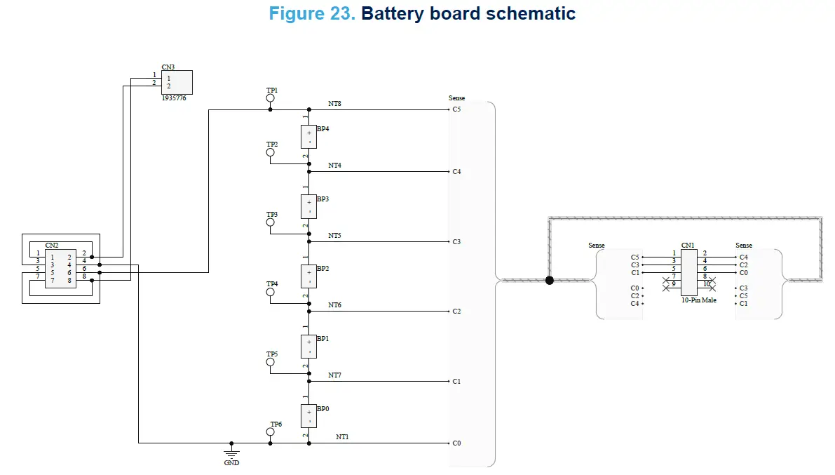
Table 7. Battery holder bill of materials
| Designator | LibRef | Quantity | Manufacturer Name | Manufacturer Part Number | Manufacturer P/N | Manufacturer Part Number | Supplier 1 |
| BP0, BP1, BP2, BP3, BP4 | LI-ION 18650 1 CELL HOLDER | 5 | BH-18650-PC | Digi-Key | |||
| CN1 | CN 2×10 shrouded | 1 | 30310-6002HB | Digi-Key | |||
| CN2 | 1745807 | 1 | 1745807 | Mouser | |||
| CN3 | 1935776 | 1 | Phoenix Contact | 1935776 | |||
| TP1, TP2, TP3, TP4, TP5, TP6 | Test Point | 6 | 5007 | Digi-Key | |||
| flat cable 2×5 compatible with CN1 connector | 1 | ||||||
| Steel Spacer with skrew 2.5mm | 4 |
Regulatory compliance information
Notice for US Federal Communication Commission (FCC)
For evaluation only; not FCC approved for resale.
FCC NOTICE – This kit is designed to allow:
(1) Product developers to evaluate electronic components, circuitry, or software associated with the kit to determine whether to incorporate such items in a finished product and
(2) Software developers to write software applications for use with the end product.
This kit is not a finished product and when assembled may not be resold or otherwise marketed unless all required FCC equipment authorizations are first obtained. Operation is subject to the condition that this product not cause harmful interference to licensed radio stations and that this product accepts harmful interference. Unless the assembled kit is designed to operate under part 15, part 18 or part 95 of this chapter, the operator of the kit must operate under the authority of an FCC license holder or must secure an experimental authorization under part 5 of this chapter 3.1.2.
Notice for Innovation, Science and Economic Development Canada (ISED)
For evaluation purposes only. This kit generates, uses, and can radiate radio frequency energy and has not been tested for compliance with the limits of computing devices pursuant to Industry Canada (IC) rules.
Notice for the European Union
This device is in conformity with the essential requirements of the Directive 2014/30/EU (EMC) and of the Directive 2015/863/EU (RoHS).
Notice for the United Kingdom
This device is in compliance with the UK Electromagnetic Compatibility Regulations 2016 (UK S.I. 2016 No. 1091) and with the Restriction of the Use of Certain Hazardous Substances in Electrical and Electronic Equipment Regulations 2012 (UK S.I. 2012 No. 3032).
Revision history
Table 8. Document revision history
| Revision | Changes | |
| 12-Apr-2023 | 1 | Initial release. |
IMPORTANT NOTICE – READ CAREFULLY
STMicroelectronics NV and its subsidiaries (“ST”) reserve the right to make changes, corrections, enhancements, modifications, and improvements to ST products and/or to this document at any time without notice. Purchasers should obtain the latest relevant information on ST products before placing orders. ST products are sold pursuant to ST’s terms and conditions of sale in place at the time of order acknowledgment.
Purchasers are solely responsible for the choice, selection, and use of ST products and ST assumes no liability for application assistance or the design of purchasers’ products.
No license, express or implied, to any intellectual property right is granted by ST herein.
Resale of ST products with provisions different from the information set forth herein shall void any warranty granted by ST for such product.
ST and the ST logo are trademarks of ST. For additional information about ST trademarks, refer to www.st.com/trademarks. All other product or service names are the property of their respective owners.
Information in this document supersedes and replaces information previously supplied in any prior versions of this document.
© 2023 STMicroelectronics – All rights reserved
References
 STMicroelectronics: Our technology starts with you
-
STEVAL-L99615C - Up to 5 cells BMS for industrial applications based on L9961 - STMicroelectronics
-
STMicroelectronics Trademark List - STMicroelectronics
-
BAT54 - 40 V, 300 mA General purpose Signal Schottky Diode - STMicroelectronics
-
NUCLEO-G071RB - STM32 Nucleo-64 development board with STM32G071RB MCU, supports Arduino and ST morpho connectivity - STMicroelectronics
-
NUCLEO-G071RB - STM32 Nucleo-64 development board with STM32G071RB MCU, supports Arduino and ST morpho connectivity - STMicroelectronics
-
STM32G071RB - Mainstream Arm Cortex-M0+ MCU with 128 Kbytes of Flash memory, 36 Kbytes RAM, 64 MHz CPU, 4x USART, timers, ADC, DAC, comm. I/F, 1.7-3.6V - STMicroelectronics
-
L9961 - Chip for industrial battery management applications up to 5 cells - STMicroelectronics
-
STL210N4F7 - N-channel 40 V, 1.3 m? typ., 120 A STripFET F7 Power MOSFET in a PowerFLAT 5x6 package - STMicroelectronics
-
STL7N6F7 - N-channel 60 V, 21 mOhm typ., 7 A STripFET F7 Power MOSFET in a PowerFLAT 2x2 package - STMicroelectronics
-
L9961 - Chip for industrial battery management applications up to 5 cells - STMicroelectronics
-
STEVAL-L99615C - Up to 5 cells BMS for industrial applications based on L9961 - STMicroelectronics
-
STSW-L99615C - Software GUI for L9961 evaluation board - STMicroelectronics


